EP0929019A1 - System for providing pressure regulation in an enclosure under suction from a vacuum pump - Google Patents
System for providing pressure regulation in an enclosure under suction from a vacuum pump Download PDFInfo
- Publication number
- EP0929019A1 EP0929019A1 EP98403307A EP98403307A EP0929019A1 EP 0929019 A1 EP0929019 A1 EP 0929019A1 EP 98403307 A EP98403307 A EP 98403307A EP 98403307 A EP98403307 A EP 98403307A EP 0929019 A1 EP0929019 A1 EP 0929019A1
- Authority
- EP
- European Patent Office
- Prior art keywords
- vacuum pump
- enclosure
- pump
- pressure
- valve
- Prior art date
- Legal status (The legal status is an assumption and is not a legal conclusion. Google has not performed a legal analysis and makes no representation as to the accuracy of the status listed.)
- Withdrawn
Links
Images
Classifications
-
- F—MECHANICAL ENGINEERING; LIGHTING; HEATING; WEAPONS; BLASTING
- F04—POSITIVE - DISPLACEMENT MACHINES FOR LIQUIDS; PUMPS FOR LIQUIDS OR ELASTIC FLUIDS
- F04D—NON-POSITIVE-DISPLACEMENT PUMPS
- F04D27/00—Control, e.g. regulation, of pumps, pumping installations or pumping systems specially adapted for elastic fluids
-
- G—PHYSICS
- G05—CONTROLLING; REGULATING
- G05D—SYSTEMS FOR CONTROLLING OR REGULATING NON-ELECTRIC VARIABLES
- G05D16/00—Control of fluid pressure
- G05D16/20—Control of fluid pressure characterised by the use of electric means
- G05D16/2006—Control of fluid pressure characterised by the use of electric means with direct action of electric energy on controlling means
- G05D16/2013—Control of fluid pressure characterised by the use of electric means with direct action of electric energy on controlling means using throttling means as controlling means
- G05D16/202—Control of fluid pressure characterised by the use of electric means with direct action of electric energy on controlling means using throttling means as controlling means actuated by an electric motor
-
- F—MECHANICAL ENGINEERING; LIGHTING; HEATING; WEAPONS; BLASTING
- F04—POSITIVE - DISPLACEMENT MACHINES FOR LIQUIDS; PUMPS FOR LIQUIDS OR ELASTIC FLUIDS
- F04B—POSITIVE-DISPLACEMENT MACHINES FOR LIQUIDS; PUMPS
- F04B49/00—Control, e.g. of pump delivery, or pump pressure of, or safety measures for, machines, pumps, or pumping installations, not otherwise provided for, or of interest apart from, groups F04B1/00 - F04B47/00
- F04B49/22—Control, e.g. of pump delivery, or pump pressure of, or safety measures for, machines, pumps, or pumping installations, not otherwise provided for, or of interest apart from, groups F04B1/00 - F04B47/00 by means of valves
- F04B49/24—Bypassing
-
- F—MECHANICAL ENGINEERING; LIGHTING; HEATING; WEAPONS; BLASTING
- F04—POSITIVE - DISPLACEMENT MACHINES FOR LIQUIDS; PUMPS FOR LIQUIDS OR ELASTIC FLUIDS
- F04D—NON-POSITIVE-DISPLACEMENT PUMPS
- F04D27/00—Control, e.g. regulation, of pumps, pumping installations or pumping systems specially adapted for elastic fluids
- F04D27/009—Control, e.g. regulation, of pumps, pumping installations or pumping systems specially adapted for elastic fluids by bleeding, by passing or recycling fluid
-
- F—MECHANICAL ENGINEERING; LIGHTING; HEATING; WEAPONS; BLASTING
- F04—POSITIVE - DISPLACEMENT MACHINES FOR LIQUIDS; PUMPS FOR LIQUIDS OR ELASTIC FLUIDS
- F04B—POSITIVE-DISPLACEMENT MACHINES FOR LIQUIDS; PUMPS
- F04B2205/00—Fluid parameters
- F04B2205/06—Pressure in a (hydraulic) circuit
- F04B2205/064—Pressure in a (hydraulic) circuit in a reservoir linked to the pump inlet
-
- F—MECHANICAL ENGINEERING; LIGHTING; HEATING; WEAPONS; BLASTING
- F04—POSITIVE - DISPLACEMENT MACHINES FOR LIQUIDS; PUMPS FOR LIQUIDS OR ELASTIC FLUIDS
- F04B—POSITIVE-DISPLACEMENT MACHINES FOR LIQUIDS; PUMPS
- F04B2205/00—Fluid parameters
- F04B2205/15—By-passing over the pump
- F04B2205/151—Opening width of a bypass valve
Definitions
- the present invention relates to a system for regulating pressure in an enclosure pumped by a vacuum pump.
- a known method for effecting pressure regulation in a enclosure pumped by a vacuum pump is to use in series, at the suction of the pump, a variable conductance valve for varying the pumped flow and therefore the pressure in the enclosure.
- the degree of opening of the valve is regulated by a control signal from a regulation circuit starting from a set pressure and the pressure measured in the enclosure.
- the object of the present invention is to propose a less expensive system and also less bulky.
- the subject of the invention is therefore a system for ensuring pressure regulation in an enclosure pumped by a vacuum pump, characterized in that a pipe, equipped with a motorized valve with variable opening, connects one or a few stages close to the discharge of the pump to one or a few stages close to its suction, the degree of opening of the valve being controlled by a signal coming from an electronic circuit controlling the pressure P of the enclosure to a value P 1 setpoint, said circuit receiving as input a signal representative of the pressure P measured in the enclosure.
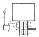
- enclosure 1 This is, for example, a semiconductor processing process chamber. Processing takes place in a very rarefied atmosphere of a treatment gas, the introduction of which is depicted in 2.
- enclosure 1 is pumped by a vacuum pump 3.
- a turbomolecular secondary pump has been shown here comprising a series of finned stages 4. Its outlet 5 is connected to a primary pump not represented.
- a primary pump not represented.
- a pipe 7, equipped with a motorized valve with variable opening 6 connects one or a few stages 8 close to the discharge to one or several stages 9 close to the aspiration.
- This variable opening valve ensures a recirculation making it possible to vary the flow of recirculated gas in the pump and therefore to vary the quantity of gas directly pumped into the process 1.
- the degree of opening of the valve 6 is controlled by a signal 10 at the output of an electronic circuit 11 comprising a pressure control circuit P prevailing in the enclosure to a reference value P 1 which is displayed. .
- the control circuit is conventional and not shown. At the input, it receives a signal 12 from a pressure gauge 13 measuring the pressure P of the enclosure 1.
- the electronic circuit 11 also includes the circuits necessary for control of motor 14 of pump 3.
- Q t Q r + Q p . If Q r is varied by modifying the opening of the valve 6, the flow Q p also varies since the speed of the pump is fixed and therefore its total flow Q t .
- the system according to the invention is particularly advantageous compared to the cited prior art, since instead of having a large diameter valve at the suction of the pump modulating the total flow therefore an expensive and bulky valve, there is only one small valve which lets through only the recirculating flow Q r which is small compared to the total flow. The valve is therefore much smaller and much cheaper.
- the price is roughly divided by 10.
Abstract
Description
La présente invention concerne un système pour assurer une régulation de pression dans une enceinte pompée par une pompe à vide.The present invention relates to a system for regulating pressure in an enclosure pumped by a vacuum pump.
Dans les procédés industriels de fabrication ou de traitement de produits dans des enceintes alimentées en gaz de traitement à des très basses pressions, il est nécessaire de régler la pression de l'enceinte.In industrial processes for manufacturing or processing products in chambers supplied with treatment gas at very low pressures, it is necessary to adjust the chamber pressure.
C'est le cas, par exemple, dans les procédés de fabrication et de traitement des semiconducteurs.This is the case, for example, in the manufacturing and processing processes semiconductors.
Un procédé connu pour effectuer la régulation de pression dans une enceinte pompée par une pompe à vide est d'utiliser en série, à l'aspiration de la pompe, une vanne à conductance variable permettant de faire varier le flux pompé et donc la pression dans l'enceinte. Le degré d'ouverture de la vanne est réglé par un signal de commande provenant d'un circuit de régulation en partant d'une pression de consigne et de la pression mesurée dans l'enceinte.A known method for effecting pressure regulation in a enclosure pumped by a vacuum pump is to use in series, at the suction of the pump, a variable conductance valve for varying the pumped flow and therefore the pressure in the enclosure. The degree of opening of the valve is regulated by a control signal from a regulation circuit starting from a set pressure and the pressure measured in the enclosure.
Cette façon de procéder est onéreuse et encombrante.This procedure is expensive and cumbersome.
La présente invention a pour but de proposer un système moins coûteux et également moins encombrant.The object of the present invention is to propose a less expensive system and also less bulky.
L'invention a ainsi pour objet un système pour assurer une régulation de pression dans une enceinte pompée par une pompe à vide, caractérisé en ce qu'une conduite, équipée d'une vanne motorisée à ouverture variable, relie un ou quelques étages proches du refoulement de la pompe à un ou quelques étages proches de son aspiration, le degré d'ouverture de la vanne étant commandé par un signal en provenance d'un circuit électronique d'asservissement de la pression P de l'enceinte à une valeur P1 de consigne, ledit circuit recevant en entrée un signal représentatif de la pression P mesurée dans l'enceinte.The subject of the invention is therefore a system for ensuring pressure regulation in an enclosure pumped by a vacuum pump, characterized in that a pipe, equipped with a motorized valve with variable opening, connects one or a few stages close to the discharge of the pump to one or a few stages close to its suction, the degree of opening of the valve being controlled by a signal coming from an electronic circuit controlling the pressure P of the enclosure to a value P 1 setpoint, said circuit receiving as input a signal representative of the pressure P measured in the enclosure.
On va maintenant donner la description d'un exemple de mise en oeuvre de l'invention en se référant au dessin annexé comprenant une figure unique.We will now give the description of an example of implementation of the invention with reference to the accompanying drawing comprising a single figure.
En se référant à la figure, on voit une enceinte 1. Il s'agit, par exemple,
d'une chambre de procédé de traitement d'un semiconducteur. Le traitement a lieu
en atmosphère très raréfiée d'un gaz de traitement dont l'introduction est figurée en
2.Referring to the figure, we see an
Pour maintenir la basse pression exigée, l'enceinte 1 est pompée par une
pompe à vide 3.To maintain the required low pressure,
On a figuré ici une pompe secondaire turbomoléculaire comportant une série d'étages à ailettes 4. Son refoulement 5 est relié à une pompe primaire non représentée. On pourrait également utiliser un autre type de pompe telle qu'une pompe Holweck, une pompe hybride ou encore une pompe primaire multi-étagée par exemple une roots multi-étagée.A turbomolecular secondary pump has been shown here comprising a series of finned stages 4. Its outlet 5 is connected to a primary pump not represented. We could also use another type of pump such as a Holweck pump, a hybrid pump or even a multi-stage primary pump for example a multi-level roots.
Selon l'invention, une conduite 7, équipée d'une vanne motorisée à
ouverture variable 6, relie un ou quelques étages 8 proches du refoulement à un ou
plusieurs étages 9 proches de l'aspiration. Cette vanne à ouverture variable assure
une recirculation permettant de faire varier le flux de gaz recirculé dans la pompe et
donc de faire varier la quantité de gaz directement pompé dans la chambre de
procédé 1.According to the invention, a pipe 7, equipped with a motorized valve with
Le degré d'ouverture de la vanne 6 est commandé par un signal 10 en sortie
d'un circuit électronique 11 comprenant un circuit d'asservissement de la pression P
régnant dans l'enceinte à une valeur de consigne P1 que l'on affiche. Le circuit
d'asservissement est classique et non représenté. En entrée, il reçoit un signal 12
provenant d'une jauge de pression 13 mesurant la pression P de l'enceinte 1.The degree of opening of the
Le circuit électronique 11 comprend également les circuits nécessaires au
pilotage du moteur 14 de la pompe 3.The
Ainsi, si Qt désigne le flux total admissible dans la pompe, Qr le flux de gaz
recirculé par la conduite 5 et Qp le flux provenant directement de l'enceinte 1, on
a :
Ainsi, le système selon l'invention est particulièrement avantageux par rapport à l'art antérieur cité, puisqu'au lieu d'avoir une vanne de gros diamètre à l'aspiration de la pompe modulant le flux total donc une vanne onéreuse et encombrante, on n'a plus qu'une petite vanne qui ne laisse passer que le flux Qr de recirculation qui est petit par rapport au flux total. La vanne est donc beaucoup plus petite et beaucoup moins chère. Le prix est grosso modo divisé par 10.Thus, the system according to the invention is particularly advantageous compared to the cited prior art, since instead of having a large diameter valve at the suction of the pump modulating the total flow therefore an expensive and bulky valve, there is only one small valve which lets through only the recirculating flow Q r which is small compared to the total flow. The valve is therefore much smaller and much cheaper. The price is roughly divided by 10.
Claims (1)
Applications Claiming Priority (2)
| Application Number | Priority Date | Filing Date | Title |
|---|---|---|---|
| FR9800036 | 1998-01-06 | ||
| FR9800036A FR2773403B1 (en) | 1998-01-06 | 1998-01-06 | SYSTEM FOR PROVIDING PRESSURE REGULATION IN A VACUUM PUMP ENCLOSURE |
Publications (1)
| Publication Number | Publication Date |
|---|---|
| EP0929019A1 true EP0929019A1 (en) | 1999-07-14 |
Family
ID=9521533
Family Applications (1)
| Application Number | Title | Priority Date | Filing Date |
|---|---|---|---|
| EP98403307A Withdrawn EP0929019A1 (en) | 1998-01-06 | 1998-12-28 | System for providing pressure regulation in an enclosure under suction from a vacuum pump |
Country Status (4)
| Country | Link |
|---|---|
| EP (1) | EP0929019A1 (en) |
| JP (1) | JPH11257278A (en) |
| KR (1) | KR19990067758A (en) |
| FR (1) | FR2773403B1 (en) |
Families Citing this family (1)
| Publication number | Priority date | Publication date | Assignee | Title |
|---|---|---|---|---|
| JP5486184B2 (en) * | 2008-12-10 | 2014-05-07 | エドワーズ株式会社 | Vacuum pump |
Citations (3)
| Publication number | Priority date | Publication date | Assignee | Title |
|---|---|---|---|---|
| FR1470495A (en) * | 1965-03-18 | 1967-02-24 | Oemv Ag | Process and apparatus for the use or exploitation of combustible waste gases from refineries or other installations |
| US4203701A (en) * | 1978-08-22 | 1980-05-20 | Simmonds Precision Products, Inc. | Surge control for centrifugal compressors |
| EP0024823A1 (en) * | 1979-08-22 | 1981-03-11 | Imperial Chemical Industries Plc | Compressor surge control method and apparatus |
-
1998
- 1998-01-06 FR FR9800036A patent/FR2773403B1/en not_active Expired - Fee Related
- 1998-12-28 EP EP98403307A patent/EP0929019A1/en not_active Withdrawn
-
1999
- 1999-01-05 JP JP11000751A patent/JPH11257278A/en active Pending
- 1999-01-06 KR KR1019990000135A patent/KR19990067758A/en not_active Application Discontinuation
Patent Citations (3)
| Publication number | Priority date | Publication date | Assignee | Title |
|---|---|---|---|---|
| FR1470495A (en) * | 1965-03-18 | 1967-02-24 | Oemv Ag | Process and apparatus for the use or exploitation of combustible waste gases from refineries or other installations |
| US4203701A (en) * | 1978-08-22 | 1980-05-20 | Simmonds Precision Products, Inc. | Surge control for centrifugal compressors |
| EP0024823A1 (en) * | 1979-08-22 | 1981-03-11 | Imperial Chemical Industries Plc | Compressor surge control method and apparatus |
Also Published As
| Publication number | Publication date |
|---|---|
| JPH11257278A (en) | 1999-09-21 |
| FR2773403A1 (en) | 1999-07-09 |
| FR2773403B1 (en) | 2000-02-04 |
| KR19990067758A (en) | 1999-08-25 |
Similar Documents
| Publication | Publication Date | Title |
|---|---|---|
| EP1043645B1 (en) | Pressure control system for a vacuum chamber, vacuum pumping unit provided with such a system | |
| US7793685B2 (en) | Controlling gas partial pressures for process optimization | |
| US7253107B2 (en) | Pressure control system | |
| US6328803B2 (en) | Method and apparatus for controlling rate of pressure change in a vacuum process chamber | |
| TW533504B (en) | Gas recirculation flow control method and apparatus for use in vacuum system | |
| WO2001082019A1 (en) | Method and device for conditioning atmosphere in a process chamber | |
| EP0016909A1 (en) | Method of growing plasma oxide on semiconductor substrates and device for carrying out this method | |
| EP0479633B1 (en) | Method and apparatus for supplying gas to an analyser with a very high sensitivity | |
| TW201402950A (en) | Vacuum pump apparatus | |
| FR2835283A1 (en) | METHOD AND APPARATUS FOR REGULATING THE SUPPLY PRESSURE OF AN EXHAUST GAS TURBOCHARGER | |
| FR2645344A1 (en) | DEVICE FOR THE VACUUM DEPOSITION OF FILMS ON SUPPORTS | |
| EP0929019A1 (en) | System for providing pressure regulation in an enclosure under suction from a vacuum pump | |
| JP4555824B2 (en) | Leak detector | |
| KR20210102478A (en) | Vacuum-generating pumping system and pumping method using this pumping system | |
| EP0515255A1 (en) | Process and device for the aspiration f fumes or gases from a metallurgical vessel and device therefor | |
| JP3494457B2 (en) | Vacuum pump device | |
| EP0767307A1 (en) | Secondary pumping group | |
| EP0716296B1 (en) | Leak detector | |
| JP2760331B2 (en) | Vacuum exhaust device | |
| JP4095733B2 (en) | Vacuum pressure control system | |
| FR2792083A1 (en) | Pressure regulation in semi-conductor fabrication chamber under vacuum and associated vacuum pump | |
| JPS6269509A (en) | Low pressure cvd equipment | |
| FR2544522A1 (en) | PRESSURE REPORT SENSOR | |
| JPH01239751A (en) | Exhaust system in vacuum device | |
| JPH06102153A (en) | Method and device for sampling gas from pressure fluctuating vessel |
Legal Events
| Date | Code | Title | Description |
|---|---|---|---|
| PUAI | Public reference made under article 153(3) epc to a published international application that has entered the european phase |
Free format text: ORIGINAL CODE: 0009012 |
|
| AK | Designated contracting states |
Kind code of ref document: A1 Designated state(s): CH DE GB IT LI |
|
| AX | Request for extension of the european patent |
Free format text: AL;LT;LV;MK;RO;SI |
|
| 17P | Request for examination filed |
Effective date: 20000114 |
|
| AKX | Designation fees paid |
Free format text: CH DE GB IT LI |
|
| 17Q | First examination report despatched |
Effective date: 20021128 |
|
| STAA | Information on the status of an ep patent application or granted ep patent |
Free format text: STATUS: THE APPLICATION IS DEEMED TO BE WITHDRAWN |
|
| 18D | Application deemed to be withdrawn |
Effective date: 20030409 |