EP0928882B1 - Steam cooling apparatus for gas turbine - Google Patents
Steam cooling apparatus for gas turbine Download PDFInfo
- Publication number
- EP0928882B1 EP0928882B1 EP98929653A EP98929653A EP0928882B1 EP 0928882 B1 EP0928882 B1 EP 0928882B1 EP 98929653 A EP98929653 A EP 98929653A EP 98929653 A EP98929653 A EP 98929653A EP 0928882 B1 EP0928882 B1 EP 0928882B1
- Authority
- EP
- European Patent Office
- Prior art keywords
- steam
- temperature
- combustor
- flow path
- gas turbine
- Prior art date
- Legal status (The legal status is an assumption and is not a legal conclusion. Google has not performed a legal analysis and makes no representation as to the accuracy of the status listed.)
- Expired - Lifetime
Links
- 238000001816 cooling Methods 0.000 title claims description 89
- 239000007789 gas Substances 0.000 claims description 75
- 230000001105 regulatory effect Effects 0.000 claims description 21
- 239000000567 combustion gas Substances 0.000 claims description 6
- 230000007423 decrease Effects 0.000 claims description 4
- 238000011084 recovery Methods 0.000 description 9
- 238000010586 diagram Methods 0.000 description 8
- 230000008859 change Effects 0.000 description 6
- 230000033228 biological regulation Effects 0.000 description 3
- 238000010792 warming Methods 0.000 description 3
- 238000004891 communication Methods 0.000 description 2
- 230000001934 delay Effects 0.000 description 2
- 238000000034 method Methods 0.000 description 2
- 230000008569 process Effects 0.000 description 2
- 230000007704 transition Effects 0.000 description 2
- 238000010795 Steam Flooding Methods 0.000 description 1
- 230000001276 controlling effect Effects 0.000 description 1
- 238000010438 heat treatment Methods 0.000 description 1
- 238000013021 overheating Methods 0.000 description 1
- 238000010248 power generation Methods 0.000 description 1
- 230000004044 response Effects 0.000 description 1
Images


Classifications
-
- F—MECHANICAL ENGINEERING; LIGHTING; HEATING; WEAPONS; BLASTING
- F01—MACHINES OR ENGINES IN GENERAL; ENGINE PLANTS IN GENERAL; STEAM ENGINES
- F01K—STEAM ENGINE PLANTS; STEAM ACCUMULATORS; ENGINE PLANTS NOT OTHERWISE PROVIDED FOR; ENGINES USING SPECIAL WORKING FLUIDS OR CYCLES
- F01K23/00—Plants characterised by more than one engine delivering power external to the plant, the engines being driven by different fluids
- F01K23/02—Plants characterised by more than one engine delivering power external to the plant, the engines being driven by different fluids the engine cycles being thermally coupled
- F01K23/06—Plants characterised by more than one engine delivering power external to the plant, the engines being driven by different fluids the engine cycles being thermally coupled combustion heat from one cycle heating the fluid in another cycle
- F01K23/10—Plants characterised by more than one engine delivering power external to the plant, the engines being driven by different fluids the engine cycles being thermally coupled combustion heat from one cycle heating the fluid in another cycle with exhaust fluid of one cycle heating the fluid in another cycle
- F01K23/101—Regulating means specially adapted therefor
Definitions
- the present invention relates to a device for steam cooling the combustor of a gas turbine which, in a combined plant in which a gas turbine and a steam turbine are combined, is capable of accurately controlling the temperature of the steam at planned temperatures even during periods of load change.
- FIG. 7 is a schematic diagram of a plant having a gas turbine combustor which is subjected to steam cooling, in a combined plant in which a gas turbine and a steam turbine are combined.
- a combustion gas 7, which is created as a result of power generation in gas turbine 1 and is discharged is supplied to the boiler 4, and in boiler 4, steam 9 is generated by this high-temperature combustion gas 7 from the gas turbine 1, and the exhaust gas 50 is discharged to the atmosphere from smokestack 51.
- the steam 9, which is generated in the boiler 4 is supplied to steam turbine 5, and this turns a power generator, so that electric power is obtained.
- the cooling of the combustor of gas turbine 1 is conducted by extracting a portion of the steam produced by boiler 4 and conveying this steam 40 to the combustor, and the steam heated during this cooling process as recovered steam 41 is then reused by being returned to steam turbine 5.
- FIG. 6 is a schematic flow diagram of a steam-cooling system for gas turbine combustors in a conventional combined plant.
- controller 2 controls the flow of the steam, while combustion gas from the gas turbine 1 is led to the boiler 4, which generates steam.
- this steam-cooling system is provided with an auxiliary steam source 3, a steam turbine 5, and a condenser 6.
- Steam recovery valve 11 is provided in the recovered steam flow path 61 from the outlet of the combustor of gas turbine 1.
- steam valve 12 is provided in extracted steam flow path 62 from the boiler 4 to the inlet of the combustor of gas turbine 1.
- Auxiliary steam valve 13 is provided in flow path 63 in order to introduce the steam from the auxiliary steam source 3 into the flow path 62 leading to the inlet of the combustor of gas turbine 1.
- the opening and closing of these valves 11 through 13 is controlled by the controller 2.
- a temperature sensor 21 which detects the temperature of the steam flowing through the auxiliary steam flow path 63
- a temperature sensor 22 which detects the temperature of the steam flowing into the inlet of the combustor of gas turbine 1
- a temperature sensor 31 which measures the temperature of the steam at the outlet of the combustor of gas turbine 1
- controller 2 the detected values detected by these temperature sensors are input into controller 2.
- an actual plant would be provided with a drain exhaust system, opening and closing valves, flow rate and pressure adjustment valves, pressure detectors, and the like; however, as these are not required for an explanation of the technological background of the present invention, an explanation thereof will be omitted here.
- auxiliary steam valve 13 Prior to starting, the auxiliary steam valve 13 is first opened, and auxiliary steam is allowed to flow into the auxiliary steam flow path 63 from auxiliary steam source 3, and this flows through the combustor of gas turbine 1 via flow path 62, and is discharged via a flush pipe which is not depicted in the figure, so that a warming up is conducted.
- gas turbine 1 is started, and after a predetermined period of time, the auxiliary steam valve 13 is closed, while steam valve 12 and steam recovery valve 11 are opened, the steam extracted from the boiler 4 is supplied to the combustor of gas turbine 1, and the combustor is cooled using this steam, while the steam heated in the process of cooling is returned to steam turbine 5 and reused.
- the amount of cooling steam supplied to the combustor of gas turbine 1 is adjusted to the amount necessary for the gas turbine load by conducting programmed control in the controller 2.
- the opening and closing of the auxiliary steam valve 13, the steam valve 12, and the steam recovery valve 11 is conducted in accordance with a program predetermined, and steam cooling is conducted so that the combustor of gas turbine 1 remains at planned temperatures from the starting of the gas turbine and throughout the operation thereof.
- the combustor is cooled using steam extracted from a boiler, and after it has been used for cooling, the steam is returned to the steam turbine as recovered steam, and the required amount of steam is controlled by a controller using a program determined in advance in accordance with the load on the gas turbine.
- JP-A- 7 119 413 discloses a steam cooling system according to the first part of claim 1.
- An embodiment thereof comprises a gas turbine 3, a steam turbine 25 and two boilers 500 and 517.
- the present invention has as an object thereof to provide a steam-cooling system for gas turbine combustors which, in combined plants having a steam-cooled combustor, is capable of maintaining the temperature of steam directed from the combustor to a steam turbine at predetermined temperatures even during the starting of plant or during periods of load change.
- the invention of the present application comprises a steam-cooling system for gas turbine combustors in combined plants, in which combustion gas exhausted from a gas turbine is directed to a boiler, steam is generated in this boiler and a steam turbine is operated using this steam while a portion of the steam from the boiler is extracted and supplied to the combustor of the gas turbine to cool the combustor, and after being used for this cooling, the steam is returned to the steam turbine; which comprises: a temperature sensor for detecting the temperature of steam in a cooling steam outlet side flow path of the gas turbine combustor; a steam flow path through which steam is extracted from the exhaust system of the steam turbine and the extracted steam from the exhaust system of the steam turbine is let into the cooling steam outlet side flow path of the gas turbine combustor via a temperature regulating valve; and a controller which receives detected temperature signals from the temperature sensor and conducts control such that the valve is opened when the detected temperature is in excess of a predetermined value, and closed the valve when this temperature is equal to or lower than the predetermined value.
- the controller conducts control such that when the temperature of the steam at the cooling steam outlet side of the gas turbine combustor exceeds a planned temperature set in advance, the temperature regulating valve opens.
- the controller which receives this detected temperature signal controls opening operation of the valve, and this allows low-temperature steam extracted from the exhaust system of the steam turbine to enter into the cooling steam output side flow path of the gas turbine combustor, thus regulating temperature in such a way as to decrease the temperature of the steam flowing in the cooling steam outlet side flow path.
- the valve is closed, and normal control resumes.
- a steam-cooling system for gas turbine combustors comprising a pressure sensor for detecting a difference in pressure between the inlet side flow path and the outlet side flow path of the cooling steam of the combustor, and a bypass flow path for allowing an outflow of steam from the cooling steam outlet side flow path of the combustor to the condenser via a bypass valve; a detected temperature signal from the temperature sensor and a pressure signal from the pressure sensor are input into the controller, and the controller conducts control such that when the detected temperature is higher than a predetermined value, the temperature regulating valve is opened, while when this temperature is equal to or lower than the predetermined value, the valve is closed, and furthermore conducts control such that when the pressure is lower than a predetermined value, the bypass valve is opened, while when the predetermined value is reached, the bypass valve is closed.
- the controller controls opening operation of the bypass valve, the cooling steam outlet side flow path of the combustor is placed in communication with the condenser, and the pressure difference between the cooling steam inlet side flow path and outlet side flow path of the combustor is forcibly increased, so that steam is caused to flow, and thus it is possible to prevent an excessive increase in the temperature of the steam flowing through the cooling steam outlet side flow path of the gas turbine combustor even during the starting of plant or during periods of load fluctuation, and thus to conduct control at planned values.
- Another mode of the invention of the present application comprises a steam-cooling system for gas turbine combustors, wherein, in the state in which the temperature regulating valve is opened, if the temperature detected by the temperature sensor is not reduced to a predetermined value, the controller conducts control so as to open the bypass valve.
- the controller first controls opening operation of the temperature control valve, and in cases in which this control is insufficient, next controls opening operation of the bypass valve. Furthermore, in cases in which the difference in pressure between the cooling steam inlet side flow path and outlet side flow path of the combustor is low, this bypass valve is opened irrespective of the steam temperature in the vicinity of the outlet of the combustor. Accordingly, using both values detected by the pressure sensor and the temperature sensor, the controller controls the bypass valve, so that the reliability of control is improved.
- Figure 1 is a schematic flow diagram of a steam-cooling system for gas turbine combustors in accordance with an embodiment of the present invention.
- references 1, 3 through 6, 11 through 13, and 21 through 22 have functions identical to those in the conventional example shown in Figure 6, and a detailed description thereof will be omitted here, and they simply will be described by reference.
- the characteristic parts of the present invention are those given reference numbers 10, 30, and 31, and these will be described in detail hereinbelow.
- controller 10 conducts control so as to open the auxiliary steam valve 13 prior to the starting, similar to the above-mentioned conventional example, and auxiliary steam flows from auxiliary steam source 3 into auxiliary steam flow path 63, and the steam is led to the combustor of gas turbine 1 via flow path 62, and is discharged via a flush pipe which is not depicted in the figure, so that a warming up is conducted.
- auxiliary steam valve 13 is closed, and steam valve 12 is simultaneously opened, and steam recovery valve 11 is also opened and the extracted steam from boiler 4 is supplied to the combustor of gas turbine 1, the combustor is cooled, and after being used for cooling, the steam is returned to steam turbine 5 via cooling steam outlet side flow path 61.
- the steam from boiler 4 is extracted from the outlet of an IPSH (intermediate pressure super heater), and the recovered steam is returned to an HTR (high-temperature steam reheater).
- Controller 10 controls the amount of steam required for combustor cooling in accordance with the starting of plant or during changes in the load during periods of load fluctuation; however, such control does not immediately reflect the pressures and temperatures of the steam generated in the boiler, but rather a delay is produced, and as a result of this delay, there are cases in which the cooling steam for the combustor is insufficient and the steam temperature at the combustor outlet is in excess of the planned temperature.
- the temperature signal of temperature sensor 31 is input at the controller 10, and when the detected temperature exceeds a planned temperature which is set in advance, the controller 10 conducts control such that the temperature valve 30 is opened.
- the exhaust gas from steam turbine 5, that is to say, low-temperature reheated steam is extracted, and this is injected into the flow path 61 at the recovered steam side, that is to say, the cooling steam outlet side of the combustor.
- the temperature of the steam at the combustor outlet side which had become high, is regulated and the temperature thereof decreases, and when this reaches the planned temperature, control is conducted so that the temperature regulation valve 30 is closed, and the control of normal operations is resumed.
- FIG. 2 is a timing chart of the control in an actual embodiment of the explanation above.
- the uppermost level indicates the patterns of the rotation and load of gas turbine 1; the load of gas turbine 1 increases slowly from a period of 30 minutes after the starting, and at some point after the passage of 150 minutes it reaches 100%.
- the controller 10 in accordance with the load pattern, maintains auxiliary steam valve 13 in an open state prior to the starting of gas turbine 1 and for a period of more than 60 minutes after the starting thereof; the auxiliary steam from auxiliary steam source 3 is let into flow path 62.
- the amount of steam necessary for the combustor after the supply of auxiliary steam is also set in accordance with this load pattern.
- the controller 10 opens steam valve 12 and steam recovery valve 11 simultaneously with the closing of auxiliary steam valve 13; by allowing steam from boiler 4 to enter flow path 62 in accordance with the pattern of the amount of steam required for the combustor, the combustor is cooled. After it is used for cooling, this steam is returned to steam turbine 5 via steam recovery valve 11.
- the recovered steam temperature (combustor outlet temperature) of the temperature sensor 31 experiences a transition at the planned temperature; however, when there is a sudden increase in the load at some point after the passage of 150 minutes, as a result of the delay in the supply of steam and the like, the steam temperature rises above the planned temperature T.
- the controller 10 opens the temperature regulating valve 30, and the exhaust gas from steam turbine 5, that is to say, the low-temperature reheated steam, is extracted, and this is let into the cooling steam outlet side flow path 61 of the combustor and the temperature is regulated, and when the temperature returns to the planned value, the temperature regulating valve 30 is closed, and normal control is resumed.
- a temperature sensor 31 and a temperature regulating valve 30 are provided in order to prevent an excessive increase in the steam temperature at the outlet of the combustor, and control is exerted by the controller 10, and a portion of the exhaust gases of the steam turbine 5 are extracted and returned to the combustor outlet side, so that it is possible to control the temperature at the outlet of the combustor of gas turbine 1 at planned values even during the starting of plant or during periods of load change, and furthermore, in order to respond to insufficiencies in the steam used for combustor cooling, it is not necessary to increase the size of the boiler.
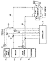
- FIG 3 is a schematic flow diagram of a steam-cooling system for gas turbine combustors in accordance with another embodiment of the present invention; those parts having identical reference numbers as in Figure 1 have the same function.
- a temperature sensor 23 for detecting the steam temperature at the combustor outlet is provided in the vicinity of the combustor outlet in the flow path 61 at the cooling steam outlet side of the combustor, and a bypass valve 14 is placed in the flow path 64 (the bypass path) which leads to the condenser from the vicinity of the outlet of the combustor in flow path 61 at the cooling steam outlet side of the combustor, and the values detected by the temperature sensor 23 are transmitted to the controller 10.
- a pressure sensor 24 for detecting the difference in pressure between the steam inlet side flow path 62 and the steam outlet side flow path 61 of the combustor is installed between flow path 61 and flow path 62, and the value detected thereby is transmitted to controller 10.
- Controller 10 conducts the following control, which is a characteristic feature of the present invention.
- the pressure difference detected by pressure sensor 24 at the combustor outlet of gas turbine 1 is small, the necessary amount of steam is not flowing to the combustor, so that the temperature of temperature sensor 31 also increases, and in such a case, in order to guarantee the necessary amount of steam to the combustor, controller 10 controls opening operation of the bypass valve 14, and control is conducted so that steam flows to condenser 6 via bypass path 64. In this way, it is possible to prevent an excessive heating of the combustor by means of forcing a difference in pressure between the combustor outlet and inlet and causing a flow of steam.
- the temperature regulation valve 30 is first opened, and if control cannot be effected in this way, then the bypass valve 14 is also opened. Furthermore, when the difference in pressure between the cooling steam inlet side flow path 62 and outlet side flow path 61 of the combustor is low, then this bypass valve 14 is opened irrespective of the steam temperature of the cooling steam outlet side flow path 61 of the combustor detected by temperature sensor 31.
- the temperature may be detected using the temperature sensor 23, which is provided in the vicinity of the combustor outlet in the cooling steam outlet side flow path 61 of the combustor, in place of the temperature sensor 31.
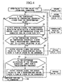
- FIG. 4 is a flow chart showing, among the control conducted by controller 10, the parts which are characteristic of the present invention.
- S1 the cooling of the combustor by steam is conducted, steam valve 12 is opened and steam is led from boiler 4 to the combustor, the combustor is cooled, and the steam is recycled to steam turbine 5 via steam recovery valve 11.
- the temperature in the vicinity of the outlet of the combustor may be detected using the temperature sensor 23 in place of the temperature sensor 31, and a determination may be made in S2 as to whether this temperature is higher than the temperature detected by temperature sensor 31, and the same control may be conducted.
- FIG. 5 is a timing chart of the control in the embodiment of the explanation above.
- the uppermost level shows the pattern of the rotational speed and load of the gas turbine 1; the load of gas turbine 1 exhibits a pattern such that it slowly increases after a period of 30 seconds from starting, and reaches a level of 100% at a point after the passing of 150 minutes.
- Controller 10 in accordance with this load pattern, maintains the auxiliary steam drive 13 in an opened state from before the starting of gas turbine 1 to a point in time after the passage of 60 minutes or more from the starting, and causes an inflow of auxiliary steam from the auxiliary steam source 3 into flow path 62.
- the amount of steam necessary for the combustor after the supply of this auxiliary steam is also set in accordance with the load pattern.
- Controller 10 controls opening operation of steam valve 12 and steam recovery valve 11 simultaneously with the closing of auxiliary steam valve 13, and by means of causing an inflow of steam from boiler 4 into flow path 62 in accordance with the pattern of the necessary amount of steam for the combustor, the combustor is cooled. After being used for cooling, the steam is recycled to steam turbine 5 via steam recovery valve 11.
- the recovered steam temperature (combustor outlet temperature) of temperature sensor 31 experiences a transition at a planned temperature at a point up to 150 minutes after the starting; however, during the rapid increase in the load after 150 minutes of operation, as a result of the delay in the supply of steam and the like, the steam temperature exceeds the planned temperature T.
- controller 10 controls opening operation of temperature regulating valve 30, and the exhaust gas from steam turbine 5, that is to say, the low-temperature reheated steam, is extracted, and this is injected into the cooling steam outlet side flow path 61 of the combustor, and the temperature is regulated, and when the temperature returns to the planned value, the temperature regulating valve 30 is closed, and normal control is resumed.
- the operation is identical to that established in Figures 1 and 2.
- bypass valve 14 is opened irrespective of the steam temperature at the cooling steam outlet side flow path 61 of the combustor detected by temperature sensor 31.
- a temperature sensor 31 and a temperature regulating valve 30 are provided in order to prevent an excessive increase in the steam temperature at the combustor outlet, and by means of controller 10, a portion of the steam discharged from steam turbine 5 is extracted and this is returned to the combustor outlet. Furthermore, in addition to this control, temperature sensor 23, pressure sensor 24, and bypass valve 14 are provided and the steam outputted by the combustor is caused to flow out to condenser 6.
- the cooling steam outlet side flow path of the combustor is placed in communication with the condenser by opening a bypass valve, and the difference in pressure between the cooling steam inlet side flow path and outlet flow path of the combustor is increased, and control is conducted such that steam is caused to flow, so that it is possible to control the steam temperature in the cooling steam outlet side flow path of the combustor of a gas turbine at planned values without an excessive increase therein even during the starting or during periods of load change.
- the controller opens the bypass valve, and thereby, in addition to the value detected by the pressure sensor, control is conducted while detecting the temperature of the cooling steam outlet side flow path of the combustor as well, so that the reliability of control is increased.
Description
Claims (3)
- A steam-cooling system for gas turbine combustors in combined plants which is provided with a gas turbine (1) having the gas turbine combustor for generating combustion gas, a boiler (4) for generating a steam with the combustion gas from the gas turbine (1), a steam turbine (5) driven by the steam from the boiler (4), a cooling steam inlet side flow path (62) of the gas turbine combustor connected to the boiler (4), a cooling steam outlet side flow path (61) of the gas turbine combustor connected to the steam turbine (5), and a temperature sensor (31) for detecting the temperature of the steam flowing through the cooling steam outlet side flow path (61);
characterized in that the steam-cooling system comprises:a steam flow path for directing steam exhausted from the steam turbine (5) to the cooling steam outlet side flow path (61) via a temperature regulating valve (30); anda controller (10) which opens the temperature regulating valve (30) when the temperature detected by the temperature sensor (31) is in excess of a predetermined value, and closes the temperature regulating valve (31) when the temperature is equal to or lower than the predetermined value. - A steam-cooling system for gas turbine combustors in accordance with claim 1, comprisinga pressure sensor (24) for detecting a pressure difference between the cooling steam inlet side flow path (62) and the cooling steam outlet side flow path (61) anda steam bypass flow path (64) connected between the cooling steam outlet side flow path (61) and a condenser (6) via a bypass valve (14); and whereinthe controller (10) opens the bypass valve (14) when the pressure difference is lower than a predetermined value, and closes the bypass valve (14) when the pressure difference reaches the predetermined value.
- A steam-cooling system for gas turbine combustors in accordance with claim 2, wherein the controller (10) opens the bypass valve (14) when the temperature regulating valve (30) is opened and the temperature detected by the temperature sensor (31) does not decrease to a predetermined value.
Applications Claiming Priority (5)
| Application Number | Priority Date | Filing Date | Title |
|---|---|---|---|
| JP16723897 | 1997-06-24 | ||
| JP16723897 | 1997-06-24 | ||
| JP29710497 | 1997-10-29 | ||
| JP29710497 | 1997-10-29 | ||
| PCT/JP1998/002801 WO1998059158A1 (en) | 1997-06-24 | 1998-06-24 | Steam cooling apparatus for gas turbine |
Publications (3)
| Publication Number | Publication Date |
|---|---|
| EP0928882A1 EP0928882A1 (en) | 1999-07-14 |
| EP0928882A4 EP0928882A4 (en) | 2001-11-21 |
| EP0928882B1 true EP0928882B1 (en) | 2004-08-25 |
Family
ID=26491345
Family Applications (1)
| Application Number | Title | Priority Date | Filing Date |
|---|---|---|---|
| EP98929653A Expired - Lifetime EP0928882B1 (en) | 1997-06-24 | 1998-06-24 | Steam cooling apparatus for gas turbine |
Country Status (6)
| Country | Link |
|---|---|
| US (1) | US6128895A (en) |
| EP (1) | EP0928882B1 (en) |
| JP (1) | JP3132834B2 (en) |
| CA (1) | CA2264157C (en) |
| DE (1) | DE69825858T2 (en) |
| WO (1) | WO1998059158A1 (en) |
Cited By (1)
| Publication number | Priority date | Publication date | Assignee | Title |
|---|---|---|---|---|
| US9328633B2 (en) | 2012-06-04 | 2016-05-03 | General Electric Company | Control of steam temperature in combined cycle power plant |
Families Citing this family (13)
| Publication number | Priority date | Publication date | Assignee | Title |
|---|---|---|---|---|
| US6311474B2 (en) * | 1996-07-24 | 2001-11-06 | Mitsubishi Heavy Industries, Ltd. | Combined cycle electric power plant |
| JP4126108B2 (en) * | 1998-02-25 | 2008-07-30 | 三菱重工業株式会社 | Gas turbine combined plant, operation method thereof, and gas turbine high temperature section steam cooling system |
| JP3800384B2 (en) * | 1998-11-20 | 2006-07-26 | 株式会社日立製作所 | Combined power generation equipment |
| CA2364125C (en) * | 2000-11-28 | 2005-05-24 | Mitsubishi Heavy Industries, Ltd. | Steam cooling apparatus for gas turbine |
| JP4395275B2 (en) | 2001-07-05 | 2010-01-06 | 三菱重工業株式会社 | Operation method of combined plant |
| JP2003083003A (en) * | 2001-09-13 | 2003-03-19 | Mitsubishi Heavy Ind Ltd | Method for operating gas turbine and gas turbine combined power generating plant |
| EP1388643B1 (en) * | 2002-08-09 | 2008-10-29 | Hitachi, Ltd. | Combined cycle plant |
| JP4738158B2 (en) * | 2005-12-07 | 2011-08-03 | 三菱重工業株式会社 | Residual steam removal mechanism and residual steam removal method for steam cooling piping of gas turbine |
| US8047162B2 (en) * | 2007-07-27 | 2011-11-01 | Babcock & Wilcox Power Generation Group, Inc. | Black plant steam furnace injection |
| US8528335B2 (en) * | 2010-02-02 | 2013-09-10 | General Electric Company | Fuel heater system including hot and warm water sources |
| US9903231B2 (en) | 2011-12-14 | 2018-02-27 | General Electric Company | System and method for warming up a steam turbine |
| US20150128558A1 (en) * | 2013-11-11 | 2015-05-14 | Bechtel Power Corporation | Solar fired combined cycle with supercritical turbine |
| JP6389794B2 (en) * | 2015-04-09 | 2018-09-12 | 株式会社神戸製鋼所 | Thermal energy recovery device |
Family Cites Families (8)
| Publication number | Priority date | Publication date | Assignee | Title |
|---|---|---|---|---|
| US4476674A (en) * | 1982-06-10 | 1984-10-16 | Westinghouse Electric Corp. | Power generating plant employing a reheat pressurized fluidized bed combustor system |
| JP2984442B2 (en) * | 1991-11-15 | 1999-11-29 | 三菱重工業株式会社 | Gas turbine steam cooling method and apparatus |
| JPH07119413A (en) * | 1993-10-28 | 1995-05-09 | Hitachi Ltd | Steam cooled gas turbine combined plant |
| US5428950A (en) * | 1993-11-04 | 1995-07-04 | General Electric Co. | Steam cycle for combined cycle with steam cooled gas turbine |
| US5577377A (en) * | 1993-11-04 | 1996-11-26 | General Electric Co. | Combined cycle with steam cooled gas turbine |
| JPH09166002A (en) * | 1995-12-14 | 1997-06-24 | Hitachi Ltd | Combined cycle power generation plant |
| US5918466A (en) * | 1997-02-27 | 1999-07-06 | Siemens Westinghouse Power Corporation | Coal fuel gas turbine system |
| US6003298A (en) * | 1997-10-22 | 1999-12-21 | General Electric Company | Steam driven variable speed booster compressor for gas turbine |
-
1998
- 1998-06-24 JP JP11504172A patent/JP3132834B2/en not_active Expired - Lifetime
- 1998-06-24 WO PCT/JP1998/002801 patent/WO1998059158A1/en active IP Right Grant
- 1998-06-24 DE DE69825858T patent/DE69825858T2/en not_active Expired - Lifetime
- 1998-06-24 CA CA002264157A patent/CA2264157C/en not_active Expired - Fee Related
- 1998-06-24 EP EP98929653A patent/EP0928882B1/en not_active Expired - Lifetime
- 1998-06-24 US US09/147,724 patent/US6128895A/en not_active Expired - Lifetime
Cited By (1)
| Publication number | Priority date | Publication date | Assignee | Title |
|---|---|---|---|---|
| US9328633B2 (en) | 2012-06-04 | 2016-05-03 | General Electric Company | Control of steam temperature in combined cycle power plant |
Also Published As
| Publication number | Publication date |
|---|---|
| WO1998059158A1 (en) | 1998-12-30 |
| EP0928882A4 (en) | 2001-11-21 |
| CA2264157C (en) | 2005-01-04 |
| US6128895A (en) | 2000-10-10 |
| JP3132834B2 (en) | 2001-02-05 |
| EP0928882A1 (en) | 1999-07-14 |
| DE69825858D1 (en) | 2004-09-30 |
| CA2264157A1 (en) | 1998-12-30 |
| DE69825858T2 (en) | 2005-09-08 |
Similar Documents
| Publication | Publication Date | Title |
|---|---|---|
| EP0236959B1 (en) | Method for starting thermal power plant | |
| EP0928882B1 (en) | Steam cooling apparatus for gas turbine | |
| US4578944A (en) | Heat recovery steam generator outlet temperature control system for a combined cycle power plant | |
| MX2011005084A (en) | Method for operating a waste heat steam generator. | |
| US6223518B1 (en) | Single shaft combined cycle plant and method for operating the same | |
| EP0933505B1 (en) | Steam cooled system in combined cycle power plant | |
| US6223520B1 (en) | Gas turbine combined plant, method of operating the same, and steam-cooling system for gas turbine hot section | |
| US6405537B1 (en) | Single shaft combined cycle plant and operating thereof | |
| JPH0454802B2 (en) | ||
| KR20160107312A (en) | Combined cycle plant, method for controlling same, and device for controlling same | |
| US4145995A (en) | Method of operating a power plant and apparatus therefor | |
| CA2364125C (en) | Steam cooling apparatus for gas turbine | |
| JP2000213374A (en) | Gas turbine fuel heating system | |
| JPS6239653B2 (en) | ||
| JPS61187503A (en) | Temperature decreasing controller of turbine gland sealing steam | |
| JP3845905B2 (en) | Outlet feed water temperature control device for gas high pressure feed water heater in exhaust recombustion combined cycle plant | |
| WO1999015765A1 (en) | Cooling steam control method for combined cycle power generation plants | |
| JPH1181919A (en) | White smoke of exhaust gas preventing method in binary cycle gas turbine device | |
| JPH04252807A (en) | Steam turbine power generation plant | |
| JP2000345811A (en) | Exhaust heat recovery boiler plant and operating method thereof | |
| JPH0128202B2 (en) | ||
| KR19980038365A (en) | Temperature control method of power boiler | |
| JPS6235002B2 (en) | ||
| JP2670059B2 (en) | Drum level controller for waste heat recovery boiler | |
| JPH08145306A (en) | Method and device for controlling feed water for variable pressure once-through boiler |
Legal Events
| Date | Code | Title | Description |
|---|---|---|---|
| PUAI | Public reference made under article 153(3) epc to a published international application that has entered the european phase |
Free format text: ORIGINAL CODE: 0009012 |
|
| 17P | Request for examination filed |
Effective date: 19990301 |
|
| AK | Designated contracting states |
Kind code of ref document: A1 Designated state(s): CH DE FR GB IT LI |
|
| A4 | Supplementary search report drawn up and despatched |
Effective date: 20011009 |
|
| AK | Designated contracting states |
Kind code of ref document: A4 Designated state(s): CH DE FR GB IT LI |
|
| RIC1 | Information provided on ipc code assigned before grant |
Free format text: 7F 01K 23/10 A, 7F 02C 7/18 B |
|
| 17Q | First examination report despatched |
Effective date: 20021114 |
|
| GRAP | Despatch of communication of intention to grant a patent |
Free format text: ORIGINAL CODE: EPIDOSNIGR1 |
|
| GRAS | Grant fee paid |
Free format text: ORIGINAL CODE: EPIDOSNIGR3 |
|
| GRAA | (expected) grant |
Free format text: ORIGINAL CODE: 0009210 |
|
| AK | Designated contracting states |
Kind code of ref document: B1 Designated state(s): CH DE FR GB IT LI |
|
| PG25 | Lapsed in a contracting state [announced via postgrant information from national office to epo] |
Ref country code: LI Free format text: LAPSE BECAUSE OF FAILURE TO SUBMIT A TRANSLATION OF THE DESCRIPTION OR TO PAY THE FEE WITHIN THE PRESCRIBED TIME-LIMIT Effective date: 20040825 Ref country code: IT Free format text: LAPSE BECAUSE OF FAILURE TO SUBMIT A TRANSLATION OF THE DESCRIPTION OR TO PAY THE FEE WITHIN THE PRESCRIBED TIME-LIMIT;WARNING: LAPSES OF ITALIAN PATENTS WITH EFFECTIVE DATE BEFORE 2007 MAY HAVE OCCURRED AT ANY TIME BEFORE 2007. THE CORRECT EFFECTIVE DATE MAY BE DIFFERENT FROM THE ONE RECORDED. Effective date: 20040825 Ref country code: FR Free format text: LAPSE BECAUSE OF FAILURE TO SUBMIT A TRANSLATION OF THE DESCRIPTION OR TO PAY THE FEE WITHIN THE PRESCRIBED TIME-LIMIT Effective date: 20040825 Ref country code: CH Free format text: LAPSE BECAUSE OF FAILURE TO SUBMIT A TRANSLATION OF THE DESCRIPTION OR TO PAY THE FEE WITHIN THE PRESCRIBED TIME-LIMIT Effective date: 20040825 |
|
| REG | Reference to a national code |
Ref country code: GB Ref legal event code: FG4D |
|
| REG | Reference to a national code |
Ref country code: CH Ref legal event code: EP |
|
| REF | Corresponds to: |
Ref document number: 69825858 Country of ref document: DE Date of ref document: 20040930 Kind code of ref document: P |
|
| REG | Reference to a national code |
Ref country code: CH Ref legal event code: PL |
|
| PG25 | Lapsed in a contracting state [announced via postgrant information from national office to epo] |
Ref country code: GB Free format text: LAPSE BECAUSE OF NON-PAYMENT OF DUE FEES Effective date: 20050624 |
|
| PLBE | No opposition filed within time limit |
Free format text: ORIGINAL CODE: 0009261 |
|
| STAA | Information on the status of an ep patent application or granted ep patent |
Free format text: STATUS: NO OPPOSITION FILED WITHIN TIME LIMIT |
|
| 26N | No opposition filed |
Effective date: 20050526 |
|
| EN | Fr: translation not filed | ||
| GBPC | Gb: european patent ceased through non-payment of renewal fee |
Effective date: 20050624 |
|
| REG | Reference to a national code |
Ref country code: DE Ref legal event code: R082 Ref document number: 69825858 Country of ref document: DE Representative=s name: BETTEN & RESCH PATENT- UND RECHTSANWAELTE PART, DE Ref country code: DE Ref legal event code: R081 Ref document number: 69825858 Country of ref document: DE Owner name: MITSUBISHI HITACHI POWER SYSTEMS, LTD., YOKOHA, JP Free format text: FORMER OWNER: MITSUBISHI HEAVY INDUSTRIES, LTD., TOKYO, JP |
|
| PGFP | Annual fee paid to national office [announced via postgrant information from national office to epo] |
Ref country code: DE Payment date: 20150616 Year of fee payment: 18 |
|
| REG | Reference to a national code |
Ref country code: DE Ref legal event code: R119 Ref document number: 69825858 Country of ref document: DE |
|
| PG25 | Lapsed in a contracting state [announced via postgrant information from national office to epo] |
Ref country code: DE Free format text: LAPSE BECAUSE OF NON-PAYMENT OF DUE FEES Effective date: 20170103 |