-
This invention relates to an ultrasonic transducer, comprising an
ultrasonic transducer part and at least one horn part, an ultrasonic transducer
phased array using a plurality of such ultrasonic transformers, and an
ultrasonic detection apparatus implementing such an ultrasonic transducer or
such an ultrasonic transducer phased array.
-
The use of ultrasonic transducers arranged in array is well-known,
particularly for scanning an observation area for controlling robots or vehicles.
This type of application requires an acoustic power high enough to scan a large
area with a detecting depth of several meters, and an operating speed suitable
for controlling the movements of the robots or vehicles. A known solution
resides in improving the focus of the acoustic energy (i.e. the directivity) of
one ultrasonic transducer by using a flaring horn, i.e. trumpet-shaped horn, so
as to focus the emission/reception directivity of an acoustic transducer towards
one determined direction. The acoustic waves may be focused in a
predetermined direction whereby the reception sensibility of acoustic waves is
increased in this predetermined direction.
-
As an example of such ultrasonic transducers used in array, US patent
n° 5 165 064 discloses a mobile robot using an array of several ultrasonic
transducers 1a to 1p, each transducer 1k being provided with a rectilinearly
flaring horn 2 so as to monitor its own sector Sk and avoid crosstalk, as
illustrated in figures 1a and 1b. This system can detect the presence of an
object in one sector, however, as the direction in which the acoustic energy is
focused is fixed relative to the robot or the vehicle, it cannot precisely identify
the position of the object in the sector, or it needs further ultrasonic transducers
so as to proceed the return echo. This type of solution is expensive, not flexible
in terms of selection of an emitting/receiving direction in a scanning zone, and
not accurate enough for some specific applications.
-
British patent n° 1 487 308 discloses an ultrasonic radiation sensor
comprising a table array of ultrasonic receivers 1a, 1b, 1c,... as illustrated in
figures 2a and 2b, each ultrasonic receiver 1k being provided with an
exponential horn 3 focusing the ultrasonic energy of its own sector onto each
ultrasonic receiver 1k located at the bottom end of each horn 3, so as to reduce
the threshold level for incident ultrasonic energy at which a perceptible output
can be obtained. However, this is done to the detriment of the resolution level.
The main drawbacks of these types of transducer arrays are the same as the
above mentioned ones (complicated structure, inaccurate and slow).
-
In order to avoid these problems, phased arrays using ultrasonic
transducers have been developed in recent years. The ultrasonic transducers
are arranged in one or two dimensional arrays (e.g. linear, table, star or
honeycomb array) and electronically controlled by varying the phase of the
excitation signal supplied to each ultrasonic transducer controlled as an
ultrasonic emitter, so as to form strengthened beams in a desired direction of
the observation area by the summation of the acoustic pulses from the
individual ultrasonic transducers. This way of focusing the acoustic energy
obviates the use of flaring horns which were necessary hitherto in order to
focus acoustic power in one direction, as described above, which direction
was, moreover, fixed.
-
Contrary to the previous solutions, the direction of the focused acoustic
energy may be variable when controlled by varying the phases of each
transducer. By using successive shots in which successive phase variations
between the excitation signals supplied to the transducers are introduced, a
scanning of the observation area is achieved. By identifying the return echo
from each shot, in at least one ultrasonic transducer controlled as a receiver,
the location, configuration and distribution of objects in the scanned area are
recognized. An example of a one-dimensional ultrasonic transducer phased
array is disclosed in Japanese patent JP 052357. Such phased arrays are much
more flexible than the above mentioned known scanning systems, as any
desired emitting/receiving direction may be selected in a wide angular sector.
-
The use of such ultrasonic transducer phased array for robot or vehicle
guidance requires high acoustic power (i.e. large transducers) to scan a large
area (about five to ten meters, in a range of ± 60 to ± 90 degrees), as well as
operating speed for quickly recognizing the dimension and position of objects
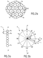
in the scanned area. Figure 3a shows a linear array 4 of seven ultrasonic
transducers 1a to 1g. The seven ultrasonic transducers may be used as emitters
and at least one of them may be controlled as a receiver after each shot.
Particularly, due to the high acoustic impedance of the air, a good power/cost
compromise can be achieved in the air with a phased array using circular
ultrasonic transducers 1a to 1g of the MA40S™ type commercialized by
MURATA MFG. CO., LTD, under a nominal frequency of 40 Hz, i.e. λ = 8,5
mm. An emitting wavelength of 8,5 mm is considered as being suitable for a
sufficient power (a scanning depth of about 10 meters) for this type of
ultrasonic transducer phased array in the air. Each ultrasonic transducer 1a to
1g has a directivity (i.e. angular range) of 100°, a detection range (scanning
depth) of 0,2 to 4 m, and a diameter of 9,9 ± 0,3 mm. As a result, the distance
d (d = 10 mm) between the centers of two adjacent transducers 1a and 1b is at
least substantially on the same order as the wavelength λ (λ = 8,5 mm) of the
emitting radiation.
-
Figure 3b shows the acoustic lobe pattern 5 obtained by controlling the
above ultrasonic transducer phased array 4 along axis AA' in a ―15° shot. The
arrow V is the propagation direction of the acoustic waves provided by each
ultrasonic transducer 1a to 1g of the phased array 4. Such an arrangement
raises a further problem. Since this physical limitation does not fulfill Shannon
rule (distance between centers of two adjacent transducers to be inferior to
λ/2), the spatial acoustic energy distribution results in a main focused energy
beam (main lobe 6) and side lobes due to the spectrum aliasing (aliasing lobe
7) and diffraction at the array aperture (diffraction lobes 8). The side lobes 7
and 8 may have high amplitudes and create interference echoes. For these
reasons, the known methods and apparatuses are focusing on increasing main
lobe 6 which is used for scanning, and on decreasing or eliminating side lobes
7 and 8.
-
In an ultrasonic transducer phased array, the directivity (power and
angle relative to the main lobe) of the side lobes depends on the number of
transducers, the excitation frequency (wavelength λ), the diameters of the
transducers (angular width of lobes) and ponderation (weighting) of the
excitation signals supplied to the transducers.
-
As stated above, λ should be about 8 to 9 mm so as to avoid signal
attenuation in air. Due to transducer/air acoustical impedance matching, the
diameters of the transducers are set to a value which ensures a sufficient power
level. On the other hand, the interference echoes may be lowered by
decreasing the distance between the transducers (i.e. increasing the angular
distances between main lobe and side lobes).
-
The problem of interference echoes due to side lobes may also be
partially electronically solved by confirmation shots or combination of two
different lobe patterns in one direction.
-
However, all known solutions lead to lower power level and/or the
operating speed and consequently to a lower scanning depth and a slower
guidance control.
-
Therefore there is an important need to develop new solutions which
can solve the above mentioned problems (speed, precision, cost) of the
different solutions without lowering the acoustic power (i.e. the scanning
distance) required for applications as robot or vehicle guidance.
-
The object of this invention is to overcome the above problems by using
an ultrasonic transducer of the type described above, in which at least the
height or the width of the outside end of the horn part is smaller than the height
or the width of the ultrasonic transducer part.
-
Advantageously, at least the height or the width of the outside end of
the horn part may be inferior to, or about, half height or half width of the
ultrasonic transducer part.
-
The section of the outside end of the horn part may be circular or
elliptic and/or may be equal to the section surface of the ultrasonic transducer
part.
-
The longitudinal symmetry axis of the horn part may be rectilinear, bent
or exponential.
-
The above ultrasonic transducer may comprise a bent acoustical mirror
towards which the outside end of the horn part is pointed.
-
Such acoustical mirror may advantageously be made of a polymer or
metal material, and may be parabolic or cylindrical.
-
The inner wall of the horn part may be smooth and the material used for
the horn part may be a polymer.
-
The outside end of the horn part may be provided with a protection grid.
-
The present invention also relates to an ultrasonic transducer phased
array which comprises a plurality of such ultrasonic transducers.
-
Advantageously, the centers of adjacent outside ends may be spaced
from each other by a distance of about, or inferior to, half the wavelength (λ/2)
of the emitted ultrasonic radiation.
-
The horn parts of the ultrasonic transducers of the above ultrasonic
transducer phased array may be configured so as to form a single acoustic
transformer element.
-
The outside ends of the horn parts of the ultrasonic transducers may be
arranged in a one-dimensional or two-dimensional array.
-
The surface defined by the outside end array may be curved.
-
The ultrasonic transducers may be controlled as ultrasonic emitters and
at least two other ultrasonic transducers may be provided and controlled as
ultrasonic receivers.
-
Other ultrasonic transducers may be provided and controlled as
receivers, which comprise an ultrasonic transducer part and a horn part flaring
towards the outside.
-
The present invention also relates to an ultrasonic detection apparatus
comprising at least one ultrasonic transducer of the above mentioned type, or
at least one ultrasonic transducer phased array of the above mentioned type,
controlled with an electronic control system.
-
Additional features and advantages of the invention will appear from
the following description in which the preferred embodiments are set forth in
detail in connection with the accompanying drawings.
- Figure 1a and 1b (already described) show a conventional ultrasonic
transducer provided with a flaring horn and an array using such ultrasonic
transducer, respectively.
- Figures 2a and 2b (already described) show another conventional
ultrasonic receiver provided with a flaring horn and an array using such
conventional ultrasonic receivers, respectively.
- Figures 3a and 3b (already described) show a known ultrasonic
transducer phased array and a corresponding acoustic lobe pattern emission in
horizontal plan, respectively.
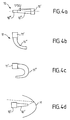
- Figures 4a to 4d show four exemplary embodiments of ultrasonic
transducers according to the present invention.
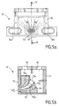
- Figures 5a and 5b show two different views of the same phased array
using ultrasonic transducers of the type of figure 4b, according to a first
embodiment of the present invention.
- Figures 6a and 6b show two different views of the same phased array
using ultrasonic transducers of the type of figure 4b, according to a second
embodiment of the present invention.
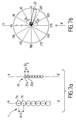
- Figures 7a and 7b show the ultrasonic transducer phased array of
Fig.3a, and its corresponding outside end phased array according to the present
invention, as well as the acoustic lobe pattern in horizontal plan obtained by
using ultrasonic transducers according to the present invention.
-
In all the above mentioned figures, the same elements keep the same
references.
-
In Fig.4a, one exemplary embodiment of an ultrasonic transducer 10
according to the invention comprises an ultrasonic transducer part 10' and a
horn part 10''. Contrary to the natural tendency of the ultrasonic transducer
field, and according to an important feature of the present invention, the end of
the horn part 10'' which is open to the observation area, i.e. the outside, (the
so-called outside end) is narrower than the end to which the ultrasonic
transducer part 10' is attached. More generally, according to the present
invention, at least one dimension of the outside end surface of the horn part
10'' is smaller than one dimension of the ultrasonic transducer part 10', i.e. of
the ultrasonic diaphragm dimension. The ultrasonic transducer part 10' may be
constituted with a circular ultrasonic transducer of the above mentioned type,
emitting acoustical waves through the horn part 10'' in its longitudinal
direction towards the outside end.
-
Accordingly, the ultrasonic transducer according to the present
invention ensures the power of the large ultrasonic transducer part, whatever
its dimensions are. As its end which is emitting and/or receiving acoustical
waves, can be of any desired dimensions smaller than the one of the ultrasonic
transducer part, the angular aperture (directivity of the ultrasonic transducer
part) can be varied in accordance to the requirements of applications.
-
The ultrasonic transducer according to the invention has further
advantages as, for instance, the protection of the ultrasonic transducer part
against outside damages, or, the use of such type of ultrasonic transducer in
phased arrays. In the latter case, the phased arrays can meet the requirements
of Shannon rule, i.e. distance between centers of adjacent ultrasonic
transducers inferior to or about half the wavelength, while having an acoustic
power which can be chosen without limitation. This is made possible as the
array is formed by the assembly of the smaller outside ends of the horns and
not by the transducers themselves. Examples of such embodiments of the
present invention are shown in Figures 5a, 5b, 6a and 6b and will be further
described.
-
Fig.4b shows another exemplary embodiment of an ultrasonic
transducer according to the present invention. The ultrasonic transducer 11 of
Fig.4b comprises a first ultrasonic transducer part 11' which may be made of
any type of ultrasonic transducer as, for instance, the above mentioned one. In
this particular embodiment, the horn part 11'' is a exponentially-bent cone.
This particular shape makes a better protection from damages coming from the
outside (water, dust, ...). The horn may have any desired curvature, in
particular it may have a U-shaped curvature as depicted in Fig.4c.
-
Fig.4d shows an ultrasonic transducer according to a particular
embodiment of the invention, in which an ultrasonic transducer 10, e.g. of the
type of Fig.4a, is combined with an acoustical mirror M reflecting the
emitting/receiving waves. Preferably, this acoustical mirror is made of a
smooth material, i.e. without any surface roughness or edges, as polymer or
metal, and bent in a parabolic or cylindrical way.
-
The inner walls of the ultrasonic transducers according to the invention
are also preferably smooth. Further, the above types of horns may be opened to
a tube-shaped part referenced as 10''' in Fig.4a, so as to ensure the directivity
of the ultrasonic transducer, e.g. by emitting the acoustical waves
perpendicularly to the surface of the outside end.
-
Thanks to its acoustic characteristics, the inventive ultrasonic transducer
is particularly well adapted for phased arrays to be used in robot or vehicle
guidance. Indeed, the spacing of half a wavelength can be respected while
keeping the power level of ultrasonic transducers used in previous solutions
and available in the market, or by using even more powerful ultrasonic
transducers, as the dimensions of the transducers become independent from the
Shannon rule. Consequently, the side lobes are eliminated or at least
significantly reduced or spread away from the main lobe, depending on the
dimensions of the outside ends of the horn parts, i.e. the distance between the
centers of two adjacent outside ends and the wavelength which is chosen.
-
Fig.5a shows a front view of an ultrasonic detection device 12 using a
two dimensional phased array 13 comprising thirteen ultrasonic transducers
11a, 11b,.. of the type of Fig.4b in which the outside ends 11'''a, 11'''b,.. of the
ultrasonic transducers 11a, 11b,.. are arranged in staggered rows (quincunx or
honeycomb). In this particular embodiment, these ultrasonic transducers are
controlled as ultrasonic emitters and the detection device is provided with two
other transducers 14a and 14b controlled as receivers. Receivers 14a and 14b
may be fixed directly onto the emission/reception surface 15 of the detection
device 12, and they can be provided with a conventional flaring horn as
illustrated in Fig.5a.
-
Fig.5b is a section view of the detection device of Fig.5a along the axis
BB'. Transducer 11a is located at the center of the phased array 13, and
transducers 11b and 11c in dotted lines are adjacent to the center transducer
11a. Each transducer 11a, 11b,.. comprises an ultrasonic transducer part 11a',
11b',.. housing an ultrasonic transducer of any known type, and a horn part
11a'', 11b'',.. guiding the emitted ultrasonic waves towards the outside at
surface 15. Transducers 11a, 11b,.. comprise a third emitting part 11a''', 11b''',..
which is tube-shaped, so that all the transducers are emitting in the same
direction. In a different embodiment, the propagation direction of the acoustic
waves generated by the transducers may be different, i.e. the surface of the
outside ends are not in the same plan, or in a curved plane. Further, some
ultrasonic transducers may be arranged so that their longitudinal axes are
inclined relative to the surface plane of the outside ends.
-
Advantageously, as illustrated in Fig.5b, the horns parts of the
ultrasonic transducers 11a, 11b,.. and/or 14a and 14b are formed in one piece
16, the so-called acoustic transformer element. This element may
advantageously be molded in one element or assembled from several pieces of
a polymer material. This decreases the cost of the whole detection system
(ultrasonic transducers, acoustic transformer element and electronic control
system). Further, the horn parts 11a'', 11b'',.. of the ultrasonic transducers 11a,
11b,.. may have different lengths. In this case the ultrasonic transducers have
to be electronically controlled so as to compensate the differences in acoustic
path lengths. Accordingly, the ultrasonic transducers may be fixed to the
acoustical transformer element 16 in a compact way so as to lower the size of
the whole device.
-
Instead of using a complete ultrasonic transducer available in the
market, mounted onto the element 16, the ultrasonic diaphragm and its two
contacts may be directly fixed on the polymer element so as to further lower
the manufacturing costs. The rear part of the polymer element 16 comprising
the ultrasonic transducers mounted herein, is accommodated in a housing 17
having openings 18 to connect the ultrasonic transducers to the electronic
control system (not shown in the figures). This type of ultrasonic detection
device can be used on a vehicle, the particular shape of the horns, e.g. bent
conical horns, preventing the ultrasonic parts to be damaged from the outside.
Further, the outside ends of the horns may advantageously be provided with
protective parts as grids.
-
Fig.6a shows a front view of a ultrasonic detection device 19 according
to another embodiment of the present invention, in which the outside ends of
the nineteen ultrasonic transducers 11a, 11b,.. are arranged in a two-dimensional
array 20 of a six branch star configuration, and in which the
ultrasonic transducers 11a, 11b,.. are controlled as emitters. In this particular
example, six other ultrasonic transducers 14a, 14b,.. are controlled as
receivers. In this example, the horn parts of the ultrasonic transducers 14a,
14b,.. have a conventional tube shape 14' enlarged at their outside ends at the
surface 22 of the detection apparatus 19 so as to focus the return echoes onto
their transducer parts 14a, 14b,...
-
Fig.6b shows a section view of the ultrasonic detection device 19 of
Fig.6a along axis CC'. The ultrasonic transducers 11a to 11c according to the
invention are advantageously formed in a single acoustic transformer element
21 as in the previous embodiment.
-
The ultrasonic transducers of the phased arrays according to the
invention may be controlled as receivers of echoes generated by one or several
ultrasonic transducers used as emitters. Then, by applying a "beam forming"
method to the memorized echo signal received by each receiver, an acoustic
image of the shot may be obtained. The principle of the beam forming method
is to apply to the echo reception, the same phase correlation made for emitting
purposes. That is, the return echo of one shot from a single ultrasonic
transducer is received by the ultrasonic transducer array, and a dephased
summation of the memorized return echo signals is made so as to obtain the
value of the return echo for each angle. For each shot, angular openings i
which are corresponding each to a time delay Δi , are electronically created for
different virtual angles, creating a reception directivity, and, in the particular
case of a one-dimensional configuration of k receivers Rj(1<j<k) (e.g. of the type
of Fig.7a in which k=7), the scanning is achieved by calculation of the
amplitude A for each angle i , i.e. the summation of the dephased echo signal
amplitudes SRj :
A( i ) = SR1 (t) + SR2 (t+Δi ) + SR3 (t+2.Δi ) +...+ SRk (t+(k-1).Δi ),
by checking the maximum of the amplitude A( i ) for different angles i , the
target angle is identified. Each target angle corresponds to one time delay. The
addition of these individual time delays produces an unambiguous indication
of the absolute angle under which the reflecting obstacle is seen from the
receivers. The beam forming method may be applied to any two or three
dimensional transducer arrays.
-
Advantageously, an electronic calibration of the array in terms of phase
and power may be made before each use of the ultrasonic phased array, so as
to compensate the geometrical defects in the design and dimensions of the
horns.
-
Further, due to the geometrical flexibility of the horns, a geometrical
ponderation (weighting) of the secondary lobes may be easily achieved in
parallel to the electronic ponderation of the excitation signals as mentioned
above, by controlling the shapes and diameters of the outside ends of the
horns, and the spacing between them.
-
In a modified implementation of the invention, the horn part of the
transducer may be designed so that the section of the outside ends is oval, or
elongated, at least the small diameter being inferior to, or about, half
wavelength. Advantageously, the section surface may be equal to the surface
of the ultrasonic diaphragm of the ultrasonic transducer. A detection device of
the above described type may use such ultrasonic transducers so as to get a
focused directivity in one plane and a larger one in the plane perpendicular to
the first one.
-
Another modified ultrasonic detection apparatus may use one transducer
supplying several horn parts so as to decrease the number of ultrasonic
transducers, in accordance with the requirements of the application.
-
Several ultrasonic detection devices according to the invention
controlled by a unique electronic control system may be implemented in a
vehicle for obstacle detection or a robot for guidance purposes, or in an interior
space for the purpose of detecting the presence of an intruder.
-
Fig.7a shows the conventional ultrasonic transducer phased array of
Fig.3a (left) and its corresponding outside ends 25 (right) by using ultrasonic
transducers according to the invention. In this particular case taken as an
example, the acoustic transformer is designed so that the distance d' between
two outside ends 25a and 25b is half the distance d between two adjacent
transducers 1a and 1b. By using the ultrasonic transducers as described above,
the distance d' may be about 4,5 mm which is in the order of half wave length,
λ/2 = 4,25 mm.
-
Fig.7b shows the acoustic lobe pattern obtainable by the phased array of
Fig.3a using ultrasonic transducers according to the invention. This acoustic
lobe pattern has to be compared with the acoustic lobe pattern of Fig.3b
obtained with prior art ultrasonic transducers. As shown in Fig.7b, the side
lobes 24 has been lowered and the directivity of main lobe 23 is increased.
-
For instance, the implementation of the present invention can perform
indoor robot navigation in autonomous way. By using prior art ultrasonic
transducers of the MA40S3 type in the ultrasonic transducer elements
according to the invention, a main lobe with a thickness of 20° to 30° (at ―3db)
may be obtained, the accuracy as for the distance is about 1cm, the accuracy as
for the angle is about 2°, the operation range is from 0,5 m to 10 m, the
response time is from 50 to 500 ms, and electronic scanning is ± 90° of the
observation area.
-
The ultrasonic transducers and ultrasonic detection devices according to
the invention may also be employed in a solid medium (e.g. for non-destructive
testing) and in a liquid medium, e.g. water, but the invention is
particularly well-adapted to be used in a gaseous medium as, for instance, air.
-
In case of using such ultrasonic transducers in a solid or liquid medium,
the horn parts may be full (i.e. solid) and independent from each others.
-
Only a few ultrasonic transducers, easily available in the market, are
necessary and the acoustical transformer for ultrasonic transducer phased array
may be simply manufactured and compacted with inexpensive materials.
Consequently the whole improved ultrasonic detection system has a compact
size, low cost and provides a protection against the dirt and rain. Further, a
system according to the invention is not sensitive to parasitic light sources and
can operate in the dark.
-
The present invention has a large range of applications. For instance, it
can be used for vehicles (back sonar system, automatic car parking, collision
protection, passenger detection), in industry (automatic parts distribution,
automatic packaging, remote control of objects on assembly lines, cleaning
robots, etc.), at home (automatic floor cleaning) and for public health (sonar
for blind persons, movement detection for elderly person).