EP0928488B1 - Gap forming and cooling structure for a nuclear reactor - Google Patents
Gap forming and cooling structure for a nuclear reactor Download PDFInfo
- Publication number
- EP0928488B1 EP0928488B1 EP96932069A EP96932069A EP0928488B1 EP 0928488 B1 EP0928488 B1 EP 0928488B1 EP 96932069 A EP96932069 A EP 96932069A EP 96932069 A EP96932069 A EP 96932069A EP 0928488 B1 EP0928488 B1 EP 0928488B1
- Authority
- EP
- European Patent Office
- Prior art keywords
- vessel
- reactor
- gap
- lower head
- concave
- Prior art date
- Legal status (The legal status is an assumption and is not a legal conclusion. Google has not performed a legal analysis and makes no representation as to the accuracy of the status listed.)
- Expired - Lifetime
Links
- 238000001816 cooling Methods 0.000 title claims description 22
- 239000002826 coolant Substances 0.000 claims description 29
- XLYOFNOQVPJJNP-UHFFFAOYSA-N water Substances O XLYOFNOQVPJJNP-UHFFFAOYSA-N 0.000 claims description 21
- 230000014759 maintenance of location Effects 0.000 claims description 10
- 239000011162 core material Substances 0.000 description 59
- 238000013461 design Methods 0.000 description 7
- XLYOFNOQVPJJNP-ZSJDYOACSA-N Heavy water Chemical compound [2H]O[2H] XLYOFNOQVPJJNP-ZSJDYOACSA-N 0.000 description 6
- 230000035515 penetration Effects 0.000 description 6
- 230000000694 effects Effects 0.000 description 5
- 238000009835 boiling Methods 0.000 description 4
- 238000006243 chemical reaction Methods 0.000 description 4
- 238000002844 melting Methods 0.000 description 4
- 230000008018 melting Effects 0.000 description 4
- 238000000034 method Methods 0.000 description 3
- 238000013021 overheating Methods 0.000 description 3
- 238000011161 development Methods 0.000 description 2
- 238000010438 heat treatment Methods 0.000 description 2
- 230000001788 irregular Effects 0.000 description 2
- 239000000463 material Substances 0.000 description 2
- 230000007246 mechanism Effects 0.000 description 2
- 230000035939 shock Effects 0.000 description 2
- OKTJSMMVPCPJKN-UHFFFAOYSA-N Carbon Chemical compound [C] OKTJSMMVPCPJKN-UHFFFAOYSA-N 0.000 description 1
- 230000006399 behavior Effects 0.000 description 1
- 239000000919 ceramic Substances 0.000 description 1
- 239000002131 composite material Substances 0.000 description 1
- 238000010276 construction Methods 0.000 description 1
- 230000007797 corrosion Effects 0.000 description 1
- 238000005260 corrosion Methods 0.000 description 1
- 230000007423 decrease Effects 0.000 description 1
- 230000007123 defense Effects 0.000 description 1
- 238000003745 diagnosis Methods 0.000 description 1
- 239000012530 fluid Substances 0.000 description 1
- 239000007789 gas Substances 0.000 description 1
- 229910002804 graphite Inorganic materials 0.000 description 1
- 239000010439 graphite Substances 0.000 description 1
- 238000007689 inspection Methods 0.000 description 1
- 238000009434 installation Methods 0.000 description 1
- 229910001338 liquidmetal Inorganic materials 0.000 description 1
- 238000012423 maintenance Methods 0.000 description 1
- 239000000155 melt Substances 0.000 description 1
- 239000002184 metal Substances 0.000 description 1
- 229910052751 metal Inorganic materials 0.000 description 1
- 150000002739 metals Chemical class 0.000 description 1
- 239000003758 nuclear fuel Substances 0.000 description 1
- 230000002285 radioactive effect Effects 0.000 description 1
- 239000012857 radioactive material Substances 0.000 description 1
- 239000004576 sand Substances 0.000 description 1
- 239000002356 single layer Substances 0.000 description 1
- 239000003351 stiffener Substances 0.000 description 1
- 239000000126 substance Substances 0.000 description 1
- 238000012546 transfer Methods 0.000 description 1
- 230000001052 transient effect Effects 0.000 description 1
Images



Classifications
-
- G—PHYSICS
- G21—NUCLEAR PHYSICS; NUCLEAR ENGINEERING
- G21C—NUCLEAR REACTORS
- G21C9/00—Emergency protection arrangements structurally associated with the reactor, e.g. safety valves provided with pressure equalisation devices
- G21C9/016—Core catchers
-
- Y—GENERAL TAGGING OF NEW TECHNOLOGICAL DEVELOPMENTS; GENERAL TAGGING OF CROSS-SECTIONAL TECHNOLOGIES SPANNING OVER SEVERAL SECTIONS OF THE IPC; TECHNICAL SUBJECTS COVERED BY FORMER USPC CROSS-REFERENCE ART COLLECTIONS [XRACs] AND DIGESTS
- Y02—TECHNOLOGIES OR APPLICATIONS FOR MITIGATION OR ADAPTATION AGAINST CLIMATE CHANGE
- Y02E—REDUCTION OF GREENHOUSE GAS [GHG] EMISSIONS, RELATED TO ENERGY GENERATION, TRANSMISSION OR DISTRIBUTION
- Y02E30/00—Energy generation of nuclear origin
- Y02E30/30—Nuclear fission reactors
Definitions
- This invention relates to a gap forming and retention structures for protection of the nuclear reactor vessel lower head from rupture in core meltdown accident.
- This invention concerned with nuclear reactors, is to introduce at the lower head of the reactor vessel a gap forming structure by which a coolable geometry is maintained to prevent overheating and ultimately failing of the lower head wall due to accumulated molten core debris in the event of a core meltdown accident.
- the lower head herein refers to a concave paraboloidal or cylindrical vessel that comprises as the reactor fluid boundary. Should such a severe accident occur, the core material inside the reactor vessel may melt due to overheating and then relocate down to the vessel lower head. In this event, direct contact by the vessel lower head with molten core material may heat up and deform the metallic reactor vessel lower head causing it to rupture, thereby posing a risk of massive release of radioactive materials.
- the structure of this invention creates an engineered gap which prevents the molten core material from directly contacting the vessel inner surface such that: firstly, it prevents rapid heating of the reactor vessel lower head; secondly, it helps achieve a defense against severe accidents by the secured water cooling effect inside the gap and hence prevents the reactor vessel lower head from failing.
- ex-vessel catcher was proposed by M. J. Driscoll and F. L. Bowman (M. I. T.) [U. S. Patent No. 4,113,560].
- the molten core debris solidifies with ex-vessel structures (graphite, sand etc.).
- the ex-vessel catcher can confine and isolate molten core debris within itself to block further reaction with the containment structures. It is intended to avoid the generation of heat and gases from the reaction of the molten core debris with containment floor concrete and prevent the massive escape of radioactive molten core debris through the bottom concrete.
- GB-A-2 236 210 describes a core catcher for a nuclear reactor positioned below a domed end of the pressure vessel of the nuclear reactor, the core catcher being located in a containment structure filled with water.
- the core catcher In case of a reactor core meltdown molten core debris drops down into the domed end of the reactor vessel, so that overheating and finally failing of the domed end will occur.
- the molten debris will drop down into the core catcher.
- the core catcher comprises a multilayer structure which prevents the core catcher from being damaged by the hot molten debris, the latter being cooled by the water inside the containment structure.
- the known arrangement has the disadvantage in that a large amount of coolant is required. Despite this large amount of coolant, the lower end of the vessel is not effectively cooled so that there is the risk that the lower end fails.
- a gap forming and retention structure for use with a nuclear reactor vessel having a reactor core assembly positioned above reactor vessel lower head having an external surface and with a coolant circulating in the reactor vessel, said structure comprising:
- the present invention is designed to incorporate structures that provide a sufficient gap which should maintain coolable geometry proximate the bottom of the reactor vessel keep it from melting.
- This invention can be applied to all water cooled reactors to function in a passive manner in conjunction with existing engineered safety features as well as natural circulation routes.
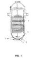
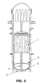
- the central core (1) is a nuclear fuel region where the coolant flow removes the nuclear reaction heat. If an accident takes place and cooling capacity decreases, and neighboring structures may melt down and accumulate on the lower head.
- the gap structure (3) will prevent the molten core from direct contact with the lower head (2) inner surface.
- instrumentation /control nozzles penetrate the reactor vessel lower head (2) and are welded to the vessel inner surface.
- the gap structure (3) will be installed at the bottom of the lower core support structures at an appropriate gap (5) or distance from the reactor vessel bottom and have sufficient strength and heat resistance to maintain coolable geometry and also support the dead weight of the molten core during core material meltdown accidents.
- the minimum gap size taking into account the boiling heat transfer and structural behaviors is determined to be about 2 centimeters.
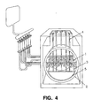
- the gap structure(3) is of a parabolic or concave shape and has vertical flow holes(6). It (3) preferably covers the entire reactor vessel lower head (2) to prevent the molten core from flowing into the gap. The change of coolant flow distribution in the lower plenum due to the gap structure (3) must be minimized during normal operation or design transient of light water reactors (LWRs).
- Figure 6 shows that the gap structure (3) is welded (11) or fastened to the lower core structures or instrumentation/control penetration (4) structure in the vessel lower head. Additional support structure may be attached to it (3) to resist deformation induced by heavy load.
- the means are used for spacing apart and maintaining the concave vessel in a spaced apart condition relative to the reactor vessel lower head such that a gap is formed and maintained between the concave vessel and the reactor vessel lower head in the event of a reactor core meltdown. These means enable the coolant circulating in the reactor vessel to circulate within the gap thereby preventing direct contact of the molten core debris with the reactor vessel lower head and removing heat from the molten core debris.
- Such coolant circulation ensures that the structural integrity of the reactor vessel lower head is maintained during the reception and retention of the molten core debris by the concave vessel.
- the means for spacing apart and maintaining the concave vessel in a spaced apart condition relative to the reactor vessel lower head include support beams (10A), deformation-limiting foot (9) secured to the concave vessel and structural stiffeners (10B).
- the gap structure (3) of this invention would catch the molten core material so as to avoid direct contact with the vessel and to enable removal of the heat from the relocated core material by the water coolant circulating in the gap (5) between the vessel and the debris.
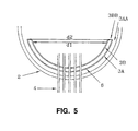
- each gap structure (3) is illustrated in a single layer, however, multilayer gap structures may also be used where desired, as shown in Fig. 5.
- the concave vessel of the gap forming and retention structure defines a first concave vessel (3A) and a second concave vessel (3B), wherein the first concave vessel (3A) is spaced apart from the reactor vessel lower head (2) to form a first gap (3AA) and the second concave vessel (3B) is spaced apart from the first concave vessel (3A) to form a second gap (3BB).
- the diameter d1 of the second concave vessel 3B is less than the diameter d2 of the first concave vessel (3A) and the gap between vessels (3BB) and between the first concave vessel and the reactor vessel lower head (3AA) are independently uniformly or evenly spaced apart.
- a plurality of concave vessels may be positioned in the reactor vessel with the first being proximate the reactor vessel lower head and with the upper vessels having consecutively smaller diameters.
- Fig. 5 the first and second concave vessels (3A,3B) are secured to the structural guide sleeves (7) which house the instrumentation/control penetration structures (4) (not illustrated).
- Flow holes (6) distributed in each gap structure (3) may be introduced to reduce the temperature difference between the gap water and the bulk water in the lower plenum during normal operation and design transients. The flow hole length-to-diameter ratio exceeds so that the molten core debris is not expected to penetrate through. The relocated molten core may thermally attack the instrumentation/control penetration (4) to render further diagnosis of the core state difficult.
- the gap structure (3) of this invention should be made of materials that are both durable and tolerant to thermal and mechanical shock loads. Corrosion resistant metals possibly incorporating ceramic and/or composite materials would be expected to qualify for the required resistance. Cooling fins may be attached to the gap structure (3) to enhance the cooling capacity.
- Figs. 1, 2, 3, and 4 show the in-vessel gap structures
- Fig. 7 shows an ex-vessel gap structure (3) installed outside the vessel lower head (2) according to the present invention.
- required coolant would be supplied from a coolant reservoir (15) during the accident via a control valve (16) and coolant feed tube (17).
- Both in-vessel and ex-vessel gap structures may be installed such that they will not interfere with vessel inspection and maintenance.
- a plurality of ex-vessel gap structures could be utilized (not shown for sake of brevity) if desired.
- the external gap forming and retention structure for use with a nuclear reactor vessel having a reactor core assembly positioned above a reactor vessel lower head and with a coolant circulating in the reactor vessel, comprises a concave vessel externally positioned below and spaced apart from the exterior surface of the reactor vessel lower head such that a gap is formed between the exterior surface of the reactor vessel lower head and the concave vessel.
- a coolant supply means supplies coolant to the gap in the event of a reactor core meltdown to enable removal of heat from the reactor vessel lower head heated by molten core debris from the reactor core assembly in the event of a reactor core meltdown thereby maintaining structural integrity of the reactor vessel lower head during the reception and retention of the molten core debris by the reactor vessel.
- the coolant supply means further includes a control valve for controlling the rate of coolant flow into the gap.
- Cooling fins may also be secured to the lower head of the reactor vessel to aid in heat removal by the coolant as it flows in the gap.
- Fig. 8 illustrates severe accident development without the gap structures
- Fig. 9 illustrates the accident arrest with the help of the gap structure according to figures 1 to 6.
- numbers 12, 13, and 14 represent water coolant (12), molten core debris (13) and failed vessel lower head (14), respectively.
- Fig. 10 (A) shows a top view
- Fig. 10 (B) shows a cross-sectional view
- Fig. 10 (C) shows a plan view of the gap structure (3) which is applicable to PWR, flow-channel type PWR (VVER-type), and BWR.
- the gap structure plan view of Fig. 10 (C) is illustrated with grid lines to enhance three-dimensional display effect
- This figure also shows structural guide sleeves (7) for the instrumentation/control penetration.
- Fig. 10 (C) is illustrated with grid lines to enhance three-dimensional display effect
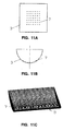
- FIG. 11(A) shows a top view
- Fig. 11(B) shows a cross-sectional view
- Fig. 11(C) shows a plan view of the gap structure of the present invention (3) which is applicable to a pressurized heavy water reactor (CANDU-type).
- the plan view, Fig. 11(C) is illustrated with grid lines to enhance three-dimensional display effect.
- This figure also shows structural guide sleeves (7) for the instrumentation/control penetration.
- Design of the next generation nuclear reactors is required to have provisions for the protection against severe accidents. Proposed designs for this purpose, in the case of light water reactors, include two main features: namely, reactor cavity flooding method and advanced containment cooling method. These methods of protection against severe accidents would require large and costly facilities.
- the gap structures of this invention provide vessel protection with relatively simple structural installations and can function largely in a passive manner.
Landscapes
- Physics & Mathematics (AREA)
- Engineering & Computer Science (AREA)
- Plasma & Fusion (AREA)
- General Engineering & Computer Science (AREA)
- High Energy & Nuclear Physics (AREA)
- Structure Of Emergency Protection For Nuclear Reactors (AREA)
Description
that is applicable for a pressurized water reactor (PWR), a flow-channel type pressurized water reactor (VVER-type), and a boiling water reactor (BWR).
that is applicable for a pressurized heavy water reactor (CANDU-type).
Claims (4)
- A gap forming and cooling structure for use with a water cooled nuclear reactor vessel having a reactor core assembly (1) positioned above a reactor vessel lower head (2) having an external surface and with a coolant circulating in the reactor vessel, said structure comprising:characterized in that a coolant supply means (15, 16) for supplying coolant to said gap (5) in the event of a reactor core meltdown is provided to enable removal of heat from said reactor vessel lower head (2) heated by molten core debris from said reactor core assembly in the event of a reactor core meltdown thereby maintaining structural integrity of said reactor vessel lower head (2) during the reception and retention of said molten core debris by said reactor vessel.a concave vessel (3) externally positioned below and spaced apart from said external surface of said reactor vessel lower head (2);means for spacing apart and maintaining said concave vessel (3) in a spaced apart condition relative to said external surface of said reactor vessel lower head (2) such that a gap (5) is formed and maintained between said concave vessel (3) and said external surface of said reactor vessel lower head (2) in the event of a reactor core meltdown;
- The gap forming and cooling structure of claim 1, wherein said coolant supply means further includes a control valve (16) for controlling the rate of coolant flow into said gap.
- The gap forming and cooling structure of claim 1, wherein said concave vessel (3) defines a first concave vessel and a second concave vessel, wherein said first concave vessel is spaced apart from said external surface of said reactor vessel lower head to form a first gap and said second concave vessel is spaced apart from said first concave vessel to form a second gap; and
a second coolant supply means for supplying coolant to said second gap in the event of a reactor core meltdown to enable the removal of heat from said first concave vessel heated by molten core debris from said reactor core assembly in the event of a reactor core meltdown thereby maintaining structural integrity of said reactor vessel lower head during the reception and retention of said molten core debris by said reactor vessel. - The gap forming and cooling structure of claim 3, wherein said a first concave vessel is internally positioned below said reactor core assembly proximate said reactor vessel lower head, and said second concave vessel is spaced apart from said external surface of said reactor vessel lower head.
Applications Claiming Priority (1)
| Application Number | Priority Date | Filing Date | Title |
|---|---|---|---|
| PCT/KR1996/000166 WO1998013832A1 (en) | 1996-09-25 | 1996-09-25 | Gap structure for nuclear reactor vessel |
Publications (2)
| Publication Number | Publication Date |
|---|---|
| EP0928488A1 EP0928488A1 (en) | 1999-07-14 |
| EP0928488B1 true EP0928488B1 (en) | 2002-06-05 |
Family
ID=19449087
Family Applications (1)
| Application Number | Title | Priority Date | Filing Date |
|---|---|---|---|
| EP96932069A Expired - Lifetime EP0928488B1 (en) | 1996-09-25 | 1996-09-25 | Gap forming and cooling structure for a nuclear reactor |
Country Status (6)
| Country | Link |
|---|---|
| US (1) | US6195405B1 (en) |
| EP (1) | EP0928488B1 (en) |
| JP (1) | JP3263402B2 (en) |
| AU (1) | AU7098196A (en) |
| DE (1) | DE69621656D1 (en) |
| WO (1) | WO1998013832A1 (en) |
Cited By (2)
| Publication number | Priority date | Publication date | Assignee | Title |
|---|---|---|---|---|
| DE19949583B4 (en) * | 1998-10-14 | 2008-10-02 | Commissariat à l'Energie Atomique | Water nuclear reactor with a deformable internal structures containing catch |
| RU2750230C1 (en) * | 2020-11-10 | 2021-06-24 | Акционерное Общество "Атомэнергопроект" | Localization and cooling system for core melt of nuclear reactor |
Families Citing this family (13)
| Publication number | Priority date | Publication date | Assignee | Title |
|---|---|---|---|---|
| FR2763168B1 (en) * | 1997-05-06 | 1999-11-05 | Commissariat Energie Atomique | NUCLEAR WATER REACTOR, OF WHICH THE TANK CONTAINS A DEVICE FOR RECOVERING THE HEART AFTER ITS ACCIDENTAL FUSION |
| DE19846057B4 (en) * | 1998-10-07 | 2004-04-29 | Forschungszentrum Jülich GmbH | Device for cooling and protecting a reactor pressure vessel in the event of meltdowns |
| FR2784784B1 (en) * | 1998-10-14 | 2000-12-01 | Commissariat Energie Atomique | NUCLEAR WATER REACTOR WITH INTEGRATED RECEPTACLE |
| FR2840100B1 (en) * | 2002-05-24 | 2005-07-08 | Technicatome | NUCLEAR REACTOR EQUIPPED WITH A PASSIVE DEVICE FOR HOLDING THE HEART IN CASES OF TEMPERATURE RAISING |
| KR100597723B1 (en) * | 2004-02-10 | 2006-07-10 | 한국원자력연구소 | Core melt passive cooling and confinement |
| JP5582858B2 (en) * | 2010-04-23 | 2014-09-03 | 株式会社東芝 | Core melt holding structure |
| CN102969033B (en) * | 2012-10-25 | 2015-04-15 | 清华大学 | Boiling heat-exchange reinforced wall-attached orifice plate assembly shell component |
| US10147506B2 (en) * | 2014-04-03 | 2018-12-04 | Bwxt Mpower, Inc. | Conformal core cooling and containment structure |
| KR102216695B1 (en) * | 2018-09-03 | 2021-02-18 | 한국원자력연구원 | Cooling apparatus for molten core |
| KR102649036B1 (en) | 2022-03-14 | 2024-03-18 | 한국수력원자력 주식회사 | Small modular reactor cooling apparatus and cooling method |
| CN115938619B (en) * | 2022-11-22 | 2024-01-19 | 上海核工程研究设计院股份有限公司 | Pressure vessel with retention basket for high-power reactor and reactor system |
| CN116386910B (en) * | 2022-11-28 | 2024-02-13 | 上海核工程研究设计院股份有限公司 | Reactor pressure vessel and method for improving retention effectiveness of reactor core melt |
| CN115862908B (en) * | 2023-01-30 | 2024-01-12 | 上海核工程研究设计院股份有限公司 | Experimental device for in-pile retention basket under severe accident |
Family Cites Families (12)
| Publication number | Priority date | Publication date | Assignee | Title |
|---|---|---|---|---|
| US4036688A (en) * | 1975-04-09 | 1977-07-19 | The United States Of America As Represented By The United States Energy Research And Development Administration | Apparatus for controlling molten core debris |
| US4113560A (en) | 1975-07-14 | 1978-09-12 | Massachusetts Institute Of Technology | Core catcher for nuclear reactor core meltdown containment |
| DE2535729C2 (en) * | 1975-08-11 | 1985-05-02 | INTERATOM GmbH, 5060 Bergisch Gladbach | Floor cooler for the floor pan of a nuclear reactor |
| FR2395567A1 (en) * | 1977-06-23 | 1979-01-19 | Commissariat Energie Atomique | HEART RECOVERY DEVICE FOR FAST NEUTRON NUCLEAR REACTOR |
| US4310385A (en) * | 1980-01-03 | 1982-01-12 | Rosewell Michael P | Emergency deployable core catcher |
| US4442065A (en) * | 1980-12-01 | 1984-04-10 | R & D Associates | Retrofittable nuclear reactor core catcher |
| US4412969A (en) | 1982-03-09 | 1983-11-01 | Tilbrook Roger W | Combination pipe rupture mitigator and in-vessel core catcher |
| US4859402A (en) * | 1987-09-10 | 1989-08-22 | Westinghouse Electric Corp. | Bottom supported liquid metal nuclear reactor |
| GB2236210B (en) | 1989-08-30 | 1993-06-30 | Rolls Royce & Ass | Core catchers for nuclear reactors |
| FR2683375B1 (en) | 1991-11-06 | 1994-01-07 | Commissariat A Energie Atomique | NUCLEAR REACTOR EQUIPPED WITH A HEART RECOVERY DEVICE, AFTER ITS ACCIDENTAL MERGER. |
| DE4211030C2 (en) * | 1992-04-02 | 1994-03-10 | Siemens Ag | Nuclear reactor plant with a water-cooled reactor and method for operating the same |
| WO1994029877A1 (en) * | 1993-06-08 | 1994-12-22 | Siemens Aktiengesellschaft | Closing device for initiating cooling for a core melt |
-
1996
- 1996-09-25 DE DE69621656T patent/DE69621656D1/en not_active Expired - Lifetime
- 1996-09-25 WO PCT/KR1996/000166 patent/WO1998013832A1/en not_active Ceased
- 1996-09-25 AU AU70981/96A patent/AU7098196A/en not_active Abandoned
- 1996-09-25 JP JP51551798A patent/JP3263402B2/en not_active Expired - Lifetime
- 1996-09-25 EP EP96932069A patent/EP0928488B1/en not_active Expired - Lifetime
- 1996-09-25 US US09/202,982 patent/US6195405B1/en not_active Expired - Fee Related
Cited By (3)
| Publication number | Priority date | Publication date | Assignee | Title |
|---|---|---|---|---|
| DE19949583B4 (en) * | 1998-10-14 | 2008-10-02 | Commissariat à l'Energie Atomique | Water nuclear reactor with a deformable internal structures containing catch |
| RU2750230C1 (en) * | 2020-11-10 | 2021-06-24 | Акционерное Общество "Атомэнергопроект" | Localization and cooling system for core melt of nuclear reactor |
| WO2022103301A1 (en) * | 2020-11-10 | 2022-05-19 | Акционерное Общество "Атомэнергопроект" | System for confining and cooling melt from the core of a nuclear reactor |
Also Published As
| Publication number | Publication date |
|---|---|
| EP0928488A1 (en) | 1999-07-14 |
| US6195405B1 (en) | 2001-02-27 |
| DE69621656D1 (en) | 2002-07-11 |
| JP3263402B2 (en) | 2002-03-04 |
| AU7098196A (en) | 1998-04-17 |
| WO1998013832A1 (en) | 1998-04-02 |
Similar Documents
| Publication | Publication Date | Title |
|---|---|---|
| US5307390A (en) | Corium protection assembly | |
| US6195405B1 (en) | Gap structure for nuclear reactor vessel | |
| CA2971132C (en) | Water-cooled water-moderated nuclear reactor core melt cooling and confinement system | |
| US5057271A (en) | Protection system for the basemat reactor containment buildings in nuclear power stations | |
| US3935063A (en) | Emergency heat removal system for a nuclear reactor | |
| EP3236473B1 (en) | System for confining and cooling melt from the core of a nuclear reactor | |
| EP3236474B1 (en) | Confinement and cooling of melt from the core of a nuclear reactor | |
| JP3118489B2 (en) | Reactor with equipment for recovery of core after accidental meltdown of reactor | |
| WO2015153862A2 (en) | Conformal core cooling and containment structure | |
| US20120051485A1 (en) | Corium cooling promoting apparatus and containment | |
| JP2000504119A (en) | Clearance structure for reactor vessel | |
| JPH10319166A (en) | Water reactor containing core recovery device operating in accidental meltdown | |
| JP2009052951A (en) | Core melt cooling device and reactor containment vessel | |
| US5333156A (en) | Nuclear fuel assembly with an integrated passive safety device | |
| EP3067895B1 (en) | Primary containment vessel | |
| RU2165108C2 (en) | Protective system of protective shell of water-cooled reactor plant | |
| RU100326U1 (en) | DEVICE FOR THE WALL OF THE HEAT EXCHANGER HOUSING | |
| KR0169864B1 (en) | Clearance structure for protection of puncture of the lower head of reactor on the burst of the nuclear reactor core | |
| CN1150566C (en) | Gap structure for nuclear reactor core pressure vessel | |
| US20020003852A1 (en) | Ex-vessel core melt retention device preventing molten core concrete interaction | |
| Pfeffer et al. | Integrated Fast Reactor: PRISM |
Legal Events
| Date | Code | Title | Description |
|---|---|---|---|
| PUAI | Public reference made under article 153(3) epc to a published international application that has entered the european phase |
Free format text: ORIGINAL CODE: 0009012 |
|
| 17P | Request for examination filed |
Effective date: 19990420 |
|
| AK | Designated contracting states |
Kind code of ref document: A1 Designated state(s): DE FR |
|
| 17Q | First examination report despatched |
Effective date: 20001218 |
|
| RTI1 | Title (correction) |
Free format text: GAP FORMING AND COOLING STRUCTURE FOR A NUCLEAR REACTOR |
|
| RTI1 | Title (correction) |
Free format text: GAP FORMING AND COOLING STRUCTURE FOR A NUCLEAR REACTOR |
|
| GRAG | Despatch of communication of intention to grant |
Free format text: ORIGINAL CODE: EPIDOS AGRA |
|
| GRAG | Despatch of communication of intention to grant |
Free format text: ORIGINAL CODE: EPIDOS AGRA |
|
| GRAG | Despatch of communication of intention to grant |
Free format text: ORIGINAL CODE: EPIDOS AGRA |
|
| GRAH | Despatch of communication of intention to grant a patent |
Free format text: ORIGINAL CODE: EPIDOS IGRA |
|
| GRAH | Despatch of communication of intention to grant a patent |
Free format text: ORIGINAL CODE: EPIDOS IGRA |
|
| GRAA | (expected) grant |
Free format text: ORIGINAL CODE: 0009210 |
|
| AK | Designated contracting states |
Kind code of ref document: B1 Designated state(s): DE FR |
|
| REF | Corresponds to: |
Ref document number: 69621656 Country of ref document: DE Date of ref document: 20020711 |
|
| PG25 | Lapsed in a contracting state [announced via postgrant information from national office to epo] |
Ref country code: DE Free format text: LAPSE BECAUSE OF FAILURE TO SUBMIT A TRANSLATION OF THE DESCRIPTION OR TO PAY THE FEE WITHIN THE PRESCRIBED TIME-LIMIT Effective date: 20020906 |
|
| ET | Fr: translation filed | ||
| PLBE | No opposition filed within time limit |
Free format text: ORIGINAL CODE: 0009261 |
|
| STAA | Information on the status of an ep patent application or granted ep patent |
Free format text: STATUS: NO OPPOSITION FILED WITHIN TIME LIMIT |
|
| 26N | No opposition filed |
Effective date: 20030306 |
|
| REG | Reference to a national code |
Ref country code: FR Ref legal event code: TP |
|
| PGFP | Annual fee paid to national office [announced via postgrant information from national office to epo] |
Ref country code: FR Payment date: 20140906 Year of fee payment: 19 |
|
| REG | Reference to a national code |
Ref country code: FR Ref legal event code: ST Effective date: 20160531 |
|
| PG25 | Lapsed in a contracting state [announced via postgrant information from national office to epo] |
Ref country code: FR Free format text: LAPSE BECAUSE OF NON-PAYMENT OF DUE FEES Effective date: 20150930 |