EP0928010B1 - Coil assembly useful in solenoid valves - Google Patents
Coil assembly useful in solenoid valves Download PDFInfo
- Publication number
- EP0928010B1 EP0928010B1 EP98310684A EP98310684A EP0928010B1 EP 0928010 B1 EP0928010 B1 EP 0928010B1 EP 98310684 A EP98310684 A EP 98310684A EP 98310684 A EP98310684 A EP 98310684A EP 0928010 B1 EP0928010 B1 EP 0928010B1
- Authority
- EP
- European Patent Office
- Prior art keywords
- housing
- flux tube
- coil
- coupling
- annular
- Prior art date
- Legal status (The legal status is an assumption and is not a legal conclusion. Google has not performed a legal analysis and makes no representation as to the accuracy of the status listed.)
- Expired - Lifetime
Links
- 230000004907 flux Effects 0.000 claims description 58
- 230000008878 coupling Effects 0.000 claims description 34
- 238000010168 coupling process Methods 0.000 claims description 34
- 238000005859 coupling reaction Methods 0.000 claims description 34
- 238000000034 method Methods 0.000 claims description 7
- 239000000696 magnetic material Substances 0.000 claims description 6
- 239000000463 material Substances 0.000 claims description 6
- 238000004519 manufacturing process Methods 0.000 claims description 2
- 230000000712 assembly Effects 0.000 description 7
- 238000000429 assembly Methods 0.000 description 7
- 230000000694 effects Effects 0.000 description 7
- 238000004891 communication Methods 0.000 description 3
- 238000006073 displacement reaction Methods 0.000 description 2
- 230000007257 malfunction Effects 0.000 description 2
- 230000000717 retained effect Effects 0.000 description 2
- IQVNEKKDSLOHHK-FNCQTZNRSA-N (E,E)-hydramethylnon Chemical compound N1CC(C)(C)CNC1=NN=C(/C=C/C=1C=CC(=CC=1)C(F)(F)F)\C=C\C1=CC=C(C(F)(F)F)C=C1 IQVNEKKDSLOHHK-FNCQTZNRSA-N 0.000 description 1
- RYGMFSIKBFXOCR-UHFFFAOYSA-N Copper Chemical compound [Cu] RYGMFSIKBFXOCR-UHFFFAOYSA-N 0.000 description 1
- 241001522296 Erithacus rubecula Species 0.000 description 1
- CWYNVVGOOAEACU-UHFFFAOYSA-N Fe2+ Chemical compound [Fe+2] CWYNVVGOOAEACU-UHFFFAOYSA-N 0.000 description 1
- 229910000831 Steel Inorganic materials 0.000 description 1
- 230000008859 change Effects 0.000 description 1
- 229910052802 copper Inorganic materials 0.000 description 1
- 239000010949 copper Substances 0.000 description 1
- 239000012530 fluid Substances 0.000 description 1
- 230000017525 heat dissipation Effects 0.000 description 1
- 238000009434 installation Methods 0.000 description 1
- 230000014759 maintenance of location Effects 0.000 description 1
- 230000002093 peripheral effect Effects 0.000 description 1
- 230000008569 process Effects 0.000 description 1
- 238000007789 sealing Methods 0.000 description 1
- 125000006850 spacer group Chemical group 0.000 description 1
- 239000010959 steel Substances 0.000 description 1
- 230000002277 temperature effect Effects 0.000 description 1
Images


Classifications
-
- H—ELECTRICITY
- H01—ELECTRIC ELEMENTS
- H01F—MAGNETS; INDUCTANCES; TRANSFORMERS; SELECTION OF MATERIALS FOR THEIR MAGNETIC PROPERTIES
- H01F7/00—Magnets
- H01F7/06—Electromagnets; Actuators including electromagnets
- H01F7/08—Electromagnets; Actuators including electromagnets with armatures
- H01F7/081—Magnetic constructions
-
- H—ELECTRICITY
- H01—ELECTRIC ELEMENTS
- H01F—MAGNETS; INDUCTANCES; TRANSFORMERS; SELECTION OF MATERIALS FOR THEIR MAGNETIC PROPERTIES
- H01F7/00—Magnets
- H01F7/06—Electromagnets; Actuators including electromagnets
- H01F7/08—Electromagnets; Actuators including electromagnets with armatures
- H01F7/13—Electromagnets; Actuators including electromagnets with armatures characterised by pulling-force characteristics
-
- H—ELECTRICITY
- H01—ELECTRIC ELEMENTS
- H01F—MAGNETS; INDUCTANCES; TRANSFORMERS; SELECTION OF MATERIALS FOR THEIR MAGNETIC PROPERTIES
- H01F7/00—Magnets
- H01F7/06—Electromagnets; Actuators including electromagnets
- H01F7/08—Electromagnets; Actuators including electromagnets with armatures
- H01F7/16—Rectilinearly-movable armatures
- H01F7/1607—Armatures entering the winding
-
- Y—GENERAL TAGGING OF NEW TECHNOLOGICAL DEVELOPMENTS; GENERAL TAGGING OF CROSS-SECTIONAL TECHNOLOGIES SPANNING OVER SEVERAL SECTIONS OF THE IPC; TECHNICAL SUBJECTS COVERED BY FORMER USPC CROSS-REFERENCE ART COLLECTIONS [XRACs] AND DIGESTS
- Y10—TECHNICAL SUBJECTS COVERED BY FORMER USPC
- Y10T—TECHNICAL SUBJECTS COVERED BY FORMER US CLASSIFICATION
- Y10T137/00—Fluid handling
- Y10T137/8593—Systems
- Y10T137/86493—Multi-way valve unit
- Y10T137/86574—Supply and exhaust
- Y10T137/86622—Motor-operated
Definitions
- the present invention relates to a coil assembly useful in solenoid valves, and more particularly, the present invention relates to a coil assembly useful in miniature solenoid valves.
- US 4805870 and EP 0762442 each disclose a solenoid valve including a coil accommodated in a housing, and a flux tube which extends beyond axial end walls of the housing, one end of the flux tube being open and having an outturned flange by which the flux tube is retained in the assembled solenoid valve.
- the coil assembly includes a washer of magnetic material disposed in the housing adjacent one end of the flux tube.
- the coupling has an internal groove therein in which a seal is seated, the end of the flux tube having been deformed from a diameter less than the tube so that the seal slips readily thereover during assembly.
- the flux tube has a radially extending portion at its first end, which radially extending portion has a diameter greater than that of the opening through the first end of the housing.
- An armature is mounted within the flux tube for axial movement therein, and a pole piece is fixed within the flux tube for exerting a magnetic force on the armature to move the armature in a first direction against the bias of a spring.
- the solenoid assembly includes a washer of magnetic material disposed between the coil and the first end of the housing, the washer having sufficient mass to linearize the magnetic force so as to parallel the spring force over the stroke of the armature.
- the solenoid assembly includes a spring which acts on the armature applying a spring force in a second direction opposite the first direction.
- valve spool assembly in still another aspect of the solenoid assembly a valve spool assembly is included wherein the valve spool assembly has a housing coupled to the coupling and a valve spool within the housing actuated by the armature.
- the housing includes a plurality of radially opening ports and the spool includes a plurality of lands for opening and closing the ports, the lands opening one port before opening another port.
- one port is a port connected to a pressure pump.
- Another other port is an exhaust port connected to tank and other ports are work ports.
- a method of fabricating a solenoid assembly including a coil defining a hollow core and having a first end and a second end; a housing surrounding the coil wherein the housing has an axially extending wall positioned around the coil, a first annular end wall over the first end of the coil and a second annular end wall over the second end of the coil; a flux tube of non-magnetic material extending though the coil and having first and second ends extending respectively through the first and second annular end walls of the housing; a coupling disposed against the second annular end wall of the housing and receiving the second end of the flux tube therethrough, the coupling including a first radial surface abutting the housing and a second radial surface facing away from the housing; the method being characterized in that a radial flange projects laterally from the second end of the flux tube is formed by being riveted into engagement with the second radial surface of the coupling to hold the coupling against the second end wall of the housing
- each valve has an identical solenoid assembly 12 but different spool assemblies 14 and 16, respectively, threaded into an internally threaded sleeve 18 on both of the solenoid assemblies 12. While four-way and two-way valve spool assemblies 14 and 16 are shown, the valve assembly may also be a three-way valve assembly or an amplified poppet two-way valve assembly. By so configuring the solenoid assemblies 12, it is possible to use the same solenoid assembly 12 for all normally open or normally closed valve logics.
- the Figure 1 solenoid assembly 12 is comprised of a coil 20 wound around a plastic bobbin 24 having a hollow core 26.
- Coil 20 and bobbin 24 form a molded coil assembly 28 which is mounted in a non-magnetizable steel housing 30 having a round hole 31 through a first closed end 33 and a base plate formed by a second end wall 32.
- a linearizing flux washer 34 Disposed directly above the molded coil assembly 28 is a linearizing flux washer 34.
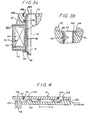
- FIG. 3A and 3B in combination with Figures 1 and 2, it is seen that the entire solenoid assembly 12 is retained assembled by a non-ferrous, flux tube 50 which has a tubular portion 51 with a closed first end 52 and an open second end 54.
- a preferable material for flux tube 50 is copper.
- Adjacent to closed end 52 is a crimp 56 which has a diameter larger than the hole 31 through closed end 33 of the housing 30. Crimp 56 serves as a stop against the closed end 33 of the housing 30 and, as is seen in Figures 1 and 2, provides an internal stop 58 for an armature to be discussed hereinafter.
- the flux tube 50 has a flange 60 which extends radially outward and has a flange face 62 that is held in abutment with the axially facing, radially extending shoulder 48 of the coupling 40.
- the radially extending flange 60 also has an outwardly facing radial surface 64 which is abutted by a fixed core element as will be discussed hereinafter.
- the flux tube 50 initially has an end portion 70 which converges toward the axis 72 of the flux tube.
- This provides an O-ring lead which allows the coupling member 40 with the sealing O-ring 46 therein to be slid over the open-end 54 of the flux tube 50 without cutting or damaging the O-ring 46 so as to clear the end of the flux tube.
- the converging end 70 of the flux tube 50 is deformed to form the flange 60 in order to hold the coupling member 40 in tight engagement with the base plate 32 of the solenoid assembly 12.
- deformation of the converging end 70 is accomplished by a process known as "Taumel Orbital Head Forming" in which a forming tool orbits around the axis 72 of the flux tube 50 so as to deform the open end 52 thereof into the radially extending annular flange 60.
- the flange 60 is formed over many high speed revolutions (for example, over 100 revolutions) of the head the forming tool with all the pressure applied to a line on the flange so that a flowing wave of material forms ahead of the orbiting tool.
- the flange 60 holds the coupling 40 in tight engagement with the shoulder 48 which results in a tight magnetic circuit.
- the flux tube 50 is in effect riveted at open end 54.
- the flux tube 50 acts three capacities, i.e., an O-ring lead for O-ring 46, a flux break, and a fastener which holds the components of the solenoid assembly 12 tightly together.
- an armature 73 which abuts the internal stop 58 formed by the crimp 56 in flux tube with a free-end 74.
- the armature 73 has a frustoconical end 75 with a frustoconical surface 76.
- Projecting from the frustoconical end 75 is a rod 78 of nonmagnetic material which pushes axially against a spool within the valve spool assembly 14, as will be further explained hereinafter.
- the rod 78 passes through a bore 80 in a fixed pole piece 82.
- Fixed core 82 has a first end 84 with a single frustoconical recess 86 that receives and compliments the frustoconical end 75 of the armature 73.
- the coil When the coil is deenergized, there in a gap 87 between the frustoconical recess 86 and the frustoconical end 75 of the armature 73.
- the flux tube 50 By employing the flux tube 50 of non-magnetizable material, short circuitry of flux around the working gap 87 is prevent and the round robin effect normally associated with stacked magnetic components is avoided, resulting in substantially all of the magnetic force being applied in the working gap.
- a second end 85 of the fixed core 82 has a peripheral flange 86 which is in abutment with the radially extending flange 62 (see also Figure 3b) of the flux tube 50.
- valve spool assembly 14 comprises a valve spool 90 having a first end 92 that is abutted by the rod 78 attached to the armature 70 and a second end 94 which abuts a coil spring 96 that is held in place by an annular insert 98.
- a bushing 99 is disposed between the first end 92 of the valve spool 90 and the valve stem 78 to prevent the valve stem from sticking to the fixed pole piece 82 of the solenoid 12.
- the valve spool 90 has a first relieved portion defining an axially extending annular space 100 and a second relieved portion defining an annular space 102 located proximate the second end 94 of the valve spool.
- a hollow core 104 which opens through the valve spool 90 via a port 106 that is in communication with the third relieved space 103, for fluid displacement behind the valve spool, as the valve spool moves away from the pole 82.
- the cylindrical spool housing 110 has four radial tank ports 120 (two of which are shown) which communicate with the internal annular space 100 around the spool 90 and four radial work ports 122 (two of which are shown), which also communicate with annular space 100.
- An axially opening work port 126 is also provided that communicates with the second annular space 102.
- Four radial pump ports 124 also communicate with the second annular space 102 around the end 94 of the valve spool 90.
- the work port 126 is in communication with the bore 104 which in turn is in communication with the third space 103 that is connected to the bore 104 by the port 106. Projecting annular lands 128 and 130 center the valve spool 90 within the valve spool housing 110 and due to their geometry provide a negative lap lag.
- the pump ports 124 When the coil 20 of the solenoid assembly 12 is deenergized, the pump ports 124 connect with the work ports 126, while the work ports 122 connect to the tank ports 120. When the coil 20 of the solenoid assembly 12 is energized, the pump ports 124 disconnect from the work ports 126 and connect to work ports 122, while the tank ports 120 are blocked from all other ports.
- valve spool assembly 16 has essentially the same elements as the two position four-way spool with the exception that in the embodiment of Figure 2, only the pressure ports 124' are present with the axial end port 126' being the tank port. Since there are no tank ports 120 and no radial work ports 122, there are no overlap problems.
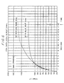
- the linearizing magnetic washer 34 cooperates with the one piece, riveted flux tube 50 to create a more linear magnet force verses displacement curve which parallels the force exerted by the low-rate spring 96.
- spring force 150, hysterisus of friction 152 and magnetic force 154 are plotted as a function of travel for an SAE-6 valve configured in accordance with the present invention. As is readily apparent, the spring force 150, hysterisus due to friction force 152, and magnetic force 154 are substantially parallel.
- the solenoid valve assembly 10 configured in accordance with the arrangement described herein, saturates earlier in the gap 87 and is a hedge against the temperature effect which lowers force as temperature increases.
- the difficulty encountered in designing an SAE-6 solenoid valve assembly is that the armature is about 8mm (0.312") in diameter and thus is too small to readily accommodate the lines of magnetic flux which are spaced a distance apart.
- the force exerted by the solenoid valve shown in Figure 5 is achievable with a coil having 1550 amp turns at 18 watts power, even with an 8mm (0.312") armature.
Landscapes
- Physics & Mathematics (AREA)
- Electromagnetism (AREA)
- Engineering & Computer Science (AREA)
- Power Engineering (AREA)
- Magnetically Actuated Valves (AREA)
Description
- The present invention relates to a coil assembly useful in solenoid valves, and more particularly, the present invention relates to a coil assembly useful in miniature solenoid valves.
- Currently, there are no SAE (Society of Automotive Engineers) 6-sized solenoid valves on the market which operate effectively at elevated temperatures above about 121°C (250° Farenheit) and which exert over 2.7 kilograms (6 pounds) of force. In the past, it has proved difficult to assemble such solenoids in a way that maintains high efficiency at low current as well as providing a linearized force-stroke curve for increased force at the hydraulic switching point. Moreover, it has been difficult to provide efficient hydraulic switching in very small solenoid valves because the valves tend to stick at the switching point. In order to overcome sticking, the tendency has to been to use more powerful larger valve components which, of course, increases the expense and size of the valves. It is now highly desirable to have replaceable electromechanical assemblies in the automotive industry so that an entire assembly is replaced when a component thereof malfunctions. This is in large part because it is very difficult to determine which miniature component is malfunctioning. Accordingly, there is the need for high reliability in components such as miniature valves and it is important that this high reliability be achieved at a low cost. If the valves are relatively expensive, then the cost of replacement electromechanical assemblies is increased and if the valves are unreliable, then a malfunction in a single valve can result in an entire assembly having to be replaced.
- US 4805870 and EP 0762442 each disclose a solenoid valve including a coil accommodated in a housing, and a flux tube which extends beyond axial end walls of the housing, one end of the flux tube being open and having an outturned flange by which the flux tube is retained in the assembled solenoid valve.
- In the solenoid valve of US 4805870, the flange is held between a valve body and a collar whereas in the solenoid valve of EP 0762442 the flange is held between the valve body and a flux washer.
- A source of both expense and unreliability is the retention of the flux tube in the assembly. Other than showing a flange at the open end of the flux tube, US 4805870 and EP 762442 do not address how the flange is formed against other structure.
- As is clear from patents such as U.S. Patent 4,552,179, assembly of miniature solenoid valves has presented a challenge for many years. Cost effective assembly techniques which accomplish more than one function such as minimizing flux leakage and providing a linearized stroke curve which can be matched to a return spring curve are not available.
- In view of the aforementioned considerations, it is a feature of the present invention to provide low cost miniature valves which are efficient and reliable.
- According to the present invention there is provided a solenoid assembly including a coil defining a hollow core and having a first end and a second end; a housing surrounding the coil wherein the housing has an axially extending wall positioned around the coil, a first annular end wall over the first end of the coil and a second annular end wall over the second end of the coil; a flux tube of non-magnetic material extending though the coil and having first and second ends extending respectively through the first and second annular end walls of the housing; a coupling disposed against the second annular end wall of the housing and receiving the second end of the flux tube therethrough, the coupling including a first radial surface abutting the second annular end wall of the housing and a second radial surface facing away from the housing; the solenoid assembly being characterized in that a radial flange projects laterally from the second end of the flux tube, the radial flange having been riveted into engagement with the second radial surface of the coupling to hold the coupling against the second end wall of the housing.
- In a further aspect of the coil assembly, the outwardly extending flange of the flux tube is unitary therewith and formed by a series of orbital impacts.
- In still a further aspect the coil assembly includes a washer of magnetic material disposed in the housing adjacent one end of the flux tube.
- In still a further aspect of the coil assembly the coupling has an internal groove therein in which a seal is seated, the end of the flux tube having been deformed from a diameter less than the tube so that the seal slips readily thereover during assembly.
- In a preferred embodiment in accordance with the present invention, the flux tube has a radially extending portion at its first end, which radially extending portion has a diameter greater than that of the opening through the first end of the housing. An armature is mounted within the flux tube for axial movement therein, and a pole piece is fixed within the flux tube for exerting a magnetic force on the armature to move the armature in a first direction against the bias of a spring.
- In a further aspect, the solenoid assembly includes a washer of magnetic material disposed between the coil and the first end of the housing, the washer having sufficient mass to linearize the magnetic force so as to parallel the spring force over the stroke of the armature.
- In a further aspect, the solenoid assembly includes a spring which acts on the armature applying a spring force in a second direction opposite the first direction.
- In still another aspect of the solenoid assembly a valve spool assembly is included wherein the valve spool assembly has a housing coupled to the coupling and a valve spool within the housing actuated by the armature. The housing includes a plurality of radially opening ports and the spool includes a plurality of lands for opening and closing the ports, the lands opening one port before opening another port.
- In still another aspect of the solenoid assembly one port is a port connected to a pressure pump. Another other port is an exhaust port connected to tank and other ports are work ports.
- According to another aspect of the present invention there is provided a method of fabricating a solenoid assembly including a coil defining a hollow core and having a first end and a second end; a housing surrounding the coil wherein the housing has an axially extending wall positioned around the coil, a first annular end wall over the first end of the coil and a second annular end wall over the second end of the coil; a flux tube of non-magnetic material extending though the coil and having first and second ends extending respectively through the first and second annular end walls of the housing; a coupling disposed against the second annular end wall of the housing and receiving the second end of the flux tube therethrough, the coupling including a first radial surface abutting the housing and a second radial surface facing away from the housing; the method being characterized in that a radial flange projects laterally from the second end of the flux tube is formed by being riveted into engagement with the second radial surface of the coupling to hold the coupling against the second end wall of the housing.
- Various other features and attendant advantages of the present invention will be more fully appreciated as the same becomes better understood when considered in conjunction with the accompanying drawings, in which like reference characters designate the same or similar parts throughout the several views, and wherein:
- Figure 1 is an enlarged side elevation of a miniature solenoid valve configured in accordance with the principles of the present invention showing a two position, four-way valve;
- Figure 2 is a view similar to Figure 1 but illustrating a two position, two-way miniature solenoid valve;
- Figure 3a is an enlarged side view illustrating an assembly principle of the present invention facilitating installation of an O-ring;
- Figure 3b is an enlarged side view illustrating another assembly principle of the present invention wherein components of the invention are riveted together;
- Figure 4 is a side elevation of a proportion of a sleeve and spool assembly with the miniature solenoid valve of Figures 1 and 2;
- Figure 5 is a graph illustrating solenoid force, spring force and hysterisus as a function of armature travel; and
- Figure 6 is a graph illustrating heat dissipation as a function of time with a heat sink and with no heat sink.
-
- Referring now to Figures 1 and 2, a two position four-way, normally open,
miniature valve 10 and a two position two-way, normally open, miniature valve 10' are shown, wherein each valve has anidentical solenoid assembly 12 butdifferent spool assemblies sleeve 18 on both of thesolenoid assemblies 12. While four-way and two-way valve spool assemblies 14 and 16 are shown, the valve assembly may also be a three-way valve assembly or an amplified poppet two-way valve assembly. By so configuring thesolenoid assemblies 12, it is possible to use thesame solenoid assembly 12 for all normally open or normally closed valve logics. - Referring now mainly to Figure 1, the Figure 1
solenoid assembly 12 is comprised of acoil 20 wound around a plastic bobbin 24 having ahollow core 26.Coil 20 and bobbin 24 form a moldedcoil assembly 28 which is mounted in anon-magnetizable steel housing 30 having a round hole 31 through a first closedend 33 and a base plate formed by asecond end wall 32. Disposed directly above themolded coil assembly 28 is a linearizingflux washer 34. - A
coupling 40 abuts theoutside surface 36 of thebase plate 32, thecoupling 40 having the internally threadedsleeve 18 unitary therewith for attaching thereto thevalve spool assemblies coupling 40 includes ahex nut portion 42 having internally openingannular groove 44 which receives an O-ring 46. Thecoupling 40 also includes a radially extending, axially facinginterior shoulder 48 inboard of ahelical thread 49. - Referring now to Figures 3A and 3B in combination with Figures 1 and 2, it is seen that the
entire solenoid assembly 12 is retained assembled by a non-ferrous,flux tube 50 which has atubular portion 51 with a closedfirst end 52 and an opensecond end 54. A preferable material forflux tube 50 is copper. Adjacent to closedend 52 is acrimp 56 which has a diameter larger than the hole 31 through closedend 33 of thehousing 30. Crimp 56 serves as a stop against the closedend 33 of thehousing 30 and, as is seen in Figures 1 and 2, provides aninternal stop 58 for an armature to be discussed hereinafter. At itsopen end 54 theflux tube 50 has aflange 60 which extends radially outward and has aflange face 62 that is held in abutment with the axially facing, radially extendingshoulder 48 of thecoupling 40. The radially extendingflange 60 also has an outwardly facingradial surface 64 which is abutted by a fixed core element as will be discussed hereinafter. - Referring now more specifically to Figure 3a, it is seen that the
flux tube 50 initially has anend portion 70 which converges toward theaxis 72 of the flux tube. This provides an O-ring lead which allows thecoupling member 40 with the sealing O-ring 46 therein to be slid over the open-end 54 of theflux tube 50 without cutting or damaging the O-ring 46 so as to clear the end of the flux tube. When thecoupling 40 rests against thebase 32, the convergingend 70 of theflux tube 50 is deformed to form theflange 60 in order to hold thecoupling member 40 in tight engagement with thebase plate 32 of thesolenoid assembly 12. - In accordance with the present invention, deformation of the converging
end 70 is accomplished by a process known as "Taumel Orbital Head Forming" in which a forming tool orbits around theaxis 72 of theflux tube 50 so as to deform theopen end 52 thereof into the radially extendingannular flange 60. While using the Taumel orbiting machine, theflange 60 is formed over many high speed revolutions (for example, over 100 revolutions) of the head the forming tool with all the pressure applied to a line on the flange so that a flowing wave of material forms ahead of the orbiting tool. This results in aflange 60 of maximum strength with no measurable change in metallurgical structure from thetubular portion 51 structure. Theflange 60 holds thecoupling 40 in tight engagement with theshoulder 48 which results in a tight magnetic circuit. Theflux tube 50 is in effect riveted atopen end 54. - By utilizing many low force, peening strikes rather than conventional riveting with a few high-force strikes, the magnetic reluctance path in the
flux tube 50 is made very tight. Theflux tube 50 therefore acts three capacities, i.e., an O-ring lead for O-ring 46, a flux break, and a fastener which holds the components of thesolenoid assembly 12 tightly together. - Referring again mainly to Figure 1, within the
flux tube 50, there is disposed anarmature 73 which abuts theinternal stop 58 formed by thecrimp 56 in flux tube with a free-end 74. Thearmature 73 has afrustoconical end 75 with a frustoconical surface 76. Projecting from thefrustoconical end 75 is arod 78 of nonmagnetic material which pushes axially against a spool within thevalve spool assembly 14, as will be further explained hereinafter. Therod 78 passes through abore 80 in a fixedpole piece 82. Fixedcore 82 has a first end 84 with asingle frustoconical recess 86 that receives and compliments thefrustoconical end 75 of thearmature 73. When the coil is deenergized, there in a gap 87 between thefrustoconical recess 86 and thefrustoconical end 75 of thearmature 73. By employing theflux tube 50 of non-magnetizable material, short circuitry of flux around the working gap 87 is prevent and the round robin effect normally associated with stacked magnetic components is avoided, resulting in substantially all of the magnetic force being applied in the working gap. Asecond end 85 of the fixedcore 82 has aperipheral flange 86 which is in abutment with the radially extending flange 62 (see also Figure 3b) of theflux tube 50. - Thus far, the
solenoid assembly 12 has been described as used interchangeably with valve spools such as the valve spools 14 and 16 of Figures 1 and 2. The following description is of the two-position, four-way, normally open,valve spool assembly 14 of Figure 1. As is seen in Figure 1, thevalve spool assembly 14 comprises avalve spool 90 having a first end 92 that is abutted by therod 78 attached to thearmature 70 and asecond end 94 which abuts acoil spring 96 that is held in place by anannular insert 98. Abushing 99 is disposed between the first end 92 of thevalve spool 90 and thevalve stem 78 to prevent the valve stem from sticking to the fixedpole piece 82 of thesolenoid 12. Thevalve spool 90 has a first relieved portion defining an axially extendingannular space 100 and a second relieved portion defining anannular space 102 located proximate thesecond end 94 of the valve spool. Within thevalve spool 90, there is ahollow core 104 which opens through thevalve spool 90 via a port 106 that is in communication with the thirdrelieved space 103, for fluid displacement behind the valve spool, as the valve spool moves away from thepole 82. - Surrounding the
spool 90 to form thespool assembly 14 is acylindrical spool housing 110.Cylindrical spool housing 110 has a threadedend 112 which is received in the internally threadedsleeve 18 of thecoupling 40. O-ring seal 114 surrounds a projectingend portion 116 which surrounds thespacer 99. - The
cylindrical spool housing 110 has four radial tank ports 120 (two of which are shown) which communicate with the internalannular space 100 around thespool 90 and four radial work ports 122 (two of which are shown), which also communicate withannular space 100. An axiallyopening work port 126 is also provided that communicates with the secondannular space 102. Fourradial pump ports 124 also communicate with the secondannular space 102 around theend 94 of thevalve spool 90. Thework port 126 is in communication with thebore 104 which in turn is in communication with thethird space 103 that is connected to thebore 104 by the port 106. Projectingannular lands valve spool 90 within thevalve spool housing 110 and due to their geometry provide a negative lap lag. - When the
coil 20 of thesolenoid assembly 12 is deenergized, thepump ports 124 connect with thework ports 126, while thework ports 122 connect to thetank ports 120. When thecoil 20 of thesolenoid assembly 12 is energized, thepump ports 124 disconnect from thework ports 126 and connect to workports 122, while thetank ports 120 are blocked from all other ports. - Referring now to Figure 4, it is seen that when stroking the
solenoid valve 14 that theland 128 which covers thetank ports 120 closes slightly before theland 130 which closes thepump ports 124. This is because the distance between theleading edge 135 ofland 128, and theleading edge 137 of theland 130 is less than the distance between the ends 139 and 141 of the tank and pumpports valve spool 90 is destroked, thepump port 130 opens prior to thetank port 120. This allows less shifting effort when closingtank port 120 before openingpump port 124 and is in concert with force exerted by the coil spring 96 (see Figure 1). InSAE 6 solenoid valves, the negative lap is about 0.12 mm (0.004") with a stroke of about 2.2mm (0.086"). - Referring again to Figure 2, where a two position two-way
valve spool assembly 16 is shown, the valve spool assembly has essentially the same elements as the two position four-way spool with the exception that in the embodiment of Figure 2, only the pressure ports 124' are present with the axial end port 126' being the tank port. Since there are notank ports 120 and noradial work ports 122, there are no overlap problems. - Referring now to Figure 5 in concert with Figures 1 and 2, the linearizing
magnetic washer 34 cooperates with the one piece, rivetedflux tube 50 to create a more linear magnet force verses displacement curve which parallels the force exerted by the low-rate spring 96. In Figure 5,spring force 150, hysterisus of friction 152 and magnetic force 154 are plotted as a function of travel for an SAE-6 valve configured in accordance with the present invention. As is readily apparent, thespring force 150, hysterisus due to friction force 152, and magnetic force 154 are substantially parallel. - The
washer 34 basically acts as a force stroke linearizer and has a small heat sink effect which results from mounting the solenoid assembly in a mounting block or manifold. The effect of moving thearmature 73 andpole 82 to magnetic saturation upon energizing is due to closing the gap between them to the coil amp-turns. The coil amp-turns are designed to cause the circuit to saturate early so that the max force is obtained and the force stroke curve is more linearized by the effect ofthick washer 34. As a consequence, the coil size and current draw within the magnetic gap 87 cause the magnetic circuit to magnetically saturate early in the stroke. The effect is, that as thecoil 20 heats up and electrical resistance increases, the current falls off but not enough to drop out of saturation and diminish the magnetic pull force effect. With this arrangement the solenoid force output does not drop off as fast as it ordinarily would with a rise in temperature. Thesolenoid valve assembly 10, configured in accordance with the arrangement described herein, saturates earlier in the gap 87 and is a hedge against the temperature effect which lowers force as temperature increases. - The difficulty encountered in designing an SAE-6 solenoid valve assembly is that the armature is about 8mm (0.312") in diameter and thus is too small to readily accommodate the lines of magnetic flux which are spaced a distance apart. By configuring the solenoid valve as described in this specification, the force exerted by the solenoid valve shown in Figure 5 is achievable with a coil having 1550 amp turns at 18 watts power, even with an 8mm (0.312") armature.
- In summary, due to highly efficient coil and reluctance path design, a relatively high force output is obtained with a low wattage input for SAE-6 solenoid valves.
Claims (7)
- A solenoid assembly (12) including a coil (20) defining a hollow core (26) and having a first end and a second end; a housing (30) surrounding the coil (20) wherein the housing (30) has an axially extending wall positioned around the coil, a first annular end wall (33) over the first end of the coil (20) and a second annular end wall (32) over the second end of the coil (20); a flux tube (50) of non-magnetic material extending though the coil (20) and having first and second ends (52 and 54) extending respectively through the first and second annular end walls (33, 32) of the housing (30); a coupling (40) disposed against the second annular end wall (32) of the housing (30) and receiving the second end (54) of the flux tube (50) therethrough, the coupling (40) including a first radial surface (40a) abutting the second annular end wall (32) of the housing (30) and a second radial surface (48) facing away from the housing (30); the solenoid assembly (12) being characterized in that a radial flange (60) projects laterally from the second end (54) of the flux tube (50), the radial flange (60) having been riveted into engagement with the second radial surface (48) of the coupling (40) to hold the coupling (40) against the second end wall (32) of the housing (30).
- A solenoid assembly as claimed in claim 1 wherein the radially extending flange (60) at the second end (54) of the flux tube (50) is formed of material initially co-extensive with the flux tube (50) and is riveted against the radial surface (48) of the coupling (40) by a series of orbital impacts.
- A solenoid assembly as claimed in claim 2, wherein the coupling (40) has an internal groove (44) therein in which an annular seal (46) is seated, and wherein the second end (54) of the flux tube (50) has been deformed by said orbital impacts from an initial diameter (70) less than the diameter of flux tube (50) to enable the coupling (40) to readily slide over the second end (54) of the flux tube (50) during assembly without the second end (54) of the flux tube (50) biting into the annular seal (46).
- A method of fabricating a solenoid assembly (12) including a coil (20) defining a hollow core (26) and having a first end and a second end; a housing (30) surrounding the coil (20) wherein the housing (30) has an axially extending wall positioned around the coil, a first annular end wall (33) over the first end of the coil (20) and a second annular end wall (32) over the second end of the coil (20); a flux tube (50) of non-magnetic material extending though the coil (20) and having first and second ends (52 and 54) extending respectively through the first and second annular end walls (33, 32) of the housing (30); a coupling (40) disposed against the second annular end wall (32) of the housing (30) and receiving the second end (54) of the flux tube (50) therethrough, the coupling (40) including a first radial surface (40a) abutting the housing and a second radial surface (48) facing away from the housing (30); the method being characterized in that a radial flange (60) projects laterally from the second end (54) of the flux tube (50) is formed by being riveted into engagement with the second radial surface (48) of the coupling (40) to hold the coupling (40) against the second end wall (32) of the housing (30).
- A method as claimed in claim 4 wherein the radially extending flange (60) at the second end (54) of the flux tube (50) is formed of material initially co-extensive with the flux tube (50) and is riveted against the radial surface (48) of the coupling (40) by a series of orbital impacts.
- A method as claimed in claim 5 wherein the coupling (40) has an internal groove (44) therein in which an annular seal (46) is seated and wherein prior to deforming the second end (54) of the flux tube (50) by said orbital impacts the second end (54) has an initial diameter (70) less than the diameter of the flux tube (50) to enable the coupling (40) to readily slide over the second end (54) of the flux tube (50) during assembly without the second end (54) of the flux tube (50) biting into the annular seal (46).
- A solenoid assembly fabricated by a method in accordance with any one of claims 4 to 6.
Applications Claiming Priority (2)
| Application Number | Priority Date | Filing Date | Title |
|---|---|---|---|
| US09/001,148 US6092784A (en) | 1997-12-30 | 1997-12-30 | Coil assembly useful in solenoid valves |
| US1148 | 1997-12-30 |
Publications (3)
| Publication Number | Publication Date |
|---|---|
| EP0928010A2 EP0928010A2 (en) | 1999-07-07 |
| EP0928010A3 EP0928010A3 (en) | 2000-07-12 |
| EP0928010B1 true EP0928010B1 (en) | 2005-06-15 |
Family
ID=21694625
Family Applications (1)
| Application Number | Title | Priority Date | Filing Date |
|---|---|---|---|
| EP98310684A Expired - Lifetime EP0928010B1 (en) | 1997-12-30 | 1998-12-23 | Coil assembly useful in solenoid valves |
Country Status (3)
| Country | Link |
|---|---|
| US (1) | US6092784A (en) |
| EP (1) | EP0928010B1 (en) |
| DE (1) | DE69830562T2 (en) |
Families Citing this family (20)
| Publication number | Priority date | Publication date | Assignee | Title |
|---|---|---|---|---|
| US6392516B1 (en) * | 1998-12-04 | 2002-05-21 | Tlx Technologies | Latching solenoid with improved pull force |
| US8068897B1 (en) | 1999-03-01 | 2011-11-29 | Gazdzinski Robert F | Endoscopic smart probe and method |
| US7914442B1 (en) | 1999-03-01 | 2011-03-29 | Gazdzinski Robert F | Endoscopic smart probe and method |
| US10973397B2 (en) | 1999-03-01 | 2021-04-13 | West View Research, Llc | Computerized information collection and processing apparatus |
| US8636648B2 (en) | 1999-03-01 | 2014-01-28 | West View Research, Llc | Endoscopic smart probe |
| US6918409B1 (en) * | 2001-12-13 | 2005-07-19 | Honeywell International Inc. | Spool and poppet inlet metering valve |
| DE50205601D1 (en) * | 2002-06-12 | 2006-04-06 | Fsp Fluid Sys Partners Holding | Cartridge |
| US7205685B2 (en) * | 2002-11-14 | 2007-04-17 | Woco Industrietechnik Gmbh | Solenoid plunger system with an adjustable magnetic flux |
| US8297532B2 (en) * | 2008-06-09 | 2012-10-30 | Caterpillar Inc. | Apparatus for cooling a fuel injector |
| US8585014B2 (en) * | 2009-05-13 | 2013-11-19 | Keihin Corporation | Linear solenoid and valve device using the same |
| JP2011077355A (en) * | 2009-09-30 | 2011-04-14 | Keihin Corp | Linear solenoid and valve device using the same |
| US8733732B2 (en) * | 2010-05-24 | 2014-05-27 | Eaton Corporation | Pressurized o-ring pole piece seal for a manifold |
| KR101158423B1 (en) * | 2010-05-26 | 2012-06-22 | 주식회사 케피코 | Hydraulic solenoid valve for auto transmission of car |
| US8733729B2 (en) | 2011-10-10 | 2014-05-27 | Liebert Corporation | Back pressure capable solenoid operated diaphragm pilot valve |
| US9097362B2 (en) * | 2012-02-27 | 2015-08-04 | Parker-Hannifin Corporation | Fast switching hydraulic pilot valve with hydraulic feedback |
| EP2931983B1 (en) * | 2012-12-14 | 2018-09-19 | Eaton Corporation | System and methods for controlled lowering and lifting of a load |
| CN107407435A (en) * | 2015-02-12 | 2017-11-28 | 伊顿公司 | Solenoid with enlarging course |
| JP6421745B2 (en) * | 2015-12-11 | 2018-11-14 | オムロン株式会社 | relay |
| JP6575343B2 (en) | 2015-12-11 | 2019-09-18 | オムロン株式会社 | relay |
| US10726985B2 (en) * | 2018-03-22 | 2020-07-28 | Schaeffler Technologies AG & Co. KG | Multi-stage actuator assembly |
Family Cites Families (17)
| Publication number | Priority date | Publication date | Assignee | Title |
|---|---|---|---|---|
| US3262027A (en) * | 1964-04-06 | 1966-07-19 | Automatic Switch Co | Solenoid structure and mounting means therefor |
| US3593241A (en) * | 1969-07-18 | 1971-07-13 | Alfred J Ludwig | Solenoid valve having a slotted flux sleeve for nesting the winding leads |
| US4442998A (en) * | 1979-07-24 | 1984-04-17 | Aisin Seiki Kabushiki Kaisha | Electromagnetic valve unit |
| JPS6127137Y2 (en) * | 1981-01-08 | 1986-08-13 | ||
| US4805870A (en) * | 1983-02-03 | 1989-02-21 | Emerson Electric Co. | Coil retainer for solenoid |
| EP0139811B1 (en) * | 1983-08-25 | 1989-08-16 | CKD Corporation | Miniature solenoid valve |
| US4638974A (en) * | 1984-01-06 | 1987-01-27 | Zeuner Kenneth W | Electrohydraulic valve assemblies and method |
| JPS61103076A (en) * | 1984-10-25 | 1986-05-21 | Toyoda Mach Works Ltd | Linear solenoid valve |
| US4649360A (en) * | 1986-02-28 | 1987-03-10 | Parker Vannifin Corporation | Solenoid valve with contractible assembly ring |
| US4697608A (en) * | 1986-04-30 | 1987-10-06 | Eaton Corporation | Electromagnetic valve assembly |
| KR930001020B1 (en) * | 1987-06-16 | 1993-02-12 | 스미도모 덴기 고오교오 가부시기가이샤 | Fluid pressure controller |
| US4880205A (en) * | 1987-06-30 | 1989-11-14 | Parker Hannifin Corporation | Hung diaphragm solenoid valve |
| IT1211628B (en) * | 1987-12-24 | 1989-11-03 | Weber Srl | ELECTROMAGNETIC CONTROL VALVE FOR THE CONTROL OF A AIR FLOW RATE IN A FUEL SUPPLY DEVICE FOR INTERNAL COMBUSTION ENGINE |
| JPH02180390A (en) * | 1988-12-30 | 1990-07-13 | Aisin Aw Co Ltd | Pressure control valve |
| US5002253A (en) * | 1989-10-30 | 1991-03-26 | Sterling Hydraulics, Inc. | Solenoid valve |
| JP2898081B2 (en) * | 1990-11-05 | 1999-05-31 | アイシン・エィ・ダブリュ株式会社 | Linear solenoid valve and method of assembling the same |
| CA2147156C (en) * | 1992-10-15 | 1999-12-21 | Chester D. Campbell | Valve for air conditioning system with proportional solenoid |
-
1997
- 1997-12-30 US US09/001,148 patent/US6092784A/en not_active Expired - Lifetime
-
1998
- 1998-12-23 DE DE69830562T patent/DE69830562T2/en not_active Expired - Lifetime
- 1998-12-23 EP EP98310684A patent/EP0928010B1/en not_active Expired - Lifetime
Also Published As
| Publication number | Publication date |
|---|---|
| EP0928010A3 (en) | 2000-07-12 |
| EP0928010A2 (en) | 1999-07-07 |
| US6092784A (en) | 2000-07-25 |
| DE69830562T2 (en) | 2006-05-11 |
| DE69830562D1 (en) | 2005-07-21 |
Similar Documents
| Publication | Publication Date | Title |
|---|---|---|
| EP0928010B1 (en) | Coil assembly useful in solenoid valves | |
| JP4285354B2 (en) | Linear solenoid and solenoid valve | |
| US8109487B2 (en) | Linear solenoid device and electromagnetic valve | |
| US6619616B1 (en) | Solenoid valve device | |
| US6542059B2 (en) | Solenoid for electromagnetic valve | |
| US20060065315A1 (en) | Directly operated pneumatic valve having a differential assist return | |
| EP1617116B1 (en) | Solenoid-operated valve | |
| JP2002188749A (en) | Solenoid valve | |
| US20210278007A1 (en) | Solenoid | |
| EP0222223B1 (en) | Inline solenoid operated slide valve | |
| US20080230452A1 (en) | Spool valve | |
| US4763091A (en) | Air gap setting device for electromagnets | |
| US7992839B2 (en) | Electrohydraulic valve having a solenoid actuator plunger with an armature and a bushing | |
| US8141842B2 (en) | Solenoid valve | |
| US6701959B1 (en) | High flow rate balanced poppet valve | |
| US6792975B2 (en) | Pulse-width modulated solenoid valve including axial stop spool valve | |
| JP2020088143A (en) | solenoid | |
| JPH11264403A (en) | Unified electric hydraulic actuator | |
| JP4214964B2 (en) | solenoid valve | |
| JP4372448B2 (en) | Proportional solenoid valve | |
| WO2019026211A1 (en) | Electromagnetic type drive unit | |
| EP1284384B1 (en) | Solenoid for solenoid valve | |
| JP2004316855A (en) | Proportional solenoid valve | |
| US4694270A (en) | Electromagnetic proportional actuator | |
| US20070075283A1 (en) | Valve apparatus |
Legal Events
| Date | Code | Title | Description |
|---|---|---|---|
| PUAI | Public reference made under article 153(3) epc to a published international application that has entered the european phase |
Free format text: ORIGINAL CODE: 0009012 |
|
| AK | Designated contracting states |
Kind code of ref document: A2 Designated state(s): BE DE IT SE |
|
| AX | Request for extension of the european patent |
Free format text: AL;LT;LV;MK;RO;SI |
|
| PUAL | Search report despatched |
Free format text: ORIGINAL CODE: 0009013 |
|
| AK | Designated contracting states |
Kind code of ref document: A3 Designated state(s): AT BE CH CY DE DK ES FI FR GB GR IE IT LI LU MC NL PT SE |
|
| AX | Request for extension of the european patent |
Free format text: AL;LT;LV;MK;RO;SI |
|
| RIC1 | Information provided on ipc code assigned before grant |
Free format text: 7H 01F 7/06 A, 7H 01F 7/16 B, 7F 16K 31/06 B |
|
| RAP1 | Party data changed (applicant data changed or rights of an application transferred) |
Owner name: PARKER HANNIFIN CORPORATION |
|
| 17P | Request for examination filed |
Effective date: 20010108 |
|
| AKX | Designation fees paid |
Free format text: BE DE IT SE |
|
| 17Q | First examination report despatched |
Effective date: 20040112 |
|
| GRAP | Despatch of communication of intention to grant a patent |
Free format text: ORIGINAL CODE: EPIDOSNIGR1 |
|
| GRAS | Grant fee paid |
Free format text: ORIGINAL CODE: EPIDOSNIGR3 |
|
| GRAA | (expected) grant |
Free format text: ORIGINAL CODE: 0009210 |
|
| AK | Designated contracting states |
Kind code of ref document: B1 Designated state(s): BE DE IT SE |
|
| REF | Corresponds to: |
Ref document number: 69830562 Country of ref document: DE Date of ref document: 20050721 Kind code of ref document: P |
|
| REG | Reference to a national code |
Ref country code: SE Ref legal event code: TRGR |
|
| PLBE | No opposition filed within time limit |
Free format text: ORIGINAL CODE: 0009261 |
|
| STAA | Information on the status of an ep patent application or granted ep patent |
Free format text: STATUS: NO OPPOSITION FILED WITHIN TIME LIMIT |
|
| 26N | No opposition filed |
Effective date: 20060316 |
|
| PGFP | Annual fee paid to national office [announced via postgrant information from national office to epo] |
Ref country code: BE Payment date: 20090126 Year of fee payment: 11 |
|
| BERE | Be: lapsed |
Owner name: *PARKER HANNIFIN CORP. Effective date: 20091231 |
|
| PG25 | Lapsed in a contracting state [announced via postgrant information from national office to epo] |
Ref country code: BE Free format text: LAPSE BECAUSE OF NON-PAYMENT OF DUE FEES Effective date: 20091231 |
|
| PGFP | Annual fee paid to national office [announced via postgrant information from national office to epo] |
Ref country code: IT Payment date: 20141227 Year of fee payment: 17 Ref country code: DE Payment date: 20141230 Year of fee payment: 17 |
|
| PGFP | Annual fee paid to national office [announced via postgrant information from national office to epo] |
Ref country code: SE Payment date: 20150102 Year of fee payment: 17 |
|
| REG | Reference to a national code |
Ref country code: DE Ref legal event code: R119 Ref document number: 69830562 Country of ref document: DE |
|
| REG | Reference to a national code |
Ref country code: SE Ref legal event code: EUG |
|
| PG25 | Lapsed in a contracting state [announced via postgrant information from national office to epo] |
Ref country code: SE Free format text: LAPSE BECAUSE OF NON-PAYMENT OF DUE FEES Effective date: 20151224 |
|
| REG | Reference to a national code |
Ref country code: DE Ref legal event code: R082 Ref document number: 69830562 Country of ref document: DE Representative=s name: HASELTINE LAKE KEMPNER LLP, DE Ref country code: DE Ref legal event code: R082 Ref document number: 69830562 Country of ref document: DE Representative=s name: HASELTINE LAKE LLP, DE |
|
| PG25 | Lapsed in a contracting state [announced via postgrant information from national office to epo] |
Ref country code: DE Free format text: LAPSE BECAUSE OF NON-PAYMENT OF DUE FEES Effective date: 20160701 |
|
| PG25 | Lapsed in a contracting state [announced via postgrant information from national office to epo] |
Ref country code: IT Free format text: LAPSE BECAUSE OF NON-PAYMENT OF DUE FEES Effective date: 20151223 |