EP0927693A1 - In-line processing of flat object - Google Patents
In-line processing of flat object Download PDFInfo
- Publication number
- EP0927693A1 EP0927693A1 EP98204490A EP98204490A EP0927693A1 EP 0927693 A1 EP0927693 A1 EP 0927693A1 EP 98204490 A EP98204490 A EP 98204490A EP 98204490 A EP98204490 A EP 98204490A EP 0927693 A1 EP0927693 A1 EP 0927693A1
- Authority
- EP
- European Patent Office
- Prior art keywords
- transport
- objects
- specimens
- sheets
- buffer
- Prior art date
- Legal status (The legal status is an assumption and is not a legal conclusion. Google has not performed a legal analysis and makes no representation as to the accuracy of the status listed.)
- Granted
Links
Images



Classifications
-
- B—PERFORMING OPERATIONS; TRANSPORTING
- B65—CONVEYING; PACKING; STORING; HANDLING THIN OR FILAMENTARY MATERIAL
- B65H—HANDLING THIN OR FILAMENTARY MATERIAL, e.g. SHEETS, WEBS, CABLES
- B65H83/00—Combinations of piling and depiling operations, e.g. performed simultaneously, of interest apart from the single operation of piling or depiling as such
- B65H83/02—Combinations of piling and depiling operations, e.g. performed simultaneously, of interest apart from the single operation of piling or depiling as such performed on the same pile or stack
-
- B—PERFORMING OPERATIONS; TRANSPORTING
- B65—CONVEYING; PACKING; STORING; HANDLING THIN OR FILAMENTARY MATERIAL
- B65H—HANDLING THIN OR FILAMENTARY MATERIAL, e.g. SHEETS, WEBS, CABLES
- B65H29/00—Delivering or advancing articles from machines; Advancing articles to or into piles
- B65H29/66—Advancing articles in overlapping streams
-
- B—PERFORMING OPERATIONS; TRANSPORTING
- B65—CONVEYING; PACKING; STORING; HANDLING THIN OR FILAMENTARY MATERIAL
- B65H—HANDLING THIN OR FILAMENTARY MATERIAL, e.g. SHEETS, WEBS, CABLES
- B65H7/00—Controlling article feeding, separating, pile-advancing, or associated apparatus, to take account of incorrect feeding, absence of articles, or presence of faulty articles
- B65H7/20—Controlling associated apparatus
Definitions
- This invention relates to a method for in-line processing flat objects according to the introductory portion of claim 1 and to a system for in-line processing flat objects according to the introductory portion of claim 12.
- a drawback of this device is that collecting printed documents into a stack and separating documents again requires relatively costly and sensitive equipment and in itself also constitutes a source of malfunctions.
- the upstream device sometimes dispenses objects that cannot be directly processed by the downstream finishing system because the latter is at a standstill or is processing supplied objects with a frequency which is at least temporarily lower than the frequency with which these are dispensed by the upstream device.
- the object of the invention is to provide a possibility for temporarily buffering flat objects between a device that dispenses the objects and downstream transport facilities, allowing the flat objects, with simple facilities, to be reliably stored and subsequently dispensed serially.
- the flat objects are temporarily stored at a pitch smaller than the size of those objects in the direction of transport, a large number of specimens of the flat objects can be collected in a buffer portion of a small length, but because the specimens are stored with a pitch in the direction of transport, they can easily be moved away from each other again.
- Examples of flat objects that can be advantageously processed with the method and the system according to the invention are: sheets of paper or other material, such as plastic, cards, envelopes which may or may not be filled, quires, and booklets.
- a particular advantage of the invention is that it further makes it possible to temporarily store in a compact manner flat objects in turn consisting of a plurality of stacked sheets or the like, which may or may not be bonded together, and subsequently to move these away from each other again for further processing. Because the objects are stored so as to be staggered relative to each other in the direction of transport, they can be simply treated separately again without sheets of a stack being moved away from each other.
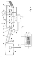
- FIG. 1 shows an example of a situation in which the invention can be employed with particular advantage.
- a computer system 1 includes data regarding the contents of documents, for instance in the form of a set of files 2 (optionally in conjunction with mail merge files) generated with a word processing or DTP system, and a set of finishing data 3 each associated with a file.
- a printer 4 of a generally commercially available type (what printer is chosen may conventionally depend on the requirements imposed regarding the printing possibilities and the capacity of the printer) and a finishing system.
- the finishing system in this example is an inserter system 5 which is made up of a buffer station 6, a collecting station 7, an insert feeder station 8, a folding station 9 and an inserter station 10.
- finishing systems such as binding systems or packaging systems
- finishing systems may also be arranged downstream of the printer.
- a different device that dispenses documents such as a reading device, a copying device, or a plastifying device, can be used.
- the finishing system is provided with a control unit 11 which communicates with the computer 1 via a connection 12.
- the computer 1 is further coupled with a control unit 14 of the printer 4 via a connection 13.
- the printer 4, the collecting station 7, the insert feeder station 8, the folding station 9 and the inserter station 10 can be of a commercially available type. Printers and suitable finishing stations are commercially available from various providers. These parts are therefore not described in further detail here.
- the buffer station 6 has an entrance 15, whose height is adjustable to the height of the exit of the printer 4 in that the buffer station 6 is pivotally mounted adjacent its exit 16, and in that it is provided, remote from and upstream of the pivot 17, with a height-adjustable support 18.
- the data regarding the contents of documents are converted into printing instructions in accordance with the requirements valid for the printer 4 in question. These printing instructions are then transmitted to the printer, where documents are printed in accordance with those printing instructions. Also, the associated data regarding the desired finish of the documents are converted into finishing instructions in accordance with the requirements dictated by the finishing system in question, which finishing instructions are transmitted to the control unit 11.
- the control unit 11 and the stations 7-10 controlled thereby are arranged for carrying out finishing instructions according as documents arrive from the printer 4 in the stations 7-10 in question.
- the stations 7-10 are provided with path monitoring sensors 19-22, which are connected to control modules 24-27 of the corresponding stations 7-10.
- These control modules are connected to the control unit 11, but may also be connected to each other, for instance for the direct upstream transmission of 'ready' reports.
- the documents or interposed control documents may be provided with marks to ensure that each document is subjected to the correct finishing operations. It is also possible to determine the finishing instructions in their entirety by reading marks on the documents, so that communication between the computer 1 and the control unit 11 of the inserter system 5 can be dispensed with entirely.
- the inserter system 5 and the buffer station 6 form a system for the in-line processing of flat objects, in this case sheets, received one by one from the upstream printer 4.
- the buffer station 6 forms a buffer portion located upstream of the path monitors 19-22.
- the buffer station 6 too is provided with a control module 29, which is arranged for controlling different drives of the buffer station 6.
- the control modules 24-27, 29 and the control unit 11 form a control structure which is operatively connected to the transport path 28 for controlling the transport path 28.
- This control structure and the buffer portion 6 are arranged for controlling the buffer portion of the transport path 28 such that flat objects are collected in the buffer station 6 in a configuration with a pitch in the direction of transport that is shorter than the dimensions of the corresponding flat objects in the direction of transport. Further, the buffer station is so arranged that, from that configuration, in the order in which the collected flat objects have been collected, the collected flat objects are moved away from each other and are further transported with mutual interspaces.
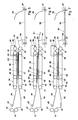
- FIG. 2-7 An example of the buffer station 6 will now be described with reference to Figs. 2-7, representing different operating stages of a buffer station 6 and an adjacent, upstream portion of an inserter system 5.
- the buffer portion of the transport path 28 is formed by two pairs of engagement surfaces 30, 31 and 32, 33, located opposite each other on opposite sides of the transport path 28.
- a gap is drawn between the surfaces 30, 31 and 32, 33 on opposite side of the transport path 28, but in practice opposite surfaces in the proposed example form a transport nip which is closed when no sheets or the like are disposed therebetween.
- transport nips are located between transport rollers 36, 37, whose external surfaces form two of the engagement surfaces 32, 33, and between transport belts 34, 35, whose circumferential surfaces form two others of the engagement surfaces 30, 31, and are spaced apart in the direction of transport.
- rollers 38, 39 over which the transport belts 34, 35 pass, as well as the transport rollers 36, 37, are connected to a drive structure 40 for rotating those rollers 36-39 and thus moving the engagement surfaces 30-33.
- the design of such drives is generally known in this technical field and is therefore not further shown or described.
- the drive structure 40 is arranged for moving the surfaces 32, 33, which delimit a downstream one of the transport nips (between the rollers 36, 37) at a particular speed in the direction of transport, and for blocking, or moving at a lower, second speed in the direction of transport, the engagement surfaces 30, 31, which delimit a more upstream one of the transport nips discussed.
- the entrance 15 of the buffer station is formed by a pair of feed-in rollers 41, 42. Further, just downstream of the feed-in rollers 41, 42, a sensor 43 is located for detecting the arrival of documents. Further located between the feed-in rollers 41, 42 and the transport belts 34, 35 are upper and lower paper guides 44, 45. The transport belts 34, 35, opposite the driven, downstream return rollers 38, 39, pass over upstream return rollers 46, 47. Located between the upstream return rollers 46, 47 and the downstream return rollers 38, 39 are pressure rollers 48, 49, whose positions in the direction of transport are adjustable as indicated by arrows 50, 51, 52, 53 (only in Fig. 2).
- Located downstream of the buffer station 6 are paper guides 54, 55, which are located above a transport surface 56. Extending through slots (not visible in the drawing) in the transport surface 56 are transport fingers 57 which are movable in the direction of transport for passing sheets along the stations 7 and 8.
- sheets dispensed by the printer are first received between the feed-in rollers 41, 42 and then, as soon as the leading edge has reached a position adjacent the sensor 43, detected.
- the sheets are dispensed by the printer and received between the feed-in rollers 41, 42.
- the pitch between successive specimens of the sheets is always greater than or equal to the dimensions of the sheets in question in the direction of transport, so that the sheets do not overlap.
- the inserter system 5 works with a shorter stroke time than does the printer 4
- the sheets are transported by the buffer station to a delivery position and dispensed as soon as the collecting station 7 has issued a 'ready' signal.
- at least a first specimen of the sheets is transported over at least some distance into the system.
- the stroke time of the printer is temporarily shorter than that of the inserter system. In that case, sheets following the at least one leading specimen of the sheets are temporarily collected in the buffer station 6.
- the printer proceeds, with some delay, to cease dispensing sheets.
- sheets in a printer (as a laser printer) are printed in accordance with sets of printing instructions each defining a printing of a page.
- the printer is controlled for stopping the printing, at least one set of printing instructions being processed must be processed before the printing of specimens of the objects is stopped, because otherwise the printing process is disturbed, which would lead, for instance, to traces on the printed sheets.
- sheets can be collected and temporarily stored in a buffer stock between the printer 4 and the finishing system arranged in line therewith.
- the temporary collection of the sheets occurs in a configuration with a pitch in the direction of transport, which is less than the dimensions in the direction of transport of the specimens of the sheets in question. This is represented in Fig. 2-4.
- the inserter system 5 When the inserter system 5 operates faster again than the printer 4, for instance in that the malfunction has been removed or in that the printer is temporarily not provided with printing instructions, the collected sheets are subsequently moved away from each other from that configuration, in the order in which they have been collected, and transported further with mutual interspaces over the transport surface 56. This is represented in Figs. 5-7.
- Storing sheets or sets of sheets which are to be temporarily kept in a buffer stock, in a configuration staggered in the direction of transport but with a shortened pitch in the direction of transport, offers the advantage that on the one hand the buffer stock occupies little space in the direction of transport and that, on the other hand, the collected sheets or set of sheets, on the basis of their positions in the direction of transport, can easily be moved away from each other again when they are to be processed further. In particular, no separation system is needed, as is the case for separating sheets stored in a stack. Further, sheets belonging to each other can be discharged away from other sheets, even if they are not bonded together or do not exhibit any other mechanical form of coherence.
- the sheets are brought into a configuration where they overlap each other like roof-tiles, by moving the transport belts 34, 35 each time when a sheet reaches those belts, over just a distance that is less than the length of each of the sheets in the direction of transport.
- this is shown for three sheets S 1 , S 2 , and S 3 . All this, as appears from the drawing, can be realized with a simple transport structure and the overlapping storage makes it possible to store a very great number of sheets without necessitating complex facilities for retaining the separate sheets or sets of sheets.
- the leading sheet S1 is carried into a delivery position, as is represented in Fig. 5.
- the transport rollers 36, 37 which form the downstream nip of the buffer station 6, are subsequently driven for dispensing the sheet S 1 , as is represented in Fig. 6.
- the sheet S 1 is clear of the transport rollers 36, 37, the next sheet S 2 is carried into the delivery position between the transport rollers.
- the sheets can easily be moved away from each other again in that it is simple to accomplish that the downstream nip between the surfaces 32, 33 of the rollers 36, 37 engages exclusively a sheet or set of sheets to be dispensed.
- a particularly reliable delivery of the sheets can be accomplished by holding the sheets at a distance L2 (see Fig. 2), which is greater than the length of the portion of a sheet or set of sheets to be dispensed, upstream of the nip between the surfaces 32, 33 of the rollers 36, 37, in a nip with a high normal force. This reliably prevents sheets from being carried along when preceding sheets are being dispensed. Those preceding sheets have already left the area of that nip, so that only those sheets are not retained by the normal force in that nip.
- the nip for holding the sheets not yet to be dispensed is formed by the pair of rollers 48, 49 between the return rollers 38, 39, 46, 47 of the transport belts. Because the distance in the direction of transport between the transport nips between, on the one hand, the rollers 36, 37 and, on the other hand, the rollers 48, 49 is adjustable, that distance can be adapted to the length of the documents to be processed.
- nip can be activated for retaining sheets that is located at a distance from the transport rollers 36, 37 that corresponds with (is preferably just greater than) the length in the direction of transport of the sheets or sets of sheets to be processed.
- the downstream return rollers 38, 39 of the transport belts 34, 35 form a third transport nip which is located in the direction of transport between the two transport nips between the roller pairs 36, 37 and 48, 49.
- This third transport nip is arranged for exerting less pressure and hence less traction on an object in that nip than do the nips located upstream and downstream thereof. This makes it possible to reliably displace sheets to be dispensed, over a distance L2 from the nip between the rollers 48, 49 to the nip between the delivery rollers 36, 37, which distance is longer than the length of the sheets to be processed.
- the buffer station 6 is provided with endless transport belts 34, 35 which delimit the upstream transport nips between the rollers 38, 39, 46, 47, 48, 49, the sheets that are to be temporarily stored can be reliably retained. In particular, curling of the sheets and mutual relative displacement of sheets are thus effectively prevented.
- the detector 43 for detecting received flat objects in the area of the entrance 15 is connected to the control module 29 and the control unit 11. These are arranged for operating the drive structure 40, such that in response to detection of a received sheet, the surfaces 30, 31 upstream of the transport nip between the delivery rollers 36, 37 are moved over a particular distance in the direction of transport. This distance determines the mutual pitch between sheets or sets of sheets that are stored between the transport belts 34.
- the moment at which detected sheets reach the transport belts 34, 35 is accurately controllable in that the distance L1 between the rollers 41, 42 which form the entrance 15 and the upstream return rollers 46, 47 of the transport belts 34, 35 is known and is less than the length of the sheets.
- the transport of sheets is thus taken over by the transport belts without the sheets being temporarily disposed uncontrolled between the rollers 41, 42 of the entrance and the transport belts 34, 35.
- a sheet can, for instance between the transport belts 34, 35 and the delivery rollers 36, 37, be brought into an at least partly bent position, for instance by causing it to buckle.
- the trailing edge of that sheet can be transported further between the transport belts 34, 35 during the collection of sheets, so that between the transport belts 34, 35 more space is made available for temporarily storing sheets.
- the delay of the inserter system 5 with respect to the printer 4 is of such a temporary nature that the buffer station can receive a temporary excess of sheets and, after the cause of the delay has been removed, can dispense these again, without requiring the printing of sheets to be ceased or delayed.
- the printer 4 after the collection of sheets in the buffer area formed by the transport belts 34, 35 has been started, may be actuated with a delay for stopping or delaying the feeding of documents.
- the delay of that actuation is then preferably chosen such that the residual capacity of the buffer area at the time of the actuation of the printer 4 to stop or delay the feeding of documents is sufficient for temporarily storing sheets that will still be dispensed after the actuation of the printer 4 to stop or delay the feed of sheets.
- the delay is preferably set depending on the properties of the printer 4 or the associated upstream device and the associated control software.
- sheets wait for a 'ready' report from the first station 7 of the inserter system 5 in a position in the buffer station 6 as far downstream as possible.
- a suitable position is, for instance, the position of the sheet S 1 as represented in Fig. 5.
- the transport belts 34, 35 run in the direction of transport for storing further sheets between them.
- the length of the sheet in the delivery position imposes limitations on the accommodating capacity of the buffer station 6.
- the storage capacity available under the most unfavorable circumstances can be increased to a particular extent in that, in response to a buffer indication (coming, for instance, from the control unit 11) indicating that sheets are to be temporarily stored in the buffer station 6, a sheet in the buffer area is displaced to a waiting position in the buffer area located upstream of the normal delivery position and subsequently, during the collection of sheets in the buffer area between the transport belts 34, 35, this sheet is transported with a delay with respect to the supply of further sheets to the buffer area in the direction of transport to maximally an extreme, downstream delivery position (this can be, for instance, the normal delivery position or a special delivery position located further downstream).
- the displacement to the waiting position of a sheet in the buffer area will occur in the direction of transport or against the direction of transport.
- a favorable combination of an efficient transport under normal operating conditions and a great buffer capacity under special operating conditions is obtained if, as long as no sheets are being collected, the sheets are transported to the delivery position and, in response to a particular delivery signal, are dispensed from the delivery position, and if, in response to a buffer indication, a sheet is transported from the delivery position, against the direction of transport, to the waiting position.
- the lower paper guide 45 upstream of the buffer area is formed such that downstream of the feed-in rollers 41, 42 a free parking space for accommodating trailing portions of dispensed sheets outside the transport path. Because the trailing portion of a sheet moves down relative to the entrance 15 into the parking space, a next sheet is prevented from butting against the trailing edge of a sheet already having a leading portion disposed between the transport belts 34, 35.
- Fig. 2 further shows a deflector 158 for urging trailing portions of dispensed sheets into the parking space.
- This deflector 158 is designed as a brush wheel 158.
- the buffer station 106 shown in Figs. 8 and 9 has an entrance 115 between two transport rollers 141, 142.
- a paper guide 145 extends from the entrance 115 to an endless transport belt 134, which is movable in a direction indicated by an arrow 159.
- the transport belt is provided with U-shaped cuts 160, which form flaps 161.
- the transport belt 134 is tensioned over return rollers 138, 146. Where the transport belt is bent over the return rollers 138, 146, the flaps 161 are bent away from the path of the belt 134 and, together with the path portion of the belt, form receiving recesses 162, each having a stop 163, for receiving a leading portion of a received sheet with a leading edge thereof in a position against the stop 163.
- Fig. 8 shows a number of successive, stored sheets S 1 -S 7 .
- a sheet Upon entry via the entrance 115, a sheet is guided into one of the receiving recesses 162 until it butts against a stop 163 which is formed by the bottom of the receiving recess 162. The condition thus achieved is represented by sheet S 7 .
- the transport belt moves (further) in the direction indicated by the arrow 159.
- the received sheet is thereby tilted via the condition represented as sheet S 6 until the condition represented as sheet S 4 is achieved, in which the original trailing edge of a sheet forms the leading edge of that sheet and the sheet overlaps preceding sheets S 2 , S 3 .
- the sheet moves to the position represented as sheet S 3 , in which the leading edge butts against the paper guide 154. Thereupon the new leading edge of a sheet is guided to the nip between the delivery rollers 136, 137 (position S 2 ). The delivery rollers 136, 137 thereupon engage the sheet, which is released by the belt 134 in that the receiving recess opens again when the base area of the flap 161 passes over the return roller 138' on the side of the exit and is thereby bent over. The sheet can now be dispensed in a controlled manner, as is represented by sheet S 1 .
- transport rollers 164 may be provided, which are represented by broken lines.
- Fig. 10 shows a further alternative exemplary embodiment of a buffer station 206 for use in a system according to the invention.
- This buffer station is provided with an entrance 215 between feed-in rollers 241, 242.
- the entrance terminates opposite a circulating transport element in the form of a rotor 234 which carries a number of roller pairs 248, 249 each having a transport nip between them, for receiving therebetween a leading portion of a received sheet.
- the rotor 234 is coupled via a drive belt 265 to a driving wheel 266 of a drive for rotating the rotor 234 in a direction of circulation (arrow 259).
- the rotor 234 further comprises a guide path 267 extending from the transport nips between the rollers 248, 249 around a downstream roller 249 of each roller pair, this guide path 267 having an exit 268 which, in the direction of circulation of the rotor 234, is located downstream of the associated roller pair 248, 249.
- the guide paths 267 each form a part of the transport path 228.
- the buffer station 206 comprises delivery rollers 236, 237 having a transport nip between them, and paper guides 254, 255 for guiding sheets into the area of the delivery rollers 236, 237.
- the operation of the buffer station shown in Fig. 10 is illustrated on the basis of the processing of four sheets S 1 , S 2 , S 3 , S 4 (of the sheet S 4 , a trailing portion is not visible in the drawing).
- sheets arrive via the entrance 215 in the buffer station 206.
- the rotor is then located (moving or stationary) in a position in which the transport nip between a pair of the rollers 248, 249 is located opposite the entrance 215, so that the sheet runs into the transport nip as is indicated for a sheet S 4 .
- the rotor 234 rotates further in the direction indicated by the arrow 259, while further the rollers 248, 249 are driven for rotation in the directions indicated by arrows 269, 270.
- the sheet having run into one of the transport nips between the rollers 248, 249 is thereby pulled further into that transport nip and further carried along in the direction of rotation by the rotation of the rotor 234.
- the positions represented as sheets S 3 , S 2 and S 1 are reached.
- the rotation of the rollers 248, 249 and of the rotor 234 are coupled to each other, such that the leading edge of each sheet reaches the exit 268 of the guide path 267 when the exit 268 is located opposite the transport nip between the delivery rollers 236, 237.
- the sheet in the position indicated by S 1 is thus transferred to the delivery rollers 236, 237.
- the rollers 248, 249 which are carried by the rotor are preferably provided with a freewheel clutch or a slip coupling, so that the sheets can be readily pulled from the transport nip between the rollers 248, 249 by the delivery rollers 236, 237.
- a freewheel clutch or a slip coupling By rotating the rotor 234 between the arrival of successive sheets to a greater or lesser extent, the number of sheets in the buffer can be controlled, a maximum buffer being achieved when the rotor in each case brings a directly successive pair of the rollers 248, 249 opposite the entrance for receiving a sheet.
Landscapes
- Engineering & Computer Science (AREA)
- Mechanical Engineering (AREA)
- Separation, Sorting, Adjustment, Or Bending Of Sheets To Be Conveyed (AREA)
- Delivering By Means Of Belts And Rollers (AREA)
Abstract
Description
- This invention relates to a method for in-line processing flat objects according to the introductory portion of
claim 1 and to a system for in-line processing flat objects according to the introductory portion ofclaim 12. - Such a method and such a system are known from U.S. Patent 5,584,472. In this patent specification, it is proposed to print sheets in a printer and to transport sheets dispensed serially by the printer via a buffer station to downstream processing stations. By printing and finishing sheets in-line, an operation and a possible source of errors in the form of the batchwise transfer of printed sheets to a finishing system is skipped. The buffer station here makes it possible, if the-printer temporarily operates faster than the processing stations, or if the processing stations are temporarily stopped and the printer continues to run for some time, to temporarily store printed sheets in a buffer stock in the form of a stack.
- A drawback of this device is that collecting printed documents into a stack and separating documents again requires relatively costly and sensitive equipment and in itself also constitutes a source of malfunctions.
- Also in various other combinations of devices (such as collecting stations and reading stations) with downstream finishing systems, a problem frequently presenting itself is that the upstream device sometimes dispenses objects that cannot be directly processed by the downstream finishing system because the latter is at a standstill or is processing supplied objects with a frequency which is at least temporarily lower than the frequency with which these are dispensed by the upstream device.
- The object of the invention is to provide a possibility for temporarily buffering flat objects between a device that dispenses the objects and downstream transport facilities, allowing the flat objects, with simple facilities, to be reliably stored and subsequently dispensed serially.
- This object is achieved, according to the present invention, by designing a method for in-line processing objects in accordance with
claim 1. For practicing such a method, in cooperation with a device that dispenses flat objects, the invention further provides a system according toclaim 12. - Because the flat objects are temporarily stored at a pitch smaller than the size of those objects in the direction of transport, a large number of specimens of the flat objects can be collected in a buffer portion of a small length, but because the specimens are stored with a pitch in the direction of transport, they can easily be moved away from each other again.
- Examples of flat objects that can be advantageously processed with the method and the system according to the invention are: sheets of paper or other material, such as plastic, cards, envelopes which may or may not be filled, quires, and booklets.
- A particular advantage of the invention is that it further makes it possible to temporarily store in a compact manner flat objects in turn consisting of a plurality of stacked sheets or the like, which may or may not be bonded together, and subsequently to move these away from each other again for further processing. Because the objects are stored so as to be staggered relative to each other in the direction of transport, they can be simply treated separately again without sheets of a stack being moved away from each other.
- Particularly advantageous elaborations of the invention are set forth in the dependent claims.
- Further objects, embodiments, details and advantages of the invention are apparent from the following description, in which reference is made to the accompanying drawings. In the drawings:
- Fig. 1 is a diagrammatic representation of a system according to the invention,
- Figs. 2-4 are side elevations of an upstream portion of a system according to the invention in successive operating stages during the buffering of flat objects,
- Figs. 5-7 are diagrammatic side elevations similar to Figs. 2-4 in successive operating stages as the flat objects are dispensed one by one,
- Fig. 8 is a diagrammatic side elevation of an upstream portion of a system according to a second exemplary embodiment of the invention,
- Fig. 9 is a diagrammatic top plan view of the system according to Fig. 8,
- Fig. 10 is a diagrammatic side elevation of an upstream portion of a system according to a fourth exemplary embodiment of the invention.
-
- The invention is first elucidated further with reference to the exemplary embodiment illustrated in Figs. 1-7, which is currently preferred most. Then, by way of example, a few alternative possibilities will be discussed.
- Fig. 1 shows an example of a situation in which the invention can be employed with particular advantage. A
computer system 1 includes data regarding the contents of documents, for instance in the form of a set of files 2 (optionally in conjunction with mail merge files) generated with a word processing or DTP system, and a set offinishing data 3 each associated with a file. - In the proposed situation, for printing and finishing the documents, there are provided a
printer 4 of a generally commercially available type (what printer is chosen may conventionally depend on the requirements imposed regarding the printing possibilities and the capacity of the printer) and a finishing system. The finishing system in this example is aninserter system 5 which is made up of abuffer station 6, acollecting station 7, an insert feeder station 8, afolding station 9 and aninserter station 10. - However, other finishing systems, such as binding systems or packaging systems, may also be arranged downstream of the printer. Further, depending on the desired manufacturing method, instead of a printer a different device that dispenses documents, such as a reading device, a copying device, or a plastifying device, can be used.
- For controlling the station, the finishing system is provided with a
control unit 11 which communicates with thecomputer 1 via aconnection 12. Thecomputer 1 is further coupled with acontrol unit 14 of theprinter 4 via aconnection 13. - The
printer 4, thecollecting station 7, the insert feeder station 8, thefolding station 9 and theinserter station 10 can be of a commercially available type. Printers and suitable finishing stations are commercially available from various providers. These parts are therefore not described in further detail here. - The
buffer station 6 has anentrance 15, whose height is adjustable to the height of the exit of theprinter 4 in that thebuffer station 6 is pivotally mounted adjacent itsexit 16, and in that it is provided, remote from and upstream of thepivot 17, with a height-adjustable support 18. - In order to produce the desired documents, the data regarding the contents of documents are converted into printing instructions in accordance with the requirements valid for the
printer 4 in question. These printing instructions are then transmitted to the printer, where documents are printed in accordance with those printing instructions. Also, the associated data regarding the desired finish of the documents are converted into finishing instructions in accordance with the requirements dictated by the finishing system in question, which finishing instructions are transmitted to thecontrol unit 11. - The
control unit 11 and the stations 7-10 controlled thereby are arranged for carrying out finishing instructions according as documents arrive from theprinter 4 in the stations 7-10 in question. To that end, the stations 7-10 are provided with path monitoring sensors 19-22, which are connected to control modules 24-27 of the corresponding stations 7-10. These control modules, in turn, are connected to thecontrol unit 11, but may also be connected to each other, for instance for the direct upstream transmission of 'ready' reports. Optionally, the documents or interposed control documents may be provided with marks to ensure that each document is subjected to the correct finishing operations. It is also possible to determine the finishing instructions in their entirety by reading marks on the documents, so that communication between thecomputer 1 and thecontrol unit 11 of theinserter system 5 can be dispensed with entirely. - The
inserter system 5 and thebuffer station 6 form a system for the in-line processing of flat objects, in this case sheets, received one by one from theupstream printer 4. - Through the system extends a
transport path 28, while thebuffer station 6 forms a buffer portion located upstream of the path monitors 19-22. Thebuffer station 6 too is provided with acontrol module 29, which is arranged for controlling different drives of thebuffer station 6. The control modules 24-27, 29 and thecontrol unit 11 form a control structure which is operatively connected to thetransport path 28 for controlling thetransport path 28. - This control structure and the
buffer portion 6 are arranged for controlling the buffer portion of thetransport path 28 such that flat objects are collected in thebuffer station 6 in a configuration with a pitch in the direction of transport that is shorter than the dimensions of the corresponding flat objects in the direction of transport. Further, the buffer station is so arranged that, from that configuration, in the order in which the collected flat objects have been collected, the collected flat objects are moved away from each other and are further transported with mutual interspaces. - An example of the
buffer station 6 will now be described with reference to Figs. 2-7, representing different operating stages of abuffer station 6 and an adjacent, upstream portion of aninserter system 5. - The buffer portion of the
transport path 28 is formed by two pairs ofengagement surfaces transport path 28. For the sake of clarity, in Figs. 2-7 a gap is drawn between thesurfaces transport path 28, but in practice opposite surfaces in the proposed example form a transport nip which is closed when no sheets or the like are disposed therebetween. - These transport nips are located between
transport rollers engagement surfaces transport belts engagement surfaces rollers transport rollers drive structure 40 for rotating those rollers 36-39 and thus moving the engagement surfaces 30-33. The design of such drives is generally known in this technical field and is therefore not further shown or described. Thedrive structure 40 is arranged for moving thesurfaces rollers 36, 37) at a particular speed in the direction of transport, and for blocking, or moving at a lower, second speed in the direction of transport, theengagement surfaces - The
entrance 15 of the buffer station is formed by a pair of feed-inrollers rollers sensor 43 is located for detecting the arrival of documents. Further located between the feed-inrollers transport belts lower paper guides transport belts downstream return rollers upstream return rollers upstream return rollers downstream return rollers pressure rollers arrows - Located downstream of the
buffer station 6 arepaper guides transport surface 56. Extending through slots (not visible in the drawing) in thetransport surface 56 aretransport fingers 57 which are movable in the direction of transport for passing sheets along thestations 7 and 8. - In operation, sheets dispensed by the printer are first received between the feed-in
rollers sensor 43, detected. One by one, the sheets are dispensed by the printer and received between the feed-inrollers inserter system 5 works with a shorter stroke time than does theprinter 4, the sheets are transported by the buffer station to a delivery position and dispensed as soon as the collectingstation 7 has issued a 'ready' signal. Thus at least a first specimen of the sheets is transported over at least some distance into the system. - As soon as a malfunction occurs in the
inserter system 5, or if theprinter 4 dispenses one or more sheets that can be printed very fast, the stroke time of the printer is temporarily shorter than that of the inserter system. In that case, sheets following the at least one leading specimen of the sheets are temporarily collected in thebuffer station 6. In particular when using a printer in line with a downstream finishing system, in many cases the situation arises where, if, in response to a disturbance, the transport of a sheet in thedownstream system 5 is stopped, the printer proceeds, with some delay, to cease dispensing sheets. The fact is that, in general, sheets in a printer (as a laser printer) are printed in accordance with sets of printing instructions each defining a printing of a page. If, in response to a disturbance, the printer is controlled for stopping the printing, at least one set of printing instructions being processed must be processed before the printing of specimens of the objects is stopped, because otherwise the printing process is disturbed, which would lead, for instance, to traces on the printed sheets. For this purpose, it is of importance that sheets can be collected and temporarily stored in a buffer stock between theprinter 4 and the finishing system arranged in line therewith. - The temporary collection of the sheets occurs in a configuration with a pitch in the direction of transport, which is less than the dimensions in the direction of transport of the specimens of the sheets in question. This is represented in Fig. 2-4.
- When the
inserter system 5 operates faster again than theprinter 4, for instance in that the malfunction has been removed or in that the printer is temporarily not provided with printing instructions, the collected sheets are subsequently moved away from each other from that configuration, in the order in which they have been collected, and transported further with mutual interspaces over thetransport surface 56. This is represented in Figs. 5-7. - Storing sheets or sets of sheets which are to be temporarily kept in a buffer stock, in a configuration staggered in the direction of transport but with a shortened pitch in the direction of transport, offers the advantage that on the one hand the buffer stock occupies little space in the direction of transport and that, on the other hand, the collected sheets or set of sheets, on the basis of their positions in the direction of transport, can easily be moved away from each other again when they are to be processed further. In particular, no separation system is needed, as is the case for separating sheets stored in a stack. Further, sheets belonging to each other can be discharged away from other sheets, even if they are not bonded together or do not exhibit any other mechanical form of coherence.
- As can be seen in Figs. 2-4, the sheets are brought into a configuration where they overlap each other like roof-tiles, by moving the
transport belts - As soon as the sheets S1, S2, S3 can be dispensed again, the leading sheet S1 is carried into a delivery position, as is represented in Fig. 5. The
transport rollers buffer station 6, are subsequently driven for dispensing the sheet S1, as is represented in Fig. 6. When the sheet S1 is clear of thetransport rollers - The sheets can easily be moved away from each other again in that it is simple to accomplish that the downstream nip between the
surfaces rollers - A particularly reliable delivery of the sheets can be accomplished by holding the sheets at a distance L2 (see Fig. 2), which is greater than the length of the portion of a sheet or set of sheets to be dispensed, upstream of the nip between the
surfaces rollers - In the example shown in Figs. 2-7, the nip for holding the sheets not yet to be dispensed is formed by the pair of
rollers return rollers rollers rollers - In principle, it is also possible, for the purpose of adjusting to the lengths of the sheets the site where sheets whose turn has not yet come are firmly held, when sheets are being dispensed, by the
transport rollers transport rollers - The
downstream return rollers transport belts rollers delivery rollers - Because the
buffer station 6 is provided withendless transport belts rollers - The
detector 43 for detecting received flat objects in the area of theentrance 15 is connected to thecontrol module 29 and thecontrol unit 11. These are arranged for operating thedrive structure 40, such that in response to detection of a received sheet, thesurfaces delivery rollers transport belts 34. The moment at which detected sheets reach thetransport belts rollers entrance 15 and theupstream return rollers transport belts rollers transport belts - To increase the storage capacity of the
buffer station 6, a sheet can, for instance between thetransport belts delivery rollers transport belts transport belts - In some cases, the delay of the
inserter system 5 with respect to theprinter 4 is of such a temporary nature that the buffer station can receive a temporary excess of sheets and, after the cause of the delay has been removed, can dispense these again, without requiring the printing of sheets to be ceased or delayed. To stop or delay the printing of sheets only when such is unavoidable, theprinter 4, after the collection of sheets in the buffer area formed by thetransport belts printer 4 to stop or delay the feeding of documents is sufficient for temporarily storing sheets that will still be dispensed after the actuation of theprinter 4 to stop or delay the feed of sheets. The delay is preferably set depending on the properties of theprinter 4 or the associated upstream device and the associated control software. - For achieving a high processing speed, it is advantageous if, in normal operation, sheets wait for a 'ready' report from the
first station 7 of theinserter system 5 in a position in thebuffer station 6 as far downstream as possible. A suitable position is, for instance, the position of the sheet S1 as represented in Fig. 5. When the sheet S1 is in that position (without the sheets S2 and S3 being present), it is, in principle, not possible anymore to have thetransport belts - By displacing the sheet S1 to a point beyond the normal delivery position, it is made possible in such a situation still to store sheets in the buffer area between the
transport belts - This entails, however, that the leading edge of the sheet in the waiting position is also displaced in the direction of transport. If this is objectionable, for instance because it conflicts with the stationary portion of the
transport path 28 downstream of thebuffer station 6, it is possible, in response to a buffer indication, for a trailing edge of a sheet in the buffer area to be moved relative to the leading edge of that sheet in the direction of transport. This can be accomplished, for instance, by buckling, bending, rolling or tilting the sheet. - However, if such special measures are taken, the length of the sheet in the delivery position imposes limitations on the accommodating capacity of the
buffer station 6. The storage capacity available under the most unfavorable circumstances can be increased to a particular extent in that, in response to a buffer indication (coming, for instance, from the control unit 11) indicating that sheets are to be temporarily stored in thebuffer station 6, a sheet in the buffer area is displaced to a waiting position in the buffer area located upstream of the normal delivery position and subsequently, during the collection of sheets in the buffer area between thetransport belts - According to the actual position of a sheet between the
transport belts - A favorable combination of an efficient transport under normal operating conditions and a great buffer capacity under special operating conditions is obtained if, as long as no sheets are being collected, the sheets are transported to the delivery position and, in response to a particular delivery signal, are dispensed from the delivery position, and if, in response to a buffer indication, a sheet is transported from the delivery position, against the direction of transport, to the waiting position.
- The
lower paper guide 45 upstream of the buffer area is formed such that downstream of the feed-inrollers 41, 42 a free parking space for accommodating trailing portions of dispensed sheets outside the transport path. Because the trailing portion of a sheet moves down relative to theentrance 15 into the parking space, a next sheet is prevented from butting against the trailing edge of a sheet already having a leading portion disposed between thetransport belts - Fig. 2 further shows a
deflector 158 for urging trailing portions of dispensed sheets into the parking space. Thisdeflector 158 is designed as abrush wheel 158. - Hereinafter, a few alternative exemplary embodiments will be discussed, in which sheets or other flat objects, when being collected, are brought into an orientation at least partly tilted relative to the direction of transport.
- The
buffer station 106 shown in Figs. 8 and 9 has anentrance 115 between twotransport rollers paper guide 145 extends from theentrance 115 to anendless transport belt 134, which is movable in a direction indicated by anarrow 159. The transport belt is provided withU-shaped cuts 160, which form flaps 161. Further, thetransport belt 134 is tensioned overreturn rollers return rollers flaps 161 are bent away from the path of thebelt 134 and, together with the path portion of the belt,form receiving recesses 162, each having astop 163, for receiving a leading portion of a received sheet with a leading edge thereof in a position against thestop 163. When the base area of theflap 161 is tensioned in a straight position again, the flap is substantially closed again, so that a sheet received in the receivingrecess 162 is clamped tight. At the end of thebelt 134 remote from thepaper guide 145, two further paper guides 154, 155 are arranged for guiding paper that is supplied while clamped behind aflap 161, to a pair ofopposite delivery rollers - Fig. 8 shows a number of successive, stored sheets S1-S7. Upon entry via the
entrance 115, a sheet is guided into one of the receivingrecesses 162 until it butts against astop 163 which is formed by the bottom of the receivingrecess 162. The condition thus achieved is represented by sheet S7. - Then the transport belt moves (further) in the direction indicated by the
arrow 159. The received sheet is thereby tilted via the condition represented as sheet S6 until the condition represented as sheet S4 is achieved, in which the original trailing edge of a sheet forms the leading edge of that sheet and the sheet overlaps preceding sheets S2, S3. - While the
transport belt 134 moves further, the sheet moves to the position represented as sheet S3, in which the leading edge butts against thepaper guide 154. Thereupon the new leading edge of a sheet is guided to the nip between thedelivery rollers 136, 137 (position S2). Thedelivery rollers belt 134 in that the receiving recess opens again when the base area of theflap 161 passes over the return roller 138' on the side of the exit and is thereby bent over. The sheet can now be dispensed in a controlled manner, as is represented by sheet S1. - In principle, it is also possible to have the
belt 134 run in the other direction. In that case, the leading edge of each sheet remains in leading position and it is released when aflap 161 by which the sheet is retained reaches thereturn roller 138 on the side of the exit (delivery rollers 136, 137). To pass the sheets from thebelt 134 to thedelivery rollers transport rollers 164 may be provided, which are represented by broken lines. - Fig. 10 shows a further alternative exemplary embodiment of a
buffer station 206 for use in a system according to the invention. This buffer station is provided with anentrance 215 between feed-inrollers rotor 234 which carries a number of roller pairs 248, 249 each having a transport nip between them, for receiving therebetween a leading portion of a received sheet. Therotor 234 is coupled via adrive belt 265 to adriving wheel 266 of a drive for rotating therotor 234 in a direction of circulation (arrow 259). Therotor 234 further comprises aguide path 267 extending from the transport nips between therollers downstream roller 249 of each roller pair, thisguide path 267 having anexit 268 which, in the direction of circulation of therotor 234, is located downstream of the associatedroller pair guide paths 267 each form a part of thetransport path 228. - Further, the
buffer station 206 comprisesdelivery rollers delivery rollers - The operation of the buffer station shown in Fig. 10 is illustrated on the basis of the processing of four sheets S1, S2, S3, S4 (of the sheet S4, a trailing portion is not visible in the drawing). In operation, sheets arrive via the
entrance 215 in thebuffer station 206. The rotor is then located (moving or stationary) in a position in which the transport nip between a pair of therollers entrance 215, so that the sheet runs into the transport nip as is indicated for a sheet S4. Then therotor 234 rotates further in the direction indicated by thearrow 259, while further therollers arrows rollers rotor 234. In the process, in succession the positions represented as sheets S3, S2 and S1 are reached. The rotation of therollers rotor 234 are coupled to each other, such that the leading edge of each sheet reaches theexit 268 of theguide path 267 when theexit 268 is located opposite the transport nip between thedelivery rollers delivery rollers rollers rollers delivery rollers rotor 234 between the arrival of successive sheets to a greater or lesser extent, the number of sheets in the buffer can be controlled, a maximum buffer being achieved when the rotor in each case brings a directly successive pair of therollers
Claims (23)
- A method for in-line processing flat objects (S1-S7), comprising:characterized in thatfeeding the objects (S1-S7) from a device (4); serially transferring at least one leading specimen of the objects (S1-S7) to a system (5) for processing serially received flat objects (S1-S7) with a pitch between successive specimens of the objects (S1-S7) which is greater than or equal to the dimensions in the direction of transport of the specimens in question of the objects (S1-S7);transporting said at least one leading specimen of the objects (S1-S7) in said system (5); andtemporarily collecting at least two specimens of the objects (S1-S7) that follow said at least one leading specimen of the objects (S1-S7),temporarily collecting said at least two specimens of the objects (S1-S7) occurs in a configuration staggered with respect to each other in the direction of transport with a pitch in the direction of transport, which pitch is smaller than the dimensions in the direction of transport of the specimens in question of the objects (S1-S7); andthe collected specimens of the objects (S1-S7) are subsequently moved away from each other, from said configuration, in the order in which these specimens of the objects (S1-S7) have been collected, and are further transported with mutual interspaces.
- A method according to claim 1, wherein specimens of the objects (S1-S7), when being collected, are brought into a configuration where they overlap like roof-tiles.
- A method according to claim 1, wherein specimens of the objects (S1-S4), when being collected, are each brought into an orientation tilted with respect to the direction of transport.
- A method according to claim 1, wherein specimens of the objects (S1-S4), when being collected, are brought into an at least partly bent position.
- A method according to any one of the preceding claims, wherein, in response to a buffer indication, the transport of a specimen of the objects (S1-S7) in said system (5) is stopped and subsequently, with some delay, the feeding of specimens of the objects (S1-S7) from said device (4) is stopped.
- A method according to claim 5, wherein specimens of the objects (S1-S7) are printed in said device (4) in accordance with sets of printing instructions each defining a printing of a page, wherein, in response to a buffer indication, said device (4) is actuated for stopping or delaying the printing and wherein subsequently the printing in accordance with at least one set of printing instructions being processed is completed before the printing of specimens of the objects (S1-S7) is stopped or delayed.
- A method according to any one of the preceding claims, wherein, after collecting specimens of the objects (S1-S7) in a buffer area has been started, said device (4) is actuated with a delay for stopping or delaying the feeding of documents, said delay of the actuation being selected such that the residual capacity of the buffer area (34, 35; 134; 234) at the moment of the actuation of said device (4) to stop or delay the feeding of documents is sufficient for temporarily storing specimens of the objects (S1-S7) which are still fed after the actuation of said device (4) and prior to the stopping or delaying of the feeding of objects (S1-S7).
- A method according to any one of the preceding claims, wherein, in response to a buffer indication, a specimen of the objects (S1-S7) in the buffer area (34, 35; 134; 234) is transported to a waiting position in the buffer area (34, 35; 134; 234) and wherein during the collection of specimens of the objects (S1-S7) in the buffer area (34, 35; 134; 234), this object is transported with a delay with respect to the supply of specimens of the objects (S1-S7) to the buffer area (34, 35; 134; 234), in the direction of transport to maximally an extreme, downstream delivery position.
- A method according to claim 8, wherein said displacement to the waiting position of a specimen of the objects (S1-S7) in the buffer area (34, 35; 134; 234) occurs, depending on the position of that object, in the direction of transport or against the direction of transport.
- A method according to claim 9, wherein, in an operating condition in which no objects (S1-S7) are collected, specimens of the objects (S1-S7) are transported to said delivery position and, in each case in response to a particular delivery signal, are dispensed from that delivery position, and wherein, in response to a buffer indication, a specimen of the objects (S1-S7) is transported from said delivery position, against the direction of transport, to said waiting position.
- A method according to any one of the preceding claims, wherein, in response to a buffer indication, a trailing edge of a specimen of the objects (S1-S7) in the buffer area (34, 35; 134; 234) is moved relative to the leading edge of that object in the direction of transport.
- A system for in-line processing flat objects (S1-S7) serially received from an upstream device (4), comprising:characterized in thata transport path (28; 128; 228) having an entrance (15; 115; 215) for serially receiving flat objects (S1-S7) coming from an upstream system (5), having a path monitoring (19-22) and having a buffer portion (34, 35; 134; 234) upstream of the path monitoring (19-22); andcontrol means (11, 24-28) operatively connected to the transport path (28; 128; 228) for controlling the transport path (28; 128; 228),
the control means (11, 24-28) and the buffer portion (34, 35; 134; 234) are arranged for controlling the buffer portion (34, 35; 134; 234) of the transport path (28; 128; 228), such that flat objects (S1-S7) in the buffer portion (34, 35; 134; 234) are collected in a configuration staggered with respect to each other in the direction of transport, with a pitch in the direction of transport which is shorter than the dimensions in the direction of transport of the flat objects (S1-S7) in question, and for moving the collected flat objects (S1-S7) away from each other, from said configuration, in the order in which the collected flat objects have been collected, and transporting the collected flat objects (S1-S7) further with mutual interspaces. - A system according to claim 12, wherein the buffer portion (34, 35; 234) of the transport path (28; 228) comprises at least two pairs of engagement surfaces (30, 31 and 32, 33) located opposite each other on opposite sides of the transport path (28; 228), each forming a transport nip for engagement of flat objects (S1-S7) therebetween, said transport nips being spaced apart in the direction of transport, and said engagement surfaces (30, 31 and 32, 33) being connected to a drive structure (40; 265, 266) for moving at least one of said engagement surfaces (32, 33) which delimits a downstream one of said transport nips at a first speed in the direction of transport and for blocking or moving at a lower, second speed in the direction of transport at least one of said engagement surfaces (30, 31) which delimits a more upstream one of said transport nips.
- A system according to claim 13, wherein the distance in the direction of transport between said transport nips is adjustable.
- A system according to claim 13, further comprising at least three of said transport nips, and pressing means for selectively activating at least two upstream ones of said transport nips for generating a normal force for retaining flat objects (S1-S7) in the nip in question.
- A system according to any one of claims 13-15, further comprising at least one endless transport belt (34, 35) which delimits at least one upstream one of said transport nips.
- A system according to any one of claims 13-16, further comprising a detector (43) for detecting received flat objects (S1-S7) in the area of said entrance (15; 115; 215), which detector (43) is operatively connected to said control means (11, 24-28), said control means (11; 24-28) being arranged for operating the drive structure (40; 265, 266) such that in each case in response to detection of a received flat object at least one surface (30, 31) which delimits at least one upstream one of said transport nips is moved over a particular distance in the direction of transport.
- A system according to any one of claims 13-17, further comprising at least one third transport nip between said two transport nips for engagement of flat objects (S1-S7) therebetween, said third transport nip being arranged for exerting less traction on an object in the nip than said nips located upstream and downstream thereof.
- A system according to claim 12, wherein said entrance (15; 115; 215) is provided with a circulating transport element with a circumferential surface having at least one receiving recess (161) with a stop (163) for receiving a leading portion of a received flat object with a leading edge thereof in a position against said stop (163).
- A system according to claim 19, wherein the at least one receiving recess (162) is provided with a clamping element (161) for retaining a received flat object.
- A system according to claim 12, further comprisingwherein said transport element (234) comprises a guide path (267) extending from said transport nip around a roller (249) of said at least one roller pair (248, 249) which is located downstream in the direction of circulation, said guide path (267) having an exit (268) which, in the direction of circulation of the transport element (234), is located downstream of said at least one roller pair (248, 249), which guide path (267) forms at least a portion of said transport path (228).a circulating transport element (234) with at least one pair of rollers (248, 249) with a transport nip therebetween for receiving therebetween a leading portion of a received flat object, anda drive (265, 266) for rotating said transport element (234) in a direction of circulation (259),
- A system according to any one of claims 12-21, further comprising a free parking space, for receiving trailing portions of fed flat objects (S1-S7) outside the transport path (28).
- A system according to claim 22, further comprising a deflector (158) upstream of said entrance (15) for bringing trailing portions of fed flat objects (S1-S7) into said parking space outside the transport path (28).
Applications Claiming Priority (2)
| Application Number | Priority Date | Filing Date | Title |
|---|---|---|---|
| NL1007942 | 1997-12-31 | ||
| NL1007942A NL1007942C2 (en) | 1997-12-31 | 1997-12-31 | In-line processing of flat objects. |
Publications (2)
| Publication Number | Publication Date |
|---|---|
| EP0927693A1 true EP0927693A1 (en) | 1999-07-07 |
| EP0927693B1 EP0927693B1 (en) | 2003-06-04 |
Family
ID=19766285
Family Applications (1)
| Application Number | Title | Priority Date | Filing Date |
|---|---|---|---|
| EP98204490A Expired - Lifetime EP0927693B1 (en) | 1997-12-31 | 1998-12-31 | In-line processing of flat object |
Country Status (4)
| Country | Link |
|---|---|
| US (1) | US6338479B1 (en) |
| EP (1) | EP0927693B1 (en) |
| DE (1) | DE69815278T2 (en) |
| NL (1) | NL1007942C2 (en) |
Cited By (2)
| Publication number | Priority date | Publication date | Assignee | Title |
|---|---|---|---|---|
| NL1018883C2 (en) | 2001-09-04 | 2003-03-05 | Neopost Ind B V | Method and system of instructions for dosingly applying printing instructions to a printer as well as system for applying the method. |
| EP1870360A1 (en) * | 2006-06-23 | 2007-12-26 | Neopost Technologies SA | Method and buffer station for buffering documents |
Families Citing this family (10)
| Publication number | Priority date | Publication date | Assignee | Title |
|---|---|---|---|---|
| US6612570B1 (en) * | 1999-06-07 | 2003-09-02 | William A. Cox | High speed stacking apparatus |
| FR2799690B1 (en) * | 1999-10-15 | 2001-12-28 | Secap | CONNECTION MODULE BETWEEN PRINTER AND PACKING MACHINE |
| DE19961179A1 (en) * | 1999-12-18 | 2001-06-28 | Baeuerle Gmbh Mathias | Process for temporarily storing documents and device for carrying out such a process |
| EP1220167A1 (en) * | 2000-12-28 | 2002-07-03 | Mars Inc. | Banknote store |
| US9652898B2 (en) * | 2006-08-30 | 2017-05-16 | Pitney Bowes Inc. | Mail creation system with improved control of print-data downloading |
| DE602007009034D1 (en) | 2007-01-31 | 2010-10-21 | Neopost Technologies | Multi-station system and method of processing paper mail |
| DE102010043063B4 (en) * | 2010-10-28 | 2012-11-08 | Böwe Systec Gmbh | Apparatus and method for buffering a plurality of goods or crop groups and paper handling equipment therewith |
| US8650835B2 (en) | 2011-05-26 | 2014-02-18 | Presto Absorbent Products, Inc. | Indicia-applying method and apparatus |
| JP5817292B2 (en) * | 2011-07-26 | 2015-11-18 | グラドコジャパン株式会社 | Paper processing device |
| JP7609410B2 (en) * | 2021-01-22 | 2025-01-07 | 株式会社ホリゾン | Transport control device, transport control method, and program |
Citations (4)
| Publication number | Priority date | Publication date | Assignee | Title |
|---|---|---|---|---|
| EP0303276A1 (en) * | 1987-08-12 | 1989-02-15 | Canon Kabushiki Kaisha | Sheet conveying apparatus and sheet conveying method |
| FR2644443A1 (en) * | 1989-03-17 | 1990-09-21 | Wolf Jacques | Automatic raking-off (removal-from-a-grid) device for a drying-tunnel comb chain conveyor for the metal-packaging and metal-sealing industries, the packages in general, and the chemical etching plates or printed-circuit boards |
| EP0491507A2 (en) * | 1990-12-17 | 1992-06-24 | Neids, Inc. | Method and apparatus for stacking pasted battery plates |
| US5584472A (en) * | 1994-04-06 | 1996-12-17 | Hadewe B.V. | Method and apparatus for controlling a buffer stock of flat objects |
-
1997
- 1997-12-31 NL NL1007942A patent/NL1007942C2/en not_active IP Right Cessation
-
1998
- 1998-12-31 US US09/223,788 patent/US6338479B1/en not_active Expired - Lifetime
- 1998-12-31 DE DE69815278T patent/DE69815278T2/en not_active Expired - Lifetime
- 1998-12-31 EP EP98204490A patent/EP0927693B1/en not_active Expired - Lifetime
Patent Citations (4)
| Publication number | Priority date | Publication date | Assignee | Title |
|---|---|---|---|---|
| EP0303276A1 (en) * | 1987-08-12 | 1989-02-15 | Canon Kabushiki Kaisha | Sheet conveying apparatus and sheet conveying method |
| FR2644443A1 (en) * | 1989-03-17 | 1990-09-21 | Wolf Jacques | Automatic raking-off (removal-from-a-grid) device for a drying-tunnel comb chain conveyor for the metal-packaging and metal-sealing industries, the packages in general, and the chemical etching plates or printed-circuit boards |
| EP0491507A2 (en) * | 1990-12-17 | 1992-06-24 | Neids, Inc. | Method and apparatus for stacking pasted battery plates |
| US5584472A (en) * | 1994-04-06 | 1996-12-17 | Hadewe B.V. | Method and apparatus for controlling a buffer stock of flat objects |
Cited By (4)
| Publication number | Priority date | Publication date | Assignee | Title |
|---|---|---|---|---|
| NL1018883C2 (en) | 2001-09-04 | 2003-03-05 | Neopost Ind B V | Method and system of instructions for dosingly applying printing instructions to a printer as well as system for applying the method. |
| EP1870360A1 (en) * | 2006-06-23 | 2007-12-26 | Neopost Technologies SA | Method and buffer station for buffering documents |
| NL1032054C2 (en) * | 2006-06-23 | 2007-12-27 | Neopost Technologies Sa | Method and buffer station for buffering documents. |
| US7832719B2 (en) * | 2006-06-23 | 2010-11-16 | Neopost Technologies Sa | Method and buffer station for buffering documents |
Also Published As
| Publication number | Publication date |
|---|---|
| NL1007942C2 (en) | 1999-07-01 |
| US6338479B1 (en) | 2002-01-15 |
| DE69815278D1 (en) | 2003-07-10 |
| DE69815278T2 (en) | 2004-05-13 |
| EP0927693B1 (en) | 2003-06-04 |
Similar Documents
| Publication | Publication Date | Title |
|---|---|---|
| US6547235B2 (en) | Sheet sorting apparatus and automatic document feeder apparatus including the same | |
| US7975999B2 (en) | Sheet post-processing apparatus and image forming system comprising the same | |
| US6561503B1 (en) | Sheet processing device with stack alignment | |
| US7080836B2 (en) | Sheet feeding apparatus and image reading apparatus equipped with the same | |
| EP0927693B1 (en) | In-line processing of flat object | |
| US8062201B2 (en) | Sheet finishing apparatus and image forming apparatus equipped with the same | |
| US7866649B2 (en) | Sheet aligning apparatus, post processing apparatus and image forming apparatus having the same | |
| JP3647179B2 (en) | Sheet storage / alignment device and bookbinding device | |
| US9008568B2 (en) | Sheet storing apparatus, post-processing apparatus and image forming system having the same | |
| EP2088101A2 (en) | Medium delivery apparatus and medium processing apparatus | |
| US6969065B2 (en) | Sheet transfer apparatus and sheet supply apparatus | |
| US5265731A (en) | Job separator | |
| US6575454B2 (en) | High capacity document sheet processor | |
| US7891651B2 (en) | Post-processing apparatus and image forming system | |
| US5951004A (en) | Method of and apparatus for buffering paper sheets | |
| US4961091A (en) | Sheet receiving device | |
| US7832719B2 (en) | Method and buffer station for buffering documents | |
| JP2006076777A (en) | Sheet handling device, paper folding method in sheet handling device, and image forming device using it | |
| JP4652089B2 (en) | Sheet processing device | |
| JP4890417B2 (en) | Sheet member processing apparatus and image forming system apparatus | |
| EP0103591B1 (en) | Paper advancing device in printers, typewriters or the like office machines provided with a paper magazine | |
| JPS6040525Y2 (en) | Paper sorting device | |
| JP4167939B2 (en) | Sheet stacking apparatus and image forming apparatus having the same | |
| JP4342407B2 (en) | Sheet processing apparatus and image forming apparatus using the same | |
| JP3280304B2 (en) | Finisher device and image forming apparatus using the same |
Legal Events
| Date | Code | Title | Description |
|---|---|---|---|
| PUAI | Public reference made under article 153(3) epc to a published international application that has entered the european phase |
Free format text: ORIGINAL CODE: 0009012 |
|
| AK | Designated contracting states |
Kind code of ref document: A1 Designated state(s): DE FR GB |
|
| AX | Request for extension of the european patent |
Free format text: AL;LT;LV;MK;RO;SI |
|
| 17P | Request for examination filed |
Effective date: 19991101 |
|
| AKX | Designation fees paid |
Free format text: DE FR GB |
|
| 17Q | First examination report despatched |
Effective date: 20010814 |
|
| GRAH | Despatch of communication of intention to grant a patent |
Free format text: ORIGINAL CODE: EPIDOS IGRA |
|
| GRAH | Despatch of communication of intention to grant a patent |
Free format text: ORIGINAL CODE: EPIDOS IGRA |
|
| GRAA | (expected) grant |
Free format text: ORIGINAL CODE: 0009210 |
|
| AK | Designated contracting states |
Designated state(s): DE FR GB |
|
| REG | Reference to a national code |
Ref country code: GB Ref legal event code: FG4D |
|
| REF | Corresponds to: |
Ref document number: 69815278 Country of ref document: DE Date of ref document: 20030710 Kind code of ref document: P |
|
| ET | Fr: translation filed | ||
| PLBE | No opposition filed within time limit |
Free format text: ORIGINAL CODE: 0009261 |
|
| STAA | Information on the status of an ep patent application or granted ep patent |
Free format text: STATUS: NO OPPOSITION FILED WITHIN TIME LIMIT |
|
| 26N | No opposition filed |
Effective date: 20040305 |
|
| PGFP | Annual fee paid to national office [announced via postgrant information from national office to epo] |
Ref country code: GB Payment date: 20121220 Year of fee payment: 15 |
|
| PGFP | Annual fee paid to national office [announced via postgrant information from national office to epo] |
Ref country code: DE Payment date: 20121220 Year of fee payment: 15 Ref country code: FR Payment date: 20130130 Year of fee payment: 15 |
|
| REG | Reference to a national code |
Ref country code: DE Ref legal event code: R119 Ref document number: 69815278 Country of ref document: DE |
|
| GBPC | Gb: european patent ceased through non-payment of renewal fee |
Effective date: 20131231 |
|
| REG | Reference to a national code |
Ref country code: FR Ref legal event code: ST Effective date: 20140829 |
|
| REG | Reference to a national code |
Ref country code: DE Ref legal event code: R119 Ref document number: 69815278 Country of ref document: DE Effective date: 20140701 |
|
| PG25 | Lapsed in a contracting state [announced via postgrant information from national office to epo] |
Ref country code: DE Free format text: LAPSE BECAUSE OF NON-PAYMENT OF DUE FEES Effective date: 20140701 |
|
| PG25 | Lapsed in a contracting state [announced via postgrant information from national office to epo] |
Ref country code: GB Free format text: LAPSE BECAUSE OF NON-PAYMENT OF DUE FEES Effective date: 20131231 Ref country code: FR Free format text: LAPSE BECAUSE OF NON-PAYMENT OF DUE FEES Effective date: 20131231 |