EP0927072B1 - A toy - Google Patents
A toy Download PDFInfo
- Publication number
- EP0927072B1 EP0927072B1 EP97939293A EP97939293A EP0927072B1 EP 0927072 B1 EP0927072 B1 EP 0927072B1 EP 97939293 A EP97939293 A EP 97939293A EP 97939293 A EP97939293 A EP 97939293A EP 0927072 B1 EP0927072 B1 EP 0927072B1
- Authority
- EP
- European Patent Office
- Prior art keywords
- central part
- toy according
- peripheral part
- peripheral
- toy
- Prior art date
- Legal status (The legal status is an assumption and is not a legal conclusion. Google has not performed a legal analysis and makes no representation as to the accuracy of the status listed.)
- Expired - Lifetime
Links
- 230000002093 peripheral effect Effects 0.000 claims abstract description 33
- 239000000463 material Substances 0.000 claims abstract description 11
- 239000002023 wood Substances 0.000 claims description 13
- 230000002349 favourable effect Effects 0.000 description 2
- 206010043183 Teething Diseases 0.000 description 1
- 241000219793 Trifolium Species 0.000 description 1
- 208000027418 Wounds and injury Diseases 0.000 description 1
- 230000009286 beneficial effect Effects 0.000 description 1
- 239000003086 colorant Substances 0.000 description 1
- 230000006378 damage Effects 0.000 description 1
- 230000007423 decrease Effects 0.000 description 1
- 208000014674 injury Diseases 0.000 description 1
- 238000004519 manufacturing process Methods 0.000 description 1
- 238000005259 measurement Methods 0.000 description 1
- 210000003800 pharynx Anatomy 0.000 description 1
- 230000036346 tooth eruption Effects 0.000 description 1
- 230000007704 transition Effects 0.000 description 1
Images


Classifications
-
- A—HUMAN NECESSITIES
- A63—SPORTS; GAMES; AMUSEMENTS
- A63H—TOYS, e.g. TOPS, DOLLS, HOOPS OR BUILDING BLOCKS
- A63H33/00—Other toys
- A63H33/006—Infant exercisers, e.g. for attachment to a crib
Definitions
- the present invention relates to a toy or plaything that includes at least one component which has a central part and a peripheral part which surrounds said central part and which has a small thickness in comparison with the thickness of said central part.
- Toys or playthings of this kind for instance in the form of a bell that includes an integrated skirt-like part of comparatively small wall thickness, are known to the art.
- Two or more such bells may be included as components in a toy for babies or infants, where each of the bells is connected to a bite-friendly ring for instance by means of a band to form a rattle or a so-called roof in the form, e.g., of a disc whose thickness decreases towards the disc periphery and from which the bells hang when the disc is, in turn, hung from a cord or line stretched between the sides of the hood of a baby carriage, or perambulator, or from the sides of a cot.
- Toys and playthings of this kind are advantageous, inter alia, for training the vision and gripping ability of babies, or infants, and are very popular both with parents of babies and older people, especially when the toys are made of wood.
- certain load tests carried out on such toys and playthings have shown that they could break into pieces that are small enough to be swallowed by a baby, therewith causing injury to the child or causing the child to choke.
- the object of the present invention is to provide novel and improved toys of the aforesaid kind with which the above-mentioned problems are avoided.
- the aforementioned parts of a toy or plaything of the kind defined in the introduction consist of a separate central part and a separate peripheral part which surrounds the central part and is connected thereto and which is comprised of a tougher material than the separate central part.
- the peripheral part may conveniently be constructed to exert an inwardly acting force against the central part, so as to support said part and exert an integrating or binding force thereon.
- the central part and the peripheral part of the toy may conveniently be interlocked mechanically in the axial direction, for instance by means of an all-round groove in one part that receives a ridge or projection on the other part.
- the central part may typically be made of wood, so as to give traditional expression to the toy or plaything, while the outer, surrounding part may conveniently be made of a tough plastic material, and both parts may be made in harmonising and attractive colours.
- the central part of the toy may be lacquered or glazed in a manner to show or set off the grains in the wood.
- the central part of the toy is preferably rotationally symmetrical about a centre axis that extends generally parallel with the grain of the wood. This shape can be easily achieved in a wood lathe, and splintering of the wood is effectively prevented by virtue of the central part being held together by the forces exerted thereon by the peripheral part at right angles to the grain of the wood.
- the peripheral part conveniently includes an axially angled collar which embraces the outermost radial region of the central part while exerting a radially inwardly acting pressure thereon. This protects the central part in a favourable manner.
- the collar may conveniently extend downwards in relation to the peripheral part of the toy.
- the central part has a paraboloidal shape and is terminated at its bottom by a transverse surface, the central part being embraced in its bottom region by a skirt-like peripheral part whose collar, which lies against the central part under pressure, reaches at least down to the transverse terminating surface on the central part.
- the central part has a largest transverse measurement of at least 32 mm.
- the toy illustrated in Fig. 1 includes two types of component, namely a so-called roof 1 and three bell-like components 2 that hang from the roof 1 on lines 3.
- the roof 1 is, in turn, intended to be suspended from a line or corresponding device stretched between two sides of a baby carriage hood or two sides of a cot (not shown).
- the roof 1 is comprised of a separate, central part 5 and a separate peripheral part 6 which embraces the central part 5 and has a thinner material thickness than the central part 5.
- the peripheral part 6 is joined to the central part 5 and is made of a tougher material than the central part 5.
- the central part is preferably comprised of wood and the peripheral part 6 of an impact resistant or tough plastic material.
- the bell-like components 2 each consists of a central part 7, suitably made of wood, and a part 8 connected to the central part 7, which is suitably made of tough, impact-resistant plastic and has a comparatively small thickness.
- the central parts 5 and 7 have a largest size of at least 32 mm in cross-section so that said parts will be too large to pass down into pharynx or windpipe of a baby.
- the central parts 5 and 7 are rotationally symmetrical about a respective axis 9 and 10 and can have been machined from wood on a lathe, it being ensured that the grain of the wood extends parallel with the associated symmetry axis.
- the central part 5 of the roof 1 has an essentially spherical shape, although the sides of said part have been planed to an outer cylindrical shape in the abutment region 11 with the peripheral part 6 (Fig. 4).
- the central part 5 In its position of use, the central part 5 has a vertical through-penetrating bore 12 which has a widened region 13 for accommodating and fixing a knot tied on the bottom of the line 4.
- a plug or stopper 14 is fixed in the bottom part of the widened region 13 and, in turn, includes a bore 15 through which there can be passed a line (not shown) for carrying a further component of the toy or plaything, for instance a teething ring or the like.
- the peripheral part 6 of the illustrated embodiment has the general shape of a three-leaf clover and has a central opening that accommodates the central part 5. This opening is surrounded by a downwardly extending collar 16 which is formed in the part 6 and which can converge downwardly in the manner shown in Fig. 5 so that after being fitted on the part 5 from beneath, the collar will exert pressure on the central part in the region 11.
- a circumferentially extending ridge-shaped projection 17 which is intended to be received in a circumferentially extending groove 18 in the part 5, so as to mechanically lock the parts 5 and 6 together.
- the peripheral part 6 will preferably have a relatively thin wall and downwardly curved edges.
- the peripheral part 6 includes three thickened portions 19 in which through-penetrating bores 20 are provided for the lines 3 shown in Fig. 1, said lines being knotted at their upper ends and received in an upper widened part of associated bores 20 in a known manner.
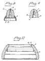
- the bell-like components 2 of the embodiment illustrated in Figs. 6-10 have a generally paraboloidal central part 7 that includes an axially through-penetrating bore 21 and a flat transverse underside 22.
- the bore 21 includes a widened intermediate part for accommodating a knot on the bottom end of an associated line 3, and a further widened bottom part for receiving a closure plug or stopper (not shown).
- the peripheral part 8 has the form of an outwardly and downwardly extending skirt of circular cross-section and relatively small material thickness. Provided on the inside of the skirt part 8 is a downwardly facing collar 23.
- the radially outermost region 24 of the part 7 includes a circumferentially extending groove 25 which is intended to receive an upper, radially inwardly facing and circumferentially extending portion 26 of the part 8.
- a radial edge 27 will snap-in behind a corresponding edge in the groove 25 so as to mechanically interlock the parts 7, 8.
- the dimensions of the upper portion 26 of part 8 and the collar 23 in relation to the outermost region 24 of part 7 is such that the collar 23 will lie against the region 24 and extend slightly beneath the surface 22 subsequent to assembling the parts 7, 8, such that part 8 is prevented from further downward movement in relation to part 7.
Landscapes
- Health & Medical Sciences (AREA)
- General Health & Medical Sciences (AREA)
- Pediatric Medicine (AREA)
- Toys (AREA)
- Prostheses (AREA)
Abstract
Description
Claims (10)
- A toy that includes at least one component (1; 2) that has a central part and a peripheral part which surrounds the central part and has a small thickness in comparison with said central part, characterized in that said component parts comprise a separate central part (5; 7) and a separate peripheral part (6; 8) that embraces said central part and is connected thereto and comprised of a material which is tougher than the material from which the central part is made.
- A toy according to Claim 1, characterized in that the peripheral part (6; 8) embraces the central part (5; 7) while exerting an inwardly acting pressure thereon.
- A toy according to Claim 1 or 2, characterized in that the central part (5; 7) and the peripheral part (6; 8) are interlocked mechanically in an axial direction.
- A toy according to any one of Claims 1-3, characterized in that the central part (5; 7) is made of wood and the surrounding peripheral part (6; 8) is made of tough, plastic material.
- A toy according to Claim 4, characterized in that the central part (5; 7) is rotationally symmetrical about an axis that extends generally parallel with the grain of the wood.
- A toy according to Claim 5, characterized in that the peripheral part (6; 8) includes a generally axially angled collar (16) which surrounds the radially outermost region (11; 24) of the central part while exerting radially and inwardly acting pressure thereon.
- A toy according to Claim 6, characterized in that the collar (16; 23) extends downwards in relation to the peripheral part (6; 8).
- A toy according to Claim 6 or 7, characterized in that the central part (5; 7) includes a peripheral groove (18; 25) that accommodates at least one radially and inwardly directed projection (17; 26) on the inner surface of the collar (16) or of the peripheral part (8).
- A toy according to any one of Claims 6-8, characterized in that the central part (7) has a generally paraboloidal shape and is terminated at its bottom by a transverse surface (22), wherewith the bottom region of the central part is surrounded by a skirt-like peripheral part (8) whose collar (23) in pressing engagement with the central part (7) reaches at least down to said transverse terminating surface (22) on the central part (7).
- A toy according to any one of Claims 1-9, characterized in that the central part (5; 7) has a largest cross-sectional size of at least 32 mm.
Applications Claiming Priority (3)
| Application Number | Priority Date | Filing Date | Title |
|---|---|---|---|
| SE9603335A SE9603335L (en) | 1996-09-13 | 1996-09-13 | Mobile-type toy |
| SE9603335 | 1996-09-13 | ||
| PCT/SE1997/001476 WO1998010850A1 (en) | 1996-09-13 | 1997-09-04 | A toy |
Publications (2)
| Publication Number | Publication Date |
|---|---|
| EP0927072A1 EP0927072A1 (en) | 1999-07-07 |
| EP0927072B1 true EP0927072B1 (en) | 2003-03-12 |
Family
ID=20403870
Family Applications (1)
| Application Number | Title | Priority Date | Filing Date |
|---|---|---|---|
| EP97939293A Expired - Lifetime EP0927072B1 (en) | 1996-09-13 | 1997-09-04 | A toy |
Country Status (6)
| Country | Link |
|---|---|
| US (1) | US6089944A (en) |
| EP (1) | EP0927072B1 (en) |
| AT (1) | ATE234136T1 (en) |
| DE (1) | DE69719767D1 (en) |
| SE (1) | SE9603335L (en) |
| WO (1) | WO1998010850A1 (en) |
Families Citing this family (5)
| Publication number | Priority date | Publication date | Assignee | Title |
|---|---|---|---|---|
| US7762865B2 (en) * | 2007-01-23 | 2010-07-27 | Infantino, Llc | Crib mobile with animated characters |
| USD830472S1 (en) | 2016-08-04 | 2018-10-09 | Skip Hop, Inc. | Infant mobile |
| USD820918S1 (en) * | 2017-08-24 | 2018-06-19 | Jing Zhong | Finger spinner |
| US10499659B2 (en) * | 2018-02-05 | 2019-12-10 | Jeffery Dean Papenfus | Windpipe removal device and method |
| WO2022197809A1 (en) * | 2021-03-16 | 2022-09-22 | Hb Innovations, Inc. | Mobile hub |
Family Cites Families (8)
| Publication number | Priority date | Publication date | Assignee | Title |
|---|---|---|---|---|
| US2397061A (en) * | 1944-10-23 | 1946-03-19 | Lloyd L Toalson | Sounding toy |
| GB1172565A (en) * | 1966-02-10 | 1969-12-03 | Hilary Page Sensible Toys Ltd | Improved Baby's Toy |
| US3521883A (en) * | 1967-11-27 | 1970-07-28 | Frank G Hamilton | Baseball bat with training weight |
| GB1306039A (en) * | 1971-02-01 | 1973-02-07 | ||
| EP0213662A1 (en) * | 1985-08-05 | 1987-03-11 | Joseph Louis Blankenzee | Jump ball |
| US5050877A (en) * | 1988-10-27 | 1991-09-24 | Alan Wales | Warm-up weight for softball bat |
| US5045011A (en) * | 1990-06-01 | 1991-09-03 | Lovik Craig J | Flying balloon toy |
| US5395107A (en) * | 1993-10-12 | 1995-03-07 | De Pippo; Richard J. | Hitting training attachment apparatus |
-
1996
- 1996-09-13 SE SE9603335A patent/SE9603335L/en not_active IP Right Cessation
-
1997
- 1997-09-04 WO PCT/SE1997/001476 patent/WO1998010850A1/en not_active Ceased
- 1997-09-04 AT AT97939293T patent/ATE234136T1/en not_active IP Right Cessation
- 1997-09-04 EP EP97939293A patent/EP0927072B1/en not_active Expired - Lifetime
- 1997-09-04 DE DE69719767T patent/DE69719767D1/en not_active Expired - Lifetime
- 1997-09-04 US US09/147,243 patent/US6089944A/en not_active Expired - Fee Related
Also Published As
| Publication number | Publication date |
|---|---|
| DE69719767D1 (en) | 2003-04-17 |
| SE505998C2 (en) | 1997-11-03 |
| ATE234136T1 (en) | 2003-03-15 |
| US6089944A (en) | 2000-07-18 |
| SE9603335D0 (en) | 1996-09-13 |
| EP0927072A1 (en) | 1999-07-07 |
| SE9603335L (en) | 1997-11-03 |
| WO1998010850A1 (en) | 1998-03-19 |
Similar Documents
| Publication | Publication Date | Title |
|---|---|---|
| US5194031A (en) | Toy gear assembly | |
| US5792496A (en) | Edible shell/thermoplastic container system | |
| USD309280S (en) | Pacifier coupler for baby's garment | |
| US3816957A (en) | Connecting means for connecting relatively soft parts of a doll | |
| US6666740B1 (en) | Stuffed toy with attached pacifier | |
| US2540369A (en) | Toy bead chain | |
| US3014307A (en) | Child's amusement device | |
| USD348124S (en) | Play toy for cats | |
| USD306071S (en) | Baby bottle neck ring | |
| US4182073A (en) | Twin flying saucer toy | |
| US6390879B1 (en) | Flying disc toy | |
| US6089944A (en) | Toy | |
| US4674987A (en) | Toy for amusement and/or exercise | |
| US4096659A (en) | Spin the saucer | |
| USD306074S (en) | Baby bottle neck ring | |
| US4281472A (en) | Finger toy | |
| USD331783S (en) | Combined pacifier, teething ring and rattle | |
| USD326148S (en) | Fan for infants and children | |
| USD306072S (en) | Baby bottle neck ring | |
| WO2002078495A1 (en) | A safety feeding utensil | |
| US5137334A (en) | Safety device for restraining a child in a chair | |
| US5362067A (en) | Throwable toy having a ring arrangement of many extended fibers having one end of each fiber held with other fiber ends in a set of twisted wires arranged and joined together in a ring | |
| USD377812S (en) | Child's rocking toy | |
| USD279050S (en) | Childs toy | |
| AU664048B2 (en) | A jointed plaything, for example in the form of a small animal or doll |
Legal Events
| Date | Code | Title | Description |
|---|---|---|---|
| PUAI | Public reference made under article 153(3) epc to a published international application that has entered the european phase |
Free format text: ORIGINAL CODE: 0009012 |
|
| 17P | Request for examination filed |
Effective date: 19981030 |
|
| AK | Designated contracting states |
Kind code of ref document: A1 Designated state(s): AT BE CH DE DK FI FR GB IT LI |
|
| GRAH | Despatch of communication of intention to grant a patent |
Free format text: ORIGINAL CODE: EPIDOS IGRA |
|
| RIN1 | Information on inventor provided before grant (corrected) |
Inventor name: BERGKVIST, HAKAN |
|
| GRAH | Despatch of communication of intention to grant a patent |
Free format text: ORIGINAL CODE: EPIDOS IGRA |
|
| GRAA | (expected) grant |
Free format text: ORIGINAL CODE: 0009210 |
|
| AK | Designated contracting states |
Designated state(s): AT BE CH DE DK FI FR GB IT LI |
|
| PG25 | Lapsed in a contracting state [announced via postgrant information from national office to epo] |
Ref country code: LI Free format text: LAPSE BECAUSE OF FAILURE TO SUBMIT A TRANSLATION OF THE DESCRIPTION OR TO PAY THE FEE WITHIN THE PRESCRIBED TIME-LIMIT Effective date: 20030312 Ref country code: IT Free format text: LAPSE BECAUSE OF FAILURE TO SUBMIT A TRANSLATION OF THE DESCRIPTION OR TO PAY THE FEE WITHIN THE PRESCRIBED TIME-LIMIT;WARNING: LAPSES OF ITALIAN PATENTS WITH EFFECTIVE DATE BEFORE 2007 MAY HAVE OCCURRED AT ANY TIME BEFORE 2007. THE CORRECT EFFECTIVE DATE MAY BE DIFFERENT FROM THE ONE RECORDED. Effective date: 20030312 Ref country code: FR Free format text: LAPSE BECAUSE OF FAILURE TO SUBMIT A TRANSLATION OF THE DESCRIPTION OR TO PAY THE FEE WITHIN THE PRESCRIBED TIME-LIMIT Effective date: 20030312 Ref country code: FI Free format text: LAPSE BECAUSE OF FAILURE TO SUBMIT A TRANSLATION OF THE DESCRIPTION OR TO PAY THE FEE WITHIN THE PRESCRIBED TIME-LIMIT Effective date: 20030312 Ref country code: CH Free format text: LAPSE BECAUSE OF FAILURE TO SUBMIT A TRANSLATION OF THE DESCRIPTION OR TO PAY THE FEE WITHIN THE PRESCRIBED TIME-LIMIT Effective date: 20030312 Ref country code: BE Free format text: LAPSE BECAUSE OF FAILURE TO SUBMIT A TRANSLATION OF THE DESCRIPTION OR TO PAY THE FEE WITHIN THE PRESCRIBED TIME-LIMIT Effective date: 20030312 Ref country code: AT Free format text: LAPSE BECAUSE OF FAILURE TO SUBMIT A TRANSLATION OF THE DESCRIPTION OR TO PAY THE FEE WITHIN THE PRESCRIBED TIME-LIMIT Effective date: 20030312 |
|
| REG | Reference to a national code |
Ref country code: GB Ref legal event code: FG4D |
|
| REG | Reference to a national code |
Ref country code: CH Ref legal event code: EP |
|
| REF | Corresponds to: |
Ref document number: 69719767 Country of ref document: DE Date of ref document: 20030417 Kind code of ref document: P |
|
| PG25 | Lapsed in a contracting state [announced via postgrant information from national office to epo] |
Ref country code: DK Free format text: LAPSE BECAUSE OF FAILURE TO SUBMIT A TRANSLATION OF THE DESCRIPTION OR TO PAY THE FEE WITHIN THE PRESCRIBED TIME-LIMIT Effective date: 20030612 |
|
| PG25 | Lapsed in a contracting state [announced via postgrant information from national office to epo] |
Ref country code: DE Free format text: LAPSE BECAUSE OF FAILURE TO SUBMIT A TRANSLATION OF THE DESCRIPTION OR TO PAY THE FEE WITHIN THE PRESCRIBED TIME-LIMIT Effective date: 20030613 |
|
| PG25 | Lapsed in a contracting state [announced via postgrant information from national office to epo] |
Ref country code: GB Free format text: LAPSE BECAUSE OF NON-PAYMENT OF DUE FEES Effective date: 20030904 |
|
| REG | Reference to a national code |
Ref country code: CH Ref legal event code: PL |
|
| PLBE | No opposition filed within time limit |
Free format text: ORIGINAL CODE: 0009261 |
|
| STAA | Information on the status of an ep patent application or granted ep patent |
Free format text: STATUS: NO OPPOSITION FILED WITHIN TIME LIMIT |
|
| EN | Fr: translation not filed | ||
| 26N | No opposition filed |
Effective date: 20031215 |
|
| GBPC | Gb: european patent ceased through non-payment of renewal fee |