EP0926464A2 - Stylus surface property measuring device with elongated slide block - Google Patents
Stylus surface property measuring device with elongated slide block Download PDFInfo
- Publication number
- EP0926464A2 EP0926464A2 EP98310341A EP98310341A EP0926464A2 EP 0926464 A2 EP0926464 A2 EP 0926464A2 EP 98310341 A EP98310341 A EP 98310341A EP 98310341 A EP98310341 A EP 98310341A EP 0926464 A2 EP0926464 A2 EP 0926464A2
- Authority
- EP
- European Patent Office
- Prior art keywords
- detector
- measuring device
- surface property
- stylus
- property measuring
- Prior art date
- Legal status (The legal status is an assumption and is not a legal conclusion. Google has not performed a legal analysis and makes no representation as to the accuracy of the status listed.)
- Granted
Links
Images


Classifications
-
- G—PHYSICS
- G01—MEASURING; TESTING
- G01B—MEASURING LENGTH, THICKNESS OR SIMILAR LINEAR DIMENSIONS; MEASURING ANGLES; MEASURING AREAS; MEASURING IRREGULARITIES OF SURFACES OR CONTOURS
- G01B7/00—Measuring arrangements characterised by the use of electric or magnetic techniques
- G01B7/34—Measuring arrangements characterised by the use of electric or magnetic techniques for measuring roughness or irregularity of surfaces
Definitions
- the present invention relates to a surface property measuring device comprising a detector having a stylus for measuring surface property, typically, surface roughness, and a driving mechanism for causing the detector to advance and retreat along a surface to be measured, more particularly to a surface property measuring device which is superior in straightness and reproducibility exhibited when the detector advances and retreats, and which is low in cost.
- the present invention relates to a surface property measuring device comprising a detector having a stylus arm provided with the stylus in the vicinity of a leading end thereof, and more particularly to a surface property measuring device comprising a detector which is capable of measuring micro surface property by a low measuring force.
- a surface roughness measuring device of applying a stylus on a surface to be measured, and measuring the surface roughness by detecting a surface roughness-direction-wise displacement of the stylus while advancing and retreating a detector including the stylus along the surface to be measured, to thereby convert the detected displacement into an electrical signal and then process the electrical signal in a predetermined manner.
- a surface roughness measuring device comprising a sliding shaft 34 held on a bearing 33, which is disposed on a frame 32 of the driving mechanism, and sliding in an advancing and retreating direction (in the direction shown by the arrow A) of a detector 10, a driving-side connector 40 attached to the sliding shaft 34 through a moving block 36 and a leaf spring 38, a feed block 44 fixed to the sliding shaft 34 through a connecting portion 42 for causing the sliding shaft 34 to advance and retreat in the direction shown by the arrow A, a feed screw 46 engaged with the feed block 44, a reduction gear 50 connected to the feed screw 46 through a coupling 48, and a motor 52 for rotation-driving the reduction gear 50.
- reference numeral 14 designates a detector-side connector pin attached to a rear end (on the right-hand end-of the drawing) of a case 12 of the detector 10 and engaged with the driving-side connector 40, 18 a stylus arm having a stylus 16, which moves up and down while following the surface to be measured, at a leading end thereof (on the left-hand end of the drawing) and swinging in the case 12 with a fulcrum (20) as a center, 20 a leaf spring shaped like a substantially L, constituting the fulcrum of the stylus arm 18, 22 an inductance type displacement detector disposed in the vicinity of a rear end of the stylus arm 18 for detecting an up-and-down movement of the rear end of the stylus lever 18, 24 a skid for absorbing minute irregularities in the vicinity of the stylus 16 to thereby obtain a stable measured value, and 26 a nose for protecting the stylus 16 and the stylus arm 18.
- This Japanese Patent Publication (Kokoku) No. 4-60523 aims to propose a compact stationary surface roughness measuring device.
- the sliding shaft 34 itself advances and retreats in the frame 32 of the driving mechanism 30 in the direction shown by the arrow A, thereby disabling the sliding shaft 34 to be elongated so much, which causes the moving stroke of the detector 10 to be placed under restriction.
- the sliding shaft 34 as a moving part is connected to the detector 10 through the moving block 36, the leaf spring 38, the connector 40, and so on, thereby making the bearing 33 susceptible to the external force, which provides problems of making it difficult to maintain a stable and highly accurate straightness, and so on.
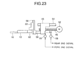
- a stylus type measuring device in which, as its main part is shown in Fig. 23, a guide shaft 54 is fixed to a frame of a driving mechanism (not shown) in parallel with an advancing and retreating direction of a detector 10 (in a lateral direction of the drawing), and the detector 10 is attached to a feed nut 45 which slides on the guide shaft 54 and is moved by a feed screw 46 rotated by a motor 52.
- reference numeral 16 is a stylus, 56 a slide rod fixed to the feed nut 45, 58 a vertical guiding member vertically connected to a leading end of the slide rod 56, 60 is a sliding member attached to the vertical guiding member 58 slidably up and down, 62 a holding member to hold the detector 10 rotatably attached to the sliding member 60, 64 a switch pin fixed to the feed nut 45, and 66, 68 are a fore end and a rear end limit switch which turn on at an advancing limit position (hereinafter referred to as "the fore end”) or an retreating limit position (hereinafter referred to as "the rear end").
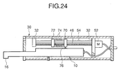
- a guide shaft 54 is fixed to a frame 32 of a driving mechanism 30 in parallel with an advancing and retreating direction of the detector 10 (in a lateral direction of the drawing), and the detector 10 is attached to one of a pair of movable pieces 70, 72 (the movable piece 70 in the drawing) which are moved by a feed screw 46 rotated by a motor 52.
- reference numeral 74 designates a pair of tension springs for urging both the movable pieces 70, 72 in the direction nearer to each other to thereby eliminate the backlash.
- the wire to the detector 10 in the driving mechanism 30 is made of a lead wire; therefore, according to the kind of the wire or the wiring manner of the wire, a part of the wire easily undergoes excessive bending, an unstable load, or the like is applied to a connector with the detector and a driving mechanism such as a sliding member, which provides a bad influence to the straightness and the reproducibility.
- a mechanism for supporting a stylus arm 18 in the detector 10 and providing a measuring force thereto not only a mechanism provided with one leaf spring 20 having both of a function as a fulcrum and a function of providing a measuring force, as shown in Japanese Patent Publication (Kokoku) No. 4-60523, but also a mechanism in which, as proposed in Japanese Patent Publication (Kokoku) No. 3-30084 and Japanese Provisional Patent Publication (Kokai) No. 6-258003, a coil spring 86 is, as shown in Fig.
- the mechanism using a bearing proposed in Japanese Patent Publication (Kokoku) No. 3-30084 and the mechanism using two coil springs, proposed in Japanese Provisional Utility Model Publication (Kokai) No. 1-104504, have many components, which provides a problem that the assembling and the adjustment are difficult.
- the mechanism which eliminates the backlash of the fulcrum and adjusts the measuring force by one coil spring proposed in Japanese Patent Publication (Kokoku) No. 3-30084, makes it difficult to set the optimum points of the both.
- a special detector such as a deep-slot-use prove detector having a long stylus has a problem that the change of the weight of the stylus arm causes the measuring force to change.
- the present invention has been made in order to solve the above-mentioned conventional problems. It is therefore a first object of the present invention to make the sliding member not to be affected by the external force, and then reduce the saccadic movement of the sliding member due to the dimension error, thereby stably being affected by a straightness with high accuracy at a low cost.
- the invention of claim 1 provides a surface property measuring device comprising a detector having a stylus, and a driving mechanism for causing the detector to advance and retreat along a surface to be measured, wherein the device comprising a columnar guide fixed to a frame of the driving mechanism in parallel with an advancing and retreating direction of the detector, a sliding member sliding on the columnar guide, elongated in the advancing and retreating direction of the detector, and engaged with the columnar guide at least two of a fore and a rear location thereof, and driving means for causing the sliding member to advance and retreat along the columnar guide, and wherein the detector is attached to the sliding member, which results in solution of the above-mentioned first object.
- the columnar guide can be elongated, and portions of the sliding member for receiving the sliding portion can be arranged with its span wide, which makes the sliding member not to be affected by the external force, and then reduces the saccadic movement of the sliding member due to the dimension error, thereby stably providing a straightness with high accuracy at a low cost.
- the columnar guide is provided in plural, and one of the columnar guides is inserted through the sliding member, whereas the others of the columnar guides is adapted to press the sliding member, so as to obtain more stability.
- the sliding member is shaped like a substantially O which is elongated in the advancing and retreating direction of the detector, and the one of the columnar guides is inserted through two of the fore and the rear location.
- the detector is detachable to the driving mechanism through connectors, wherein a driving-side connector is fixed to the sliding member.
- At least a portion of a cable, which connects the driving mechanism with the detector, to be deformed due to a movement of the detector comprises a flexible printed circuit board, which results in solution of the above-mentioned second object.
- the invention of claim 6 provides a surface property measuring device comprising a stylus arm having a stylus at the vicinity of a leading end thereof, wherein a fulcrum of the stylus arm is made of a thin plate, and the stylus arm is applied with a force directed in such a direction as to cause the stylus to contact to a surface to be measured, by means of a coil spring which is independent of the thin plate, which results in solution of the above-mentioned third object.
- no bearing is used, thereby reducing the number of the components and making the assembling and the adjustment easy, with low cost.
- the fulcrum is fixed using the thin plate, thereby preventing the fulcrum shaft from shifting, with stabilized accuracy.
- the thickness change and the bend of the leaf causes the measuring force to be changed, thereby making the adjustment difficult; however, the invention of claim 6 is capable of setting the measuring force in designing, and easily adjusting the measuring force.
- the thickness change and the bend of the leaf, and the like provide a large fluctuation, thereby making it difficult to set the optimum points of both of eliminating the saccadic movement and adjusting the measuring force.
- the coil spring has only to be adjusted taking account of the optimum measuring force only, which makes it easy to adjust the measuring force.
- a special detector such as a deep-slot-use detector having a long stylus
- the dispersion of the measuring force among the products can be lowered by changing the thickness and the shape of the leaf spring and simultaneously adjusting the urging force of the coil spring.
- the thin plate is more different (weaker) in elastic force in the vicinity of the fulcrum than at the other portions, so as to reduce fluctuations in position of the fulcrum.
- the thin plate is shaped like a cross and fixed to a frame of the detector at both end portions thereof, and a stylus arm is fixed to a center portion of the thin plate, so as to prevent fluctuations in position of the fulcrum.
- an urging force of the coil spring is adjustable.
- the thin plate comprises a leaf spring, and the leaf spring provides a reaction force which is opposed to an urging force by the coil spring, and the balance between the reaction force and the urging force by the coil spring provides a measuring force to the stylus, which provides a minute measuring force with high accuracy.
- Fig. 1 is a perspective view showing the construction of a main part of a first embodiment of the present invention
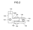
- Fig. 2 is a side view viewed from the direction shown by the arrow II in Fig. 1
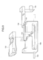
- Fig. 3 is a longitudinal sectional view, viewed from its front, of a driving mechanism to which a detector according to a first embodiment is attached
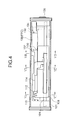
- Fig. 4 is a longitudinal sectional view of the same viewed from above
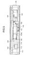
- Fig. 5 is a longitudinal sectional view of the same viewed from the bottom
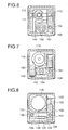
- Fig. 6 is a lateral sectional view taken on the line VI-VI in Fig. 4
- Fig. 7 is a lateral sectional view taken on the line VII-VII in Fig. 4
- Fig. 8 is a lateral sectional view taken on the line VIII-VIII in Fig. 4.
- a driving mechanism 100 comprises a main shaft (columnar guide) 104 and a sub shaft (columnar guide) 106 which are fixed to a frame 102 of the driving mechanism 100, a slide block (sliding member) 108, which is shaped like a substantially O elongated in an advancing and retreating direction (in the direction shown by the arrow A) of a detector, sliding on the shafts 104, 106, the main shaft 104 being inserted through at two of a fore and a rear location thereof, an interlinking rod 110 and a feed nut 112 causing the slide block 108 to advance and retreat along the shafts 104, 106, a feed screw 114 screwed with the feed nut 112, and a gear motor 118 for rotating the feed screw 114 through a flexible coupling 116.
- a detector mount 108A is formed on a rear end of the slide block 108, and to a lower side of the slide block 108 are fixed by bolts 122 both of a leaf spring 152 attached to a rear end of a connector housing 150 for containing a detector 200, for providing a skid pressure, and a shaft supporting plate 120 for pressing a lower surface of the sub shaft 106. Further, a leaf spring 126, on which a sliding plate 124 for pressing an upper side of the sub shaft 106, is fixed on an upper side of the detector mount 108A through bolts 128.
- reference numeral 101 designates a case of a driving mechanism 130; a switch pin uprightly planted on the slide block 108; 132 and 143 a fore and a rear end switch engaging with the switch pin 130 to stop or reverse the gear motor 118; 140 a detector lift plate fixed to the frame 102 through a bolt 142 for engaging with an angle-like protrusion 150A formed outside the connector housing 150 in the vicinity of a retreating limit position of the detector 200 to lift the detector 200, thereby preventing a stylus 202 and a skid 204 from protruding downward a bottom surface of the driving mechanism 100; 154 a driving-side connector contained in the connector housing 150; 206 a detector-side connector pin inserted into the driving-side connector 154; 208 a connector housing of the detector, and 210 a nose of the same.
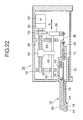
- the driving mechanism 100 can be contained in an electrical equipment section 300, as shown in Figs. 13 to 15 described later. On a rear end of the driving mechanism 100 is disposed an electrical equipment-side connector 136 electrically connected to the electrical equipment section 300, and a portion between the electrical equipment-side connector 136 and the driving-side connector 154 is wired by a thin flexible printed circuit substrate (FPC) 138, having a thickness of, e.g. about 0.2 mm, through the connector housing 150.
- FPC thin flexible printed circuit substrate
- the flexible printed circuit substrate 138 is, as shown in Fig. 9, fixed to the connector housing 150 and the electrical equipment-side connector 136 by the soldering at both ends thereof, fixed to the slide block 108 by the screw 139 at an intermediate portion, and then contained in the driving mechanism 100 in a U-like sagged manner, thereby causing the change of the wire length due to the movement of the connector 154 to be absorbed, which prevents the detector 200 from receiving the tension even if the connector housing 150 (detector 200) is moved.
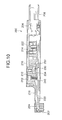
- the detector 200 mainly comprises, as shown in Fig. 10 (longitudinal sectional view) and Fig. 11 (exploded perspective view viewed obliquely from below), a main body frame 212 having a displacement-detecting bobbin 214 at a rear end thereof, a stylus arm 220 having a surface roughness-measuring stylus 202 in the vicinity of a leading end thereof and a displacement-detecting core 222 in the vicinity of a rear end thereof, a plane shaped fulcrum leaf spring 230, shown in Fig. 12, for fixing a central portion, for example, of the stylus arm 220 to the main body frame 212, a coil spring 240 for applying a force, which is directed in such a direction (downward direction in Fig. 9) as to contact the stylus 202 to a surface to be measured, to the stylus arm 220, and a spring pressing screw 242 for adjusting an urging force due to the coil spring 240.
- the fulcrum leaf spring 230 is fixed to the main body frame 212 by screws 232, and fixed to the stylus arm 220 by screws 234.
- reference numeral 216 designates a cover.
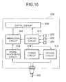
- the electrical equipment section 300 mainly comprises, as shown in Fig. 13 (front view), Fig. 14 (plan view), Fig. 15 (bottom view), and Fig. 16 (block diagram), a signal processing circuit 304 for processing a signal, which is obtained from the detector 200 contained in the driving mechanism 100, through a cable 302 connected with the electric equipment-side connector 136, a measuring circuit 306 for obtaining a surface roughness corresponding to various kinds of parameters based on the signal from the signal processing circuit 304, a digital display 308 for displaying the measured value obtained by the measuring circuit 306, a driving circuit 310 for driving the gear motor 118 in the driving mechanism 100 through the cable 302, a control circuit 312 for controlling the driving circuit 310, the measuring circuit 306, and the digital display 308, and an electric power circuit 314 for supplying an electric power to the above respective circuit.
- a signal processing circuit 304 for processing a signal, which is obtained from the detector 200 contained in the driving mechanism 100, through a cable 302 connected with the electric equipment-side connector 136
- the solid line in the drawing shows the position of a leading end of the detector 200 exposed when measuring, and the one dot chain line shows the position of the leading end of the detector 200 exposed when it is housed in the electrical equipment section 300.
- reference numeral 320 designates an electric power switch, 322 a start switch, and 324 a parameter-selecting switch.
- a required measuring force is applied to the stylus 202 by adjusting an amount of inserting the spring pressing screw 242 according to an object to be measured.
- the object to be measured it is, as shown in Figs. 13 to 15, selected whether the driving mechanism 100 is used in such a manner that it is housed in the electrical equipment section 300, or the driving mechanism 100 is independently used in such a manner that it is separated from the electrical equipment section 300. For example, when measuring an inner surface of a small hole, the measurement is made with the driving mechanism 100 removed because the electric equipment section 300 is obstructive, and with the driving mechanism 100 united to the electric equipment section 300 in the other cases.
- the stylus 202 of the detector 200 is contacted to a surface to be measured, the electric power switch 320 is turned on, and the start switch 322 is pressed. Then, the control circuit 312 causes the gear motor 118 to rotate through the driving circuit 310. When rotation of the gear motor 118 causes the feed screw 114 to rotate, the slide block 108 is moved in an axial direction of the feed screw 114; therefore, the stylus 202 of the detector 200 is displaced up and down according to the surface roughness of an article to be measured.
- the displacement of the stylus 202 is converted into an electrical signal by the detector 200, then transmitted to the signal processing circuit 304 through a cable 302. Thereafter, the processed signal is transmitted to the measuring circuit 306.
- the measuring circuit 306 obtains the surface roughness based on the signal transmitted from the signal processing circuit 304 according to the parameters instructed from the control circuit 312, and let it displayed on the digital display 308.
- the slide block 108 is shaped like a substantially O which is elongated in an advancing and retreating direction of the detector, and the main shaft 104 is passed through two of the fore and the rear end; therefore, a long span is realized by a reduced-weight and simple construction. Furthermore, not only the main shaft 104 but also the short sub shaft 106 are provided to press the detector mount 108A of the slide block 108, which provides, particularly, a high stability.
- the shape of the sliding member is not limited to a substantially O.
- the shape of the columnar guide is not limited to a circle column, and the number of the columnar guides is not limited to two.
- the shape of the sliding member can be shaped like a prism, only one main shaft can be provided, or more than two of long sub shafts can be provided.
- the wire to the driving-side connector 154 is made of the flexible printed circuit substrate 138, thereby causing the bend portion to be stabilized, which makes a load applied to the bend portion, and hence the load to the connector 154 constant.
- the wire to the driving-side connector can be made of a usual lead wire.
- the fulcrum leaf spring 230 is shaped like a simple rectangle, which makes the construction simple.
- the plate thickness of the fulcrum leaf spring may be changed according to an object to be measured, or a plate width-wise direction notch 230A may be disposed at a fulcrum location of the center portion to decrease the width, as shown by a variant example in Fig. 17, a thin thickness portion wall 230B may be provided, like another variant example shown in Fig. 18, or there may be provided a hollow 230C which weakens the resilient force of the vicinity of the fulcrum compared with the other portion, like further variant example shown in Fig. 19.
- the leaf spring 230 may be bent in such a direction as to press the coil spring 240, thereby causing a reaction force against the urging force by the coil spring 240 to be applied to the coil spring 240. Therefore, the balance between the reaction force and the urging force by the coil spring enables a measuring force to be applied to the stylus 202. In this case, a minute measuring force is so easily adjusted to cope with the difference of the measuring force according to the radius of curvature of a leading end of the stylus, or the difference of the weight of the stylus arm as an option such as the deep groove-use detector.
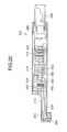
- the leaf spring may be made of a small resilient thin plate, or of a cross-like leaf spring 250 like a second embodiment shown in Fig. 20 (longitudinal sectional view) and Fig. 21 (bottom view of a stylus arm), and then its both ends may be fixed to the main frame 212 by screws 252, and its center may be fixed to the stylus arm 220 by screws 254.
- the both ends of the leaf spring 250 are fixed to the frame 212; therefore, particularly, the fulcrum position is stable.
- the invention is applied to the stationary portable surface roughness measuring device, the application of the invention is not limited thereto, and hence the invention can be applied to, for example, contour measuring devices, and surface roughness proves used for three-dimensional coordinates measuring machines.
Landscapes
- Physics & Mathematics (AREA)
- General Physics & Mathematics (AREA)
- A Measuring Device Byusing Mechanical Method (AREA)
- Length Measuring Devices With Unspecified Measuring Means (AREA)
Abstract
Description
Claims (12)
- A surface property measuring device comprising a detector (200) having a stylus (202), and a driving mechanism (100) for causing said detector (200) to advance and retreat along a surface to be measured, wherein said device comprising:a columnar guide (104) fixed to a frame (102) of said driving mechanism (100) in parallel with an advancing and retreating direction of said detector (200) ;a sliding member (108) sliding on said columnar guide (104), elongated in said advancing and retreating direction of said detector (200), and engaged with said columnar guide (104) at least two of a fore and a rear location thereof;
anddriving means for causing said sliding member (108) to advance and retreat along said columnar guide (104), and whereinsaid detector (200) is attached to said sliding member (108). - A surface property measuring device as claimed in claim 1, wherein said columnar guide is provided in plural (104,106), and one (104) of said columnar guides is inserted through said sliding member (108), whereas the others (106) of said columnar guides is adapted to press said sliding member (108).
- A surface property measuring device as claimed in claim 1 or 2, wherein said sliding member (108) is shaped like a substantially O which is elongated in said advancing and retreating direction of said detector (200), and said one (104) of said columnar guides is inserted through two of said fore and said rear location.
- A surface property measuring device as claimed in one of claims 1 to 3, wherein said detector (200) is detachable to said driving mechanism (100) through connectors (154,208), wherein a driving side-connector (154) is fixed to said sliding member (108).
- A surface property measuring device as claimed in one of claims 1 to 4, wherein at least a portion of a cable, which connects said driving mechanism (100) with said detector (200), to be deformed due to a movement of said detector (200) comprises a flexible printed circuit board (138).
- A surface property measuring device as claimed in claim 1, wherein said stylus (202) is disposed in the vicinity of a leading end of a stylus arm (220) which is made of a thin plate (230, 250), and a force, which is directed in such a direction as to cause said stylus (202) to contact to a surface to be measured, is applied to said stylus arm (220) by means of a coil spring (240) which is independent of said thin plate (230, 250).
- A surface property measuring device as claimed in claim 6, wherein said thin plate (230) is more different in elastic force in the vicinity of said fulcrum than at the other portions.
- A surface property measuring device as claimed in claim 7, wherein said thin plate (230) is weaker in elastic force in the vicinity of said fulcrum than at the other portions.
- A surface property measuring device as claimed in claim 6, wherein said thin plate (250) is shaped like a cross and fixed to a frame (212) of said detector (200) at both end portions thereof, and a stylus arm (220) is fixed to a center portion of said thin plate (250).
- A surface property measuring device as claimed in one of claims 6 to 9, wherein an urging force of said coil spring (240) is adjustable.
- A surface property measuring device as claimed in claims 6 to 10, wherein said thin plate comprises a leaf spring (230,250).
- A surface property measuring device as claimed in claim 11, wherein said leaf spring (230,250) provides a reaction force which is opposed to an urging force by said coil spring (240), and the balance between said reaction force and said urging force by said coil spring (240) provides a measuring force to said stylus (202).
Applications Claiming Priority (4)
| Application Number | Priority Date | Filing Date | Title |
|---|---|---|---|
| JP35888497 | 1997-12-26 | ||
| JP35888697A JP3534296B2 (en) | 1997-12-26 | 1997-12-26 | Surface texture measuring machine |
| JP35888497A JP3405515B2 (en) | 1997-12-26 | 1997-12-26 | Surface texture measuring machine |
| JP35888697 | 1997-12-26 |
Publications (3)
| Publication Number | Publication Date |
|---|---|
| EP0926464A2 true EP0926464A2 (en) | 1999-06-30 |
| EP0926464A3 EP0926464A3 (en) | 1999-10-13 |
| EP0926464B1 EP0926464B1 (en) | 2003-07-30 |
Family
ID=26580863
Family Applications (1)
| Application Number | Title | Priority Date | Filing Date |
|---|---|---|---|
| EP98310341A Expired - Lifetime EP0926464B1 (en) | 1997-12-26 | 1998-12-16 | Stylus surface property measuring device with elongated annular slide block |
Country Status (3)
| Country | Link |
|---|---|
| US (1) | US6397667B1 (en) |
| EP (1) | EP0926464B1 (en) |
| DE (1) | DE69816771T2 (en) |
Cited By (5)
| Publication number | Priority date | Publication date | Assignee | Title |
|---|---|---|---|---|
| WO2007028449A1 (en) * | 2005-07-27 | 2007-03-15 | Carl Mahr Holding Gmbh | Stylus-type instrument |
| DE10053939B4 (en) * | 1999-11-01 | 2014-05-15 | Mitutoyo Corp. | Instrument for measuring surface quality |
| DE10054113B4 (en) * | 1999-11-01 | 2015-01-08 | Mitutoyo Corp. | drive unit |
| CN115962738A (en) * | 2022-12-29 | 2023-04-14 | 孙晓寅 | Photovoltaic module plane straightness detection device |
| CN119492349A (en) * | 2025-01-17 | 2025-02-21 | 西安爱德华测量设备股份有限公司 | Coordinate measuring machine multi-modal measurement system and method |
Families Citing this family (19)
| Publication number | Priority date | Publication date | Assignee | Title |
|---|---|---|---|---|
| JP3443050B2 (en) * | 1999-10-21 | 2003-09-02 | 株式会社ミツトヨ | Attitude adjustment device |
| JP4305623B2 (en) * | 2002-03-13 | 2009-07-29 | セイコーエプソン株式会社 | Oscillator and vibratory gyroscope |
| US7231959B2 (en) * | 2002-05-02 | 2007-06-19 | International Truck Intellectual Property Company, Llc | Vehicle energy management system |
| JP4755429B2 (en) * | 2005-03-04 | 2011-08-24 | 株式会社ミツトヨ | Detector drive device |
| DE102005035786B3 (en) * | 2005-07-27 | 2007-01-04 | Carl Mahr Holding Gmbh | Roughness |
| USD579955S1 (en) | 2007-09-21 | 2008-11-04 | The Charles Machine Works, Inc. | Two wheel articulated tool carrier chassis |
| USD571827S1 (en) | 2007-09-21 | 2008-06-24 | The Charles Machine Works, Inc. | Two wheel articulated tool carrier chassis |
| USD579464S1 (en) | 2007-09-21 | 2008-10-28 | The Charles Machine Works, Inc. | Three-wheel articulated trencher |
| USD572730S1 (en) | 2007-09-21 | 2008-07-08 | The Charles Machine Works, Inc. | Four wheel articulated tool carrier |
| USD572275S1 (en) | 2007-09-27 | 2008-07-01 | The Charles Machine Works, Inc. | Articulated tool carrier with tower arm |
| USD572274S1 (en) | 2007-09-27 | 2008-07-01 | The Charles Machine Works, Inc. | Articulated dumper |
| EP2199732B1 (en) * | 2008-12-19 | 2017-10-11 | Klingelnberg AG | Device with roughness measuring probe |
| US9109330B2 (en) * | 2009-03-09 | 2015-08-18 | Honeywell International Inc. | Apparatus and method for measuring properties of unstabilized moving sheets |
| JP5485676B2 (en) * | 2009-12-16 | 2014-05-07 | 株式会社ミツトヨ | Surface texture measuring machine |
| JP6104557B2 (en) * | 2012-10-18 | 2017-03-29 | 株式会社ミツトヨ | Surface roughness measuring unit, 3D measuring device |
| CN104913709B (en) * | 2015-06-23 | 2018-04-03 | 南车戚墅堰机车有限公司 | Rotating shaft shaft extension taper contact surface detector |
| EP3228974B1 (en) * | 2016-04-06 | 2022-06-01 | Klingelnberg AG | Roughness measuring probe, device with roughness measuring probe and corresponding use |
| JP6458335B1 (en) * | 2018-02-07 | 2019-01-30 | 株式会社東京精密 | Surface shape measuring machine |
| CN108981534B (en) * | 2018-09-11 | 2024-02-27 | 江苏擎弓科技股份有限公司 | Detection device for composite plate spring |
Family Cites Families (27)
| Publication number | Priority date | Publication date | Assignee | Title |
|---|---|---|---|---|
| US3621580A (en) * | 1967-10-04 | 1971-11-23 | Tovaglieri & C Spa | Machine for the dimensional control of elements for nuclear fuels |
| US3852601A (en) * | 1971-07-15 | 1974-12-03 | Ital Elettionica Spa | Scanning device for scintigraphy according to three orthogonal planes |
| US3996669A (en) * | 1972-12-01 | 1976-12-14 | Finike Italiana Marposs-Soc. In Accomandita Semplice Di Mario Possati & C. | Wide-range device for measuring the linear sizes of mechanical workpieces |
| DE2613451C3 (en) * | 1976-03-30 | 1978-11-30 | C. Stiefelmayer Kg, 7300 Esslingen | Measuring and / or scribing device |
| US4050294A (en) | 1976-07-06 | 1977-09-27 | The Boeing Company | Apparatus and method of measuring surface roughness |
| DE2655049A1 (en) * | 1976-12-04 | 1978-06-08 | Bayerische Motoren Werke Ag | Transportable coordinate measuring probe - has interlocking support members to provide extended reference table |
| US4146966A (en) * | 1977-06-06 | 1979-04-03 | New Hermes, Incorporated | Engraving machine for rings and bangle bracelets |
| SE421562B (en) * | 1980-09-12 | 1982-01-04 | Samefa Ab | DEVICE AT A PLANT FOR DETERMINATION AND POSSIBLE CORRECTION OF THE BODY OF SELECTED CHECK POINTS OF A VEHICLE BODY OR CHASSIS |
| DE3147354A1 (en) | 1981-11-30 | 1983-06-09 | Hommelwerke GmbH, 7730 Villingen-Schwenningen | Device for applying a length touch probe to the surface of a measurement object |
| JPS61155701A (en) | 1984-12-27 | 1986-07-15 | Mitsutoyo Mfg Co Ltd | Automatic feed type measuring machine |
| JPS61155901A (en) | 1984-12-28 | 1986-07-15 | Mitsutoyo Mfg Co Ltd | Probe type measuring machine |
| JPS62194401A (en) * | 1985-08-08 | 1987-08-26 | Tokyo Seimitsu Co Ltd | Laid-on type surface roughness measuring instrument |
| CH668123A5 (en) * | 1985-11-12 | 1988-11-30 | Hans Meyer | DEVICE FOR MEASURING ALTITUDE DISTANCES. |
| DE3623362A1 (en) * | 1986-07-11 | 1988-01-21 | Opel Adam Ag | MEASURING AND TESTING DEVICE FOR DETERMINING THE ARC LENGTH OF SEMI-CIRCULAR BEARING SHELLS |
| DE3700053C1 (en) * | 1987-01-02 | 1988-01-07 | Erowa Ag | Backlash-free, switchable friction reversing gear |
| JPH0424408Y2 (en) * | 1987-05-12 | 1992-06-09 | ||
| DE3722876A1 (en) * | 1987-07-10 | 1989-01-19 | Zett Mess Technik Gmbh | Height-measuring and marking-out device |
| JPH01104504U (en) | 1987-12-29 | 1989-07-14 | ||
| JPH044Y2 (en) | 1989-01-26 | 1992-01-06 | ||
| IT1232093B (en) * | 1989-05-08 | 1992-01-23 | Dea Spa | MEASURING MACHINE PROVIDED WITH HANDLE MEANS FOR MOVING A MEASURING HEAD OF THE MACHINE SAME ALONG THREE AXES |
| DE3936463A1 (en) * | 1989-11-02 | 1991-05-08 | Zeiss Carl Fa | COORDINATE MEASURING DEVICE |
| DE4005292A1 (en) * | 1990-02-20 | 1991-08-22 | Zeiss Carl Fa | COORDINATE MEASURING DEVICE |
| DE4132724C2 (en) | 1991-10-01 | 1995-09-28 | Perthen Feinpruef Gmbh | Feed device |
| JP2853794B2 (en) | 1993-03-04 | 1999-02-03 | 株式会社東京精密 | Measurement force adjusting means of surface profile measuring machine |
| GB2281779B (en) | 1993-09-14 | 1997-04-23 | Rank Taylor Hobson Ltd | Metrological instrument |
| DE4433917A1 (en) * | 1994-09-23 | 1996-03-28 | Zeiss Carl Fa | Method for measuring workpieces with a hand-held coordinate measuring machine |
| DE4437033C2 (en) | 1994-10-17 | 1996-08-22 | Mahr Gmbh Goettingen | Feeder for surface measurement using the tactile cut method |
-
1998
- 1998-12-15 US US09/210,987 patent/US6397667B1/en not_active Expired - Lifetime
- 1998-12-16 DE DE69816771T patent/DE69816771T2/en not_active Expired - Lifetime
- 1998-12-16 EP EP98310341A patent/EP0926464B1/en not_active Expired - Lifetime
Cited By (5)
| Publication number | Priority date | Publication date | Assignee | Title |
|---|---|---|---|---|
| DE10053939B4 (en) * | 1999-11-01 | 2014-05-15 | Mitutoyo Corp. | Instrument for measuring surface quality |
| DE10054113B4 (en) * | 1999-11-01 | 2015-01-08 | Mitutoyo Corp. | drive unit |
| WO2007028449A1 (en) * | 2005-07-27 | 2007-03-15 | Carl Mahr Holding Gmbh | Stylus-type instrument |
| CN115962738A (en) * | 2022-12-29 | 2023-04-14 | 孙晓寅 | Photovoltaic module plane straightness detection device |
| CN119492349A (en) * | 2025-01-17 | 2025-02-21 | 西安爱德华测量设备股份有限公司 | Coordinate measuring machine multi-modal measurement system and method |
Also Published As
| Publication number | Publication date |
|---|---|
| EP0926464A3 (en) | 1999-10-13 |
| US6397667B1 (en) | 2002-06-04 |
| DE69816771D1 (en) | 2003-09-04 |
| EP0926464B1 (en) | 2003-07-30 |
| DE69816771T2 (en) | 2004-03-04 |
Similar Documents
| Publication | Publication Date | Title |
|---|---|---|
| EP0926464B1 (en) | Stylus surface property measuring device with elongated annular slide block | |
| US6807840B2 (en) | Crimping pliers with adjustable crimping gauge | |
| JP4607054B2 (en) | Optical fiber cutting device | |
| EP1482272A2 (en) | Measuring head | |
| JPH0714827Y2 (en) | Electronic balance equipped with a calibration weight device | |
| US4765181A (en) | Surface texture measuring instrument | |
| US4613246A (en) | Printer with mounting structure for print head | |
| HK86392A (en) | Measuring device for determining the dimensions of an object in three coordinates | |
| US5040288A (en) | Press tool | |
| DE10128624B4 (en) | Machine for measuring the construction of surfaces | |
| JP3640201B2 (en) | Surface texture measuring machine | |
| JP3405515B2 (en) | Surface texture measuring machine | |
| JP3534296B2 (en) | Surface texture measuring machine | |
| US5633469A (en) | Bonding load measuring device | |
| EP0106437B1 (en) | Measuring machine | |
| US4419825A (en) | Height gauge | |
| US6374682B1 (en) | Force-measuring apparatus, particularly a weighing cell I | |
| US6466884B2 (en) | Surface texture measuring machine and method of correcting a measured value for the machine | |
| JPH0449884B2 (en) | ||
| KR980008477A (en) | Masking tape cutting device | |
| US4848140A (en) | Guide device for a test body of a hardness measuring instrument | |
| KR960008012Y1 (en) | Inspection stage of contact image sensor | |
| JPH0449883B2 (en) | ||
| JPH0457201B2 (en) | ||
| JPH0544812Y2 (en) |
Legal Events
| Date | Code | Title | Description |
|---|---|---|---|
| PUAI | Public reference made under article 153(3) epc to a published international application that has entered the european phase |
Free format text: ORIGINAL CODE: 0009012 |
|
| AK | Designated contracting states |
Kind code of ref document: A2 Designated state(s): DE FR GB |
|
| AX | Request for extension of the european patent |
Free format text: AL;LT;LV;MK;RO;SI |
|
| PUAL | Search report despatched |
Free format text: ORIGINAL CODE: 0009013 |
|
| AK | Designated contracting states |
Kind code of ref document: A3 Designated state(s): AT BE CH CY DE DK ES FI FR GB GR IE IT LI LU MC NL PT SE |
|
| AX | Request for extension of the european patent |
Free format text: AL;LT;LV;MK;RO;SI |
|
| 17P | Request for examination filed |
Effective date: 20000321 |
|
| AKX | Designation fees paid |
Free format text: DE FR GB |
|
| 17Q | First examination report despatched |
Effective date: 20000615 |
|
| GRAH | Despatch of communication of intention to grant a patent |
Free format text: ORIGINAL CODE: EPIDOS IGRA |
|
| RTI1 | Title (correction) |
Free format text: STYLUS SURFACE PROPERTY MEASURING DEVICE WITH ELONGATED ANNULAR SLIDE BLOCK |
|
| RTI1 | Title (correction) |
Free format text: STYLUS SURFACE PROPERTY MEASURING DEVICE WITH ELONGATED ANNULAR SLIDE BLOCK |
|
| GRAH | Despatch of communication of intention to grant a patent |
Free format text: ORIGINAL CODE: EPIDOS IGRA |
|
| GRAA | (expected) grant |
Free format text: ORIGINAL CODE: 0009210 |
|
| AK | Designated contracting states |
Designated state(s): DE FR GB |
|
| REG | Reference to a national code |
Ref country code: GB Ref legal event code: FG4D |
|
| REF | Corresponds to: |
Ref document number: 69816771 Country of ref document: DE Date of ref document: 20030904 Kind code of ref document: P |
|
| ET | Fr: translation filed | ||
| PLBE | No opposition filed within time limit |
Free format text: ORIGINAL CODE: 0009261 |
|
| STAA | Information on the status of an ep patent application or granted ep patent |
Free format text: STATUS: NO OPPOSITION FILED WITHIN TIME LIMIT |
|
| 26N | No opposition filed |
Effective date: 20040504 |
|
| REG | Reference to a national code |
Ref country code: FR Ref legal event code: PLFP Year of fee payment: 18 |
|
| REG | Reference to a national code |
Ref country code: FR Ref legal event code: PLFP Year of fee payment: 19 |
|
| REG | Reference to a national code |
Ref country code: FR Ref legal event code: PLFP Year of fee payment: 20 |
|
| PGFP | Annual fee paid to national office [announced via postgrant information from national office to epo] |
Ref country code: DE Payment date: 20171211 Year of fee payment: 20 Ref country code: FR Payment date: 20171221 Year of fee payment: 20 |
|
| PGFP | Annual fee paid to national office [announced via postgrant information from national office to epo] |
Ref country code: GB Payment date: 20171221 Year of fee payment: 20 |
|
| REG | Reference to a national code |
Ref country code: DE Ref legal event code: R082 Ref document number: 69816771 Country of ref document: DE Representative=s name: KEIL & SCHAAFHAUSEN PATENT- UND RECHTSANWAELTE, DE |
|
| REG | Reference to a national code |
Ref country code: DE Ref legal event code: R071 Ref document number: 69816771 Country of ref document: DE |
|
| REG | Reference to a national code |
Ref country code: GB Ref legal event code: PE20 Expiry date: 20181215 |
|
| PG25 | Lapsed in a contracting state [announced via postgrant information from national office to epo] |
Ref country code: GB Free format text: LAPSE BECAUSE OF EXPIRATION OF PROTECTION Effective date: 20181215 |