EP0926315B1 - Turbine seal - Google Patents
Turbine seal Download PDFInfo
- Publication number
- EP0926315B1 EP0926315B1 EP98310389A EP98310389A EP0926315B1 EP 0926315 B1 EP0926315 B1 EP 0926315B1 EP 98310389 A EP98310389 A EP 98310389A EP 98310389 A EP98310389 A EP 98310389A EP 0926315 B1 EP0926315 B1 EP 0926315B1
- Authority
- EP
- European Patent Office
- Prior art keywords
- seal
- cavity
- flow
- high pressure
- blocker
- Prior art date
- Legal status (The legal status is an assumption and is not a legal conclusion. Google has not performed a legal analysis and makes no representation as to the accuracy of the status listed.)
- Expired - Lifetime
Links
- 238000001816 cooling Methods 0.000 claims description 14
- 238000011144 upstream manufacturing Methods 0.000 claims description 2
- SGPGESCZOCHFCL-UHFFFAOYSA-N Tilisolol hydrochloride Chemical compound [Cl-].C1=CC=C2C(=O)N(C)C=C(OCC(O)C[NH2+]C(C)(C)C)C2=C1 SGPGESCZOCHFCL-UHFFFAOYSA-N 0.000 claims 1
- 239000000411 inducer Substances 0.000 description 4
- 230000002301 combined effect Effects 0.000 description 2
- 238000010438 heat treatment Methods 0.000 description 2
- 230000001939 inductive effect Effects 0.000 description 2
- 239000002184 metal Substances 0.000 description 2
- 230000002411 adverse Effects 0.000 description 1
- 238000013459 approach Methods 0.000 description 1
- 230000006835 compression Effects 0.000 description 1
- 238000007906 compression Methods 0.000 description 1
- 239000000446 fuel Substances 0.000 description 1
Images

Classifications
-
- F—MECHANICAL ENGINEERING; LIGHTING; HEATING; WEAPONS; BLASTING
- F01—MACHINES OR ENGINES IN GENERAL; ENGINE PLANTS IN GENERAL; STEAM ENGINES
- F01D—NON-POSITIVE DISPLACEMENT MACHINES OR ENGINES, e.g. STEAM TURBINES
- F01D11/00—Preventing or minimising internal leakage of working-fluid, e.g. between stages
- F01D11/02—Preventing or minimising internal leakage of working-fluid, e.g. between stages by non-contact sealings, e.g. of labyrinth type
-
- F—MECHANICAL ENGINEERING; LIGHTING; HEATING; WEAPONS; BLASTING
- F01—MACHINES OR ENGINES IN GENERAL; ENGINE PLANTS IN GENERAL; STEAM ENGINES
- F01D—NON-POSITIVE DISPLACEMENT MACHINES OR ENGINES, e.g. STEAM TURBINES
- F01D11/00—Preventing or minimising internal leakage of working-fluid, e.g. between stages
- F01D11/02—Preventing or minimising internal leakage of working-fluid, e.g. between stages by non-contact sealings, e.g. of labyrinth type
- F01D11/04—Preventing or minimising internal leakage of working-fluid, e.g. between stages by non-contact sealings, e.g. of labyrinth type using sealing fluid, e.g. steam
Definitions
- This invention relates generally to gas turbine engines and more particularly, to a reducing the frictional heating of air passing through a forward outer seal in a high pressure turbine.
- Gas turbine engines generally include a high pressure compressor for compressing air flowing through the engine, a combustor in which fuel is mixed with the compressed air and ignited to form a high energy gas stream, and a high pressure turbine.
- the high pressure compressor, combustor and high pressure turbine sometimes are collectively referred to as the core engine.
- Such gas turbine engines also may include a low pressure compressor, or booster, for supplying compressed air, for further compression, to the high pressure compressor.
- rim cavity cooling systems are necessary.
- Low friction devices such as windage covers and straight or step-up seals have been used to control cooling temperatures and thereby protect critical components from increasingly severe engine cycle conditions.
- FOS forward outer seal
- FOS bypass flow is effective because such flow is not affected by the friction heating in the seal.
- Such bypass flow reduces performance of the high pressure turbine and high pressure turbine blade cooling flow.
- US-A-5281090 and US-A-4662821 each describe a cooling arrangement for a high pressure turbine using a plurality of blocker holes extending through a stationary component which receives a forward outer seal by pass flow and compressor discharge air with a swirl cavity between the stationary component and a rotating seal.
- a high pressure turbine comprising: a stationary component; a rotating seal; means for supplying cooling air for the seal, the cooling air being divided into a forward outer seal flow and a forward outer seal bypass flow; the rotating seal including at least first and second swirl cavities between said stationary component and said rotating seal, said second cavity being upstream from said first cavity with respect to the flow of the forward outer seal flow therebetween; and, characterised by: a plurality of blocker holes extending through said stationary component and opening into said second cavity so that an additional seal flow divided from the forward outer seal bypass flow is supplied to the second cavity during turbine operation, and wherein at least some of said blocker holes are tangentially oriented at an angle of about 45 degrees with respect to a direction of rotation of said seal.
- This arrangement results in pre-swirling the air before being injected into the swirl cavity.
- the number of holes is reduced by as much as 50% of the number of blocker holes used in the known CFM56 turbine.
- the air is injected into a second swirl cavity.
- the above described blocker holes therefore not only provide back-pressure, but also function as swirl-inducers. By inducing swirl into the air injected into the second swirl cavity, better turbine disk rim cooling effectiveness is provided. This result facilitates maintaining reasonable metal temperatures at increasingly severe cycle conditions without the normally expected engine performance penalties.
- the present invention is believed to be particularly useful in connection with high pressure turbines such as the CFM56 HP Turbine commercially available from General Electric Company, Cincinnati, Ohio.
- the present invention can, however, be utilized in connection with other high pressure turbines and is not limited to practice in the specific turbine configuration described below.
- turbine 10 includes rotating components 12 and stationary components 14 as is known.
- a plurality of flow paths extend through at least portions of turbine 10, such as a forward outer seal (FOS) flow 18 and a FOS bypass flow 20.
- Flow path 18 extends, for example, through a first swirling cavity 22 between seal 16 and stationary components 14 to a forward rim cavity 24.
- Air is supplied to flow path 18 from both seal compressor delivery pressure (CDP) exit air 26 and nozzle cooling air 28. Air is supplied to FOS bypass flow from CDP seal exit air 26.
- CDP seal compressor delivery pressure
- a blocker hole 30 is formed in stationary component 14, and seal exit air 26 flows through blocker hole 30 into first swirling cavity 22. Airflow through blocker hole 30 provides back-pressure to seal 16 and limits the leakage of high pressure turbine blade cooling air through seal 16. In practice, and in the CFM56 turbine, a plurality of blocker holes 30 are provided.
- rotating seal 16 imparts more net torque on, and therefore more heat into, the cavity air. Injecting more heat into the cavity results in reducing the performance of the high pressure turbine and high pressure turbine blade cooling flow.
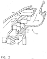
- Figure 2 is a schematic illustration of a blocker and swirl inducer hole 50 configuration in accordance with one embodiment of the present invention. More particularly, rather than injecting air into first swirl cavity 22, air is injected into second swirl cavity 52. In addition, blocker hole 50 is oriented to a 45-degree tangential angle with respect to the direction of rotation of seal 16, which results in pre-swirling the air before being injected into second swirl cavity 52. Further, the number of holes 50 is reduced by as much as 50% of the number of holes 30 ( Figure 1) used in the known CFM56 turbine.
- Blocker holes 50 therefore not only provide back-pressure, but also function as swirl-inducers. By inducing swirl into the air injected into second swirl cavity 52, better turbine disk rim cooling effectiveness is provided. This result facilitates maintaining reasonable metal temperatures at increasingly severe cycle conditions without the normally expected engine performance penalties.
- tangentially oriented holes 50 could open into first cavity 22 and still provide some benefits.
- swirl cavities can be formed between seal 16 and stationary components 14.
- three or more swirl cavities can be provided. If more than two swirl cavities are formed, the flow can be directed to a swirl cavity at the downstream end of the seal.
Landscapes
- Engineering & Computer Science (AREA)
- Mechanical Engineering (AREA)
- General Engineering & Computer Science (AREA)
- Turbine Rotor Nozzle Sealing (AREA)
Description
- This invention relates generally to gas turbine engines and more particularly, to a reducing the frictional heating of air passing through a forward outer seal in a high pressure turbine.
- Gas turbine engines generally include a high pressure compressor for compressing air flowing through the engine, a combustor in which fuel is mixed with the compressed air and ignited to form a high energy gas stream, and a high pressure turbine. The high pressure compressor, combustor and high pressure turbine sometimes are collectively referred to as the core engine. Such gas turbine engines also may include a low pressure compressor, or booster, for supplying compressed air, for further compression, to the high pressure compressor.
- If the disk rim temperature in the high pressure turbine approaches operational limits, rim cavity cooling systems are necessary. Low friction devices such as windage covers and straight or step-up seals have been used to control cooling temperatures and thereby protect critical components from increasingly severe engine cycle conditions. In addition, a combination of forward outer seal (FOS) flow and FOS bypass flow have been used to supply the forward rim cavity with reasonably cool air. The FOS bypass flow is effective because such flow is not affected by the friction heating in the seal. Such bypass flow, however, reduces performance of the high pressure turbine and high pressure turbine blade cooling flow.
- As performance targets become more aggressive, the FOS bypass flow must be reduced or eliminated. Of course, reducing or eliminating such flow should not adversely affect satisfying the cooling requirements.
- US-A-5281090 and US-A-4662821 each describe a cooling arrangement for a high pressure turbine using a plurality of blocker holes extending through a stationary component which receives a forward outer seal by pass flow and compressor discharge air with a swirl cavity between the stationary component and a rotating seal.
- According to the invention, there is provided a high pressure turbine comprising: a stationary component; a rotating seal; means for supplying cooling air for the seal, the cooling air being divided into a forward outer seal flow and a forward outer seal bypass flow; the rotating seal including at least first and second swirl cavities between said stationary component and said rotating seal, said second cavity being upstream from said first cavity with respect to the flow of the forward outer seal flow therebetween; and, characterised by: a plurality of blocker holes extending through said stationary component and opening into said second cavity so that an additional seal flow divided from the forward outer seal bypass flow is supplied to the second cavity during turbine operation, and wherein at least some of said blocker holes are tangentially oriented at an angle of about 45 degrees with respect to a direction of rotation of said seal. This arrangement results in pre-swirling the air before being injected into the swirl cavity. In addition, the number of holes is reduced by as much as 50% of the number of blocker holes used in the known CFM56 turbine. Further, rather than injecting the air into the first swirl cavity as is known, the air is injected into a second swirl cavity.
- The combined effect of orienting the holes to the 45-degree tangential angle with respect to the direction of rotation of the seal, locating the holes to open into the second swirl cavity, and reducing the flow area by about 50%, results in an increase in blocker hole pressure ratio. Increasing the blocker hole pressure ratio results in a higher hole exit velocity which maximizes the cavity inlet swirl.
- The above described blocker holes therefore not only provide back-pressure, but also function as swirl-inducers. By inducing swirl into the air injected into the second swirl cavity, better turbine disk rim cooling effectiveness is provided. This result facilitates maintaining reasonable metal temperatures at increasingly severe cycle conditions without the normally expected engine performance penalties.
- An embodiment of the invention will now be described, by way of example, with reference to the accompanying drawings, in which:-
- Figure 1 is a schematic illustration of a turbine disk rim including a known blocker hole configuration.
- Figure 2 is a schematic illustration of a turbine disk rim including a blocker and swirl inducer hole configuration in accordance with one embodiment of the present invention.
- The present invention is believed to be particularly useful in connection with high pressure turbines such as the CFM56 HP Turbine commercially available from General Electric Company, Cincinnati, Ohio. The present invention can, however, be utilized in connection with other high pressure turbines and is not limited to practice in the specific turbine configuration described below.
- More particularly, and referring to Figure 1 which is a schematic illustration of a portion of a
CFM56 turbine 10 including a known blocker hole configuration,turbine 10 includesrotating components 12 andstationary components 14 as is known. One of rotatingcomponents 12, for example, is aseal 16. A plurality of flow paths extend through at least portions ofturbine 10, such as a forward outer seal (FOS) flow 18 and aFOS bypass flow 20.Flow path 18 extends, for example, through a firstswirling cavity 22 betweenseal 16 andstationary components 14 to aforward rim cavity 24. Air is supplied toflow path 18 from both seal compressor delivery pressure (CDP)exit air 26 andnozzle cooling air 28. Air is supplied to FOS bypass flow from CDPseal exit air 26. - As shown in Figure 1, a
blocker hole 30 is formed instationary component 14, andseal exit air 26 flows throughblocker hole 30 into firstswirling cavity 22. Airflow throughblocker hole 30 provides back-pressure to seal 16 and limits the leakage of high pressure turbine blade cooling air throughseal 16. In practice, and in the CFM56 turbine, a plurality ofblocker holes 30 are provided. - Airflow through
blocker holes 30, however, results in injecting unswirled air into first swirlingcavity 22. As a result, rotatingseal 16 imparts more net torque on, and therefore more heat into, the cavity air. Injecting more heat into the cavity results in reducing the performance of the high pressure turbine and high pressure turbine blade cooling flow. - Figure 2 is a schematic illustration of a blocker and
swirl inducer hole 50 configuration in accordance with one embodiment of the present invention. More particularly, rather than injecting air intofirst swirl cavity 22, air is injected intosecond swirl cavity 52. In addition,blocker hole 50 is oriented to a 45-degree tangential angle with respect to the direction of rotation ofseal 16, which results in pre-swirling the air before being injected intosecond swirl cavity 52. Further, the number ofholes 50 is reduced by as much as 50% of the number of holes 30 (Figure 1) used in the known CFM56 turbine. - The combined effect of
orienting holes 50 to the 45-degree tangential angle with respect to the direction of rotation ofseal 16, locatingholes 50 to open intosecond swirl cavity 52, and reducing the flow area by about 50%, results in an increase in blocker hole pressure ratio. Increasing the blocker hole pressure ratio results in a higher hole exit velocity which maximizes the cavity inlet swirl. -
Blocker holes 50 therefore not only provide back-pressure, but also function as swirl-inducers. By inducing swirl into the air injected intosecond swirl cavity 52, better turbine disk rim cooling effectiveness is provided. This result facilitates maintaining reasonable metal temperatures at increasingly severe cycle conditions without the normally expected engine performance penalties. - In addition, rather than opening into
second cavity 52, tangentiallyoriented holes 50 could open intofirst cavity 22 and still provide some benefits. - In addition, more than two swirl cavities can be formed between
seal 16 andstationary components 14. For example, three or more swirl cavities can be provided. If more than two swirl cavities are formed, the flow can be directed to a swirl cavity at the downstream end of the seal.
Claims (4)
- A high pressure turbine (10) comprising:a stationary component (14);a rotating seal (16);means for supplying cooling air (26) for the seal, the cooling air being divided into a forward outer seal flow (18) and a forward outer seal bypass flow (20);the rotating seal (16) including at least first and second swirl cavities (22, 52) between said stationary component and said rotating seal, said second cavity being upstream from said first cavity with respect to the flow of the forward outer seal flow (18) therebetween; and, CHARACTERIZED BYa plurality of blocker holes (50) extending through said stationary component and opening into said second cavity (52) so that an additional seal flow divided from the forward outer seal bypass flow (20) is supplied to the second cavity during turbine operation, and wherein at least some of said blocker holes (50) are tangentially oriented at an angle of about 45 degrees with respect to a direction of rotation of said seal.
- The high pressure turbine in accordance with claim 1 wherein air flowing through said blocker holes is swirled as a result of flowing therethrough.
- The high pressure turbine in accordance with daim 1 wherein tangentially oriented blocker holes also open into said first cavity (22).
- The high pressure turbine in accordance with claim 1 wherein there is a stationary component outlet downstream from said blocker holes (50) whereby said remaining forward outer seal bypass flow is discharged into said forward outer seal flow (18) downstream from said rotating seal.
Applications Claiming Priority (2)
| Application Number | Priority Date | Filing Date | Title |
|---|---|---|---|
| US997833 | 1997-12-24 | ||
| US08/997,833 US5984630A (en) | 1997-12-24 | 1997-12-24 | Reduced windage high pressure turbine forward outer seal |
Publications (3)
| Publication Number | Publication Date |
|---|---|
| EP0926315A2 EP0926315A2 (en) | 1999-06-30 |
| EP0926315A3 EP0926315A3 (en) | 2000-08-23 |
| EP0926315B1 true EP0926315B1 (en) | 2005-09-21 |
Family
ID=25544452
Family Applications (1)
| Application Number | Title | Priority Date | Filing Date |
|---|---|---|---|
| EP98310389A Expired - Lifetime EP0926315B1 (en) | 1997-12-24 | 1998-12-17 | Turbine seal |
Country Status (4)
| Country | Link |
|---|---|
| US (1) | US5984630A (en) |
| EP (1) | EP0926315B1 (en) |
| JP (1) | JP4315504B2 (en) |
| DE (1) | DE69831646T2 (en) |
Families Citing this family (35)
| Publication number | Priority date | Publication date | Assignee | Title |
|---|---|---|---|---|
| US6095750A (en) * | 1998-12-21 | 2000-08-01 | General Electric Company | Turbine nozzle assembly |
| DE19916803A1 (en) * | 1999-04-14 | 2000-10-19 | Rolls Royce Deutschland | Hydraulic sealing arrangement, in particular on a gas turbine |
| DE19962244A1 (en) * | 1999-12-22 | 2001-06-28 | Rolls Royce Deutschland | Cooling air guide system in the high pressure turbine section of a gas turbine engine |
| US6761034B2 (en) * | 2000-12-08 | 2004-07-13 | General Electroc Company | Structural cover for gas turbine engine bolted flanges |
| US6773225B2 (en) | 2002-05-30 | 2004-08-10 | Mitsubishi Heavy Industries, Ltd. | Gas turbine and method of bleeding gas therefrom |
| FR2841591B1 (en) * | 2002-06-27 | 2006-01-13 | Snecma Moteurs | VENTILATION CIRCUITS OF THE TURBINE OF A TURBOMACHINE |
| US6749400B2 (en) | 2002-08-29 | 2004-06-15 | General Electric Company | Gas turbine engine disk rim with axially cutback and circumferentially skewed cooling air slots |
| GB0305974D0 (en) * | 2003-03-15 | 2003-04-23 | Rolls Royce Plc | A seal |
| DE10348290A1 (en) * | 2003-10-17 | 2005-05-12 | Mtu Aero Engines Gmbh | Sealing arrangement for a gas turbine |
| US7025565B2 (en) * | 2004-01-14 | 2006-04-11 | General Electric Company | Gas turbine engine component having bypass circuit |
| US7234918B2 (en) * | 2004-12-16 | 2007-06-26 | Siemens Power Generation, Inc. | Gap control system for turbine engines |
| GB2426289B (en) * | 2005-04-01 | 2007-07-04 | Rolls Royce Plc | Cooling system for a gas turbine engine |
| DE102005025244A1 (en) * | 2005-05-31 | 2006-12-07 | Rolls-Royce Deutschland Ltd & Co Kg | Air guiding system between compressor and turbine for gas-turbine engine operated at high pressure ratio has compressor and air chamber whereby first turbine cooling air is flowed through air chamber |
| GB0513468D0 (en) | 2005-07-01 | 2005-08-10 | Rolls Royce Plc | A mounting arrangement for turbine blades |
| CN101268284A (en) * | 2005-09-19 | 2008-09-17 | 英格索尔-兰德公司 | impeller of centrifugal compressor |
| EP1926915B1 (en) * | 2005-09-19 | 2016-12-28 | Ingersoll-Rand Company | Stationary seal ring for a centrifugal compressor |
| FR2891300A1 (en) * | 2005-09-23 | 2007-03-30 | Snecma Sa | DEVICE FOR CONTROLLING PLAY IN A GAS TURBINE |
| GB0620430D0 (en) | 2006-10-14 | 2006-11-22 | Rolls Royce Plc | A flow cavity arrangement |
| GB2477736B (en) * | 2010-02-10 | 2014-04-09 | Rolls Royce Plc | A seal arrangement |
| GB201013004D0 (en) * | 2010-08-03 | 2010-09-15 | Rolls Royce Plc | A seal assembly |
| GB201013003D0 (en) | 2010-08-03 | 2010-09-15 | Rolls Royce Plc | A seal assembly |
| US8529195B2 (en) | 2010-10-12 | 2013-09-10 | General Electric Company | Inducer for gas turbine system |
| US9175566B2 (en) * | 2012-09-26 | 2015-11-03 | Solar Turbines Incorporated | Gas turbine engine preswirler with angled holes |
| US9169729B2 (en) | 2012-09-26 | 2015-10-27 | Solar Turbines Incorporated | Gas turbine engine turbine diaphragm with angled holes |
| EP3047102B1 (en) | 2013-09-16 | 2020-05-06 | United Technologies Corporation | Gas turbine engine with disk having periphery with protrusions |
| US10301958B2 (en) | 2013-09-17 | 2019-05-28 | United Technologies Corporation | Gas turbine engine with seal having protrusions |
| EP3009613B1 (en) * | 2014-08-19 | 2019-01-30 | United Technologies Corporation | Contactless seals for gas turbine engines |
| US9810087B2 (en) | 2015-06-24 | 2017-11-07 | United Technologies Corporation | Reversible blade rotor seal with protrusions |
| US20170350265A1 (en) * | 2016-06-01 | 2017-12-07 | United Technologies Corporation | Flow metering and directing ring seal |
| FR3054606B1 (en) | 2016-07-29 | 2020-04-17 | Safran Aircraft Engines | TURBINE INCLUDING A VENTILATION SYSTEM BETWEEN ROTOR AND STATOR |
| FR3085405B1 (en) * | 2018-08-28 | 2020-12-04 | Safran Aircraft Engines | PRESSURIZATION OF THE INTER-LECHETTES CAVITY BY DERIVATION OF THE BYPASS FLOW |
| US11421597B2 (en) | 2019-10-18 | 2022-08-23 | Pratt & Whitney Canada Corp. | Tangential on-board injector (TOBI) assembly |
| CN112049689B (en) * | 2020-08-19 | 2021-06-18 | 西北工业大学 | High-position pre-rotation air supply system cover plate disc with staggered inclined blade type receiving holes |
| US11591911B2 (en) | 2021-04-23 | 2023-02-28 | Raytheon Technologies Corporation | Pressure gain for cooling flow in aircraft engines |
| CN114738119A (en) * | 2022-04-18 | 2022-07-12 | 中国航发沈阳发动机研究所 | Labyrinth sealing structure |
Family Cites Families (10)
| Publication number | Priority date | Publication date | Assignee | Title |
|---|---|---|---|---|
| GB995189A (en) * | 1963-11-04 | 1965-06-16 | Rolls Royce | Turbine |
| US3989410A (en) * | 1974-11-27 | 1976-11-02 | General Electric Company | Labyrinth seal system |
| US4466239A (en) * | 1983-02-22 | 1984-08-21 | General Electric Company | Gas turbine engine with improved air cooling circuit |
| US4513975A (en) * | 1984-04-27 | 1985-04-30 | General Electric Company | Thermally responsive labyrinth seal |
| FR2570763B1 (en) * | 1984-09-27 | 1986-11-28 | Snecma | DEVICE FOR AUTOMATICALLY CONTROLLING THE PLAY OF A TURBOMACHINE LABYRINTH SEAL |
| FR2570764B1 (en) * | 1984-09-27 | 1986-11-28 | Snecma | DEVICE FOR AUTOMATICALLY CONTROLLING THE PLAY OF A TURBOMACHINE LABYRINTH SEAL |
| US5281090A (en) * | 1990-04-03 | 1994-01-25 | General Electric Co. | Thermally-tuned rotary labyrinth seal with active seal clearance control |
| US5190440A (en) * | 1991-03-11 | 1993-03-02 | Dresser-Rand Company | Swirl control labyrinth seal |
| US5224713A (en) * | 1991-08-28 | 1993-07-06 | General Electric Company | Labyrinth seal with recirculating means for reducing or eliminating parasitic leakage through the seal |
| FR2712029B1 (en) * | 1993-11-03 | 1995-12-08 | Snecma | Turbomachine provided with a means for reheating the turbine disks when running at high speed. |
-
1997
- 1997-12-24 US US08/997,833 patent/US5984630A/en not_active Expired - Lifetime
-
1998
- 1998-12-16 JP JP35684198A patent/JP4315504B2/en not_active Expired - Fee Related
- 1998-12-17 EP EP98310389A patent/EP0926315B1/en not_active Expired - Lifetime
- 1998-12-17 DE DE69831646T patent/DE69831646T2/en not_active Expired - Lifetime
Also Published As
| Publication number | Publication date |
|---|---|
| EP0926315A3 (en) | 2000-08-23 |
| DE69831646D1 (en) | 2006-02-02 |
| EP0926315A2 (en) | 1999-06-30 |
| US5984630A (en) | 1999-11-16 |
| DE69831646T2 (en) | 2006-06-29 |
| JPH11236802A (en) | 1999-08-31 |
| JP4315504B2 (en) | 2009-08-19 |
Similar Documents
| Publication | Publication Date | Title |
|---|---|---|
| US5984630A (en) | Reduced windage high pressure turbine forward outer seal | |
| US8562285B2 (en) | Angled on-board injector | |
| US6735956B2 (en) | High pressure turbine blade cooling scoop | |
| US6276896B1 (en) | Apparatus and method for cooling Axi-Centrifugal impeller | |
| US6672072B1 (en) | Pressure boosted compressor cooling system | |
| US4462204A (en) | Gas turbine engine cooling airflow modulator | |
| US5374161A (en) | Blade outer air seal cooling enhanced with inter-segment film slot | |
| EP0348500B1 (en) | Annular combustor with tangential cooling air injection | |
| CA2519823C (en) | Methods and apparatus for assembling a gas turbine engine | |
| SE466464B (en) | TURBINE ENGINE WITH AIR AND COOLING AND SET FOR COOLING TURBINE ENGINE | |
| KR100537036B1 (en) | Centrifugal compressor | |
| WO1996013652A1 (en) | Gas turbine vane with enhanced cooling | |
| WO1994007005A1 (en) | Turbine vane assembly with integrally cast cooling fluid nozzle | |
| EP2702251A1 (en) | Casing cooling duct | |
| WO1994017285A1 (en) | Turbine vane having dedicated inner platform cooling | |
| US6401447B1 (en) | Combustor apparatus for a gas turbine engine | |
| EP1566524B1 (en) | Turbine casing cooling arrangement | |
| US7094020B2 (en) | Swirl-enhanced aerodynamic fastener shield for turbomachine | |
| GB2319308A (en) | Cooling gas turbine blades | |
| CN113123878B (en) | Variable area measurement with different α | |
| EP3012405B1 (en) | Gas turbine engine with coolant flow redirection component | |
| GB2345942A (en) | Gas turbine engine blade cooling air system | |
| US4265590A (en) | Cooling air supply arrangement for a gas turbine engine | |
| EP1217231B1 (en) | Bolted joint for rotor disks and method of reducing thermal gradients therein | |
| EP2045527B1 (en) | Faceted dome assemblies for gas turbine engine combustors |
Legal Events
| Date | Code | Title | Description |
|---|---|---|---|
| PUAI | Public reference made under article 153(3) epc to a published international application that has entered the european phase |
Free format text: ORIGINAL CODE: 0009012 |
|
| AK | Designated contracting states |
Kind code of ref document: A2 Designated state(s): DE FR GB IT |
|
| AX | Request for extension of the european patent |
Free format text: AL;LT;LV;MK;RO;SI |
|
| PUAL | Search report despatched |
Free format text: ORIGINAL CODE: 0009013 |
|
| AK | Designated contracting states |
Kind code of ref document: A3 Designated state(s): AT BE CH CY DE DK ES FI FR GB GR IE IT LI LU MC NL PT SE |
|
| AX | Request for extension of the european patent |
Free format text: AL;LT;LV;MK;RO;SI |
|
| 17P | Request for examination filed |
Effective date: 20010223 |
|
| AKX | Designation fees paid |
Free format text: DE FR GB IT |
|
| 17Q | First examination report despatched |
Effective date: 20021018 |
|
| GRAP | Despatch of communication of intention to grant a patent |
Free format text: ORIGINAL CODE: EPIDOSNIGR1 |
|
| GRAS | Grant fee paid |
Free format text: ORIGINAL CODE: EPIDOSNIGR3 |
|
| GRAA | (expected) grant |
Free format text: ORIGINAL CODE: 0009210 |
|
| AK | Designated contracting states |
Kind code of ref document: B1 Designated state(s): DE FR GB IT |
|
| REG | Reference to a national code |
Ref country code: GB Ref legal event code: FG4D |
|
| REF | Corresponds to: |
Ref document number: 69831646 Country of ref document: DE Date of ref document: 20051027 Kind code of ref document: P |
|
| REF | Corresponds to: |
Ref document number: 69831646 Country of ref document: DE Date of ref document: 20060202 Kind code of ref document: P |
|
| ET | Fr: translation filed | ||
| PLBE | No opposition filed within time limit |
Free format text: ORIGINAL CODE: 0009261 |
|
| STAA | Information on the status of an ep patent application or granted ep patent |
Free format text: STATUS: NO OPPOSITION FILED WITHIN TIME LIMIT |
|
| 26N | No opposition filed |
Effective date: 20060622 |
|
| REG | Reference to a national code |
Ref country code: FR Ref legal event code: PLFP Year of fee payment: 18 |
|
| PGFP | Annual fee paid to national office [announced via postgrant information from national office to epo] |
Ref country code: GB Payment date: 20151229 Year of fee payment: 18 |
|
| PGFP | Annual fee paid to national office [announced via postgrant information from national office to epo] |
Ref country code: FR Payment date: 20151217 Year of fee payment: 18 |
|
| PGFP | Annual fee paid to national office [announced via postgrant information from national office to epo] |
Ref country code: DE Payment date: 20151229 Year of fee payment: 18 |
|
| PG25 | Lapsed in a contracting state [announced via postgrant information from national office to epo] |
Ref country code: IT Free format text: LAPSE BECAUSE OF NON-PAYMENT OF DUE FEES Effective date: 20151217 |
|
| REG | Reference to a national code |
Ref country code: DE Ref legal event code: R119 Ref document number: 69831646 Country of ref document: DE |
|
| GBPC | Gb: european patent ceased through non-payment of renewal fee |
Effective date: 20161217 |
|
| PG25 | Lapsed in a contracting state [announced via postgrant information from national office to epo] |
Ref country code: IT Free format text: LAPSE BECAUSE OF NON-PAYMENT OF DUE FEES Effective date: 20151217 |
|
| PGFP | Annual fee paid to national office [announced via postgrant information from national office to epo] |
Ref country code: IT Payment date: 20151222 Year of fee payment: 18 |
|
| PGRI | Patent reinstated in contracting state [announced from national office to epo] |
Ref country code: IT Effective date: 20170710 |
|
| REG | Reference to a national code |
Ref country code: FR Ref legal event code: ST Effective date: 20170831 |
|
| PG25 | Lapsed in a contracting state [announced via postgrant information from national office to epo] |
Ref country code: FR Free format text: LAPSE BECAUSE OF NON-PAYMENT OF DUE FEES Effective date: 20170102 Ref country code: IT Free format text: LAPSE BECAUSE OF NON-PAYMENT OF DUE FEES Effective date: 20161217 |
|
| PGRI | Patent reinstated in contracting state [announced from national office to epo] |
Ref country code: IT Effective date: 20170710 |
|
| PG25 | Lapsed in a contracting state [announced via postgrant information from national office to epo] |
Ref country code: GB Free format text: LAPSE BECAUSE OF NON-PAYMENT OF DUE FEES Effective date: 20161217 Ref country code: DE Free format text: LAPSE BECAUSE OF NON-PAYMENT OF DUE FEES Effective date: 20170701 |