EP1566524B1 - Turbine casing cooling arrangement - Google Patents
Turbine casing cooling arrangement Download PDFInfo
- Publication number
- EP1566524B1 EP1566524B1 EP05250315.8A EP05250315A EP1566524B1 EP 1566524 B1 EP1566524 B1 EP 1566524B1 EP 05250315 A EP05250315 A EP 05250315A EP 1566524 B1 EP1566524 B1 EP 1566524B1
- Authority
- EP
- European Patent Office
- Prior art keywords
- casing
- arrangement
- fluid
- casing member
- heat transfer
- Prior art date
- Legal status (The legal status is an assumption and is not a legal conclusion. Google has not performed a legal analysis and makes no representation as to the accuracy of the status listed.)
- Ceased
Links
- 238000001816 cooling Methods 0.000 title description 9
- 239000012530 fluid Substances 0.000 claims description 49
- 239000013529 heat transfer fluid Substances 0.000 claims description 26
- 238000010438 heat treatment Methods 0.000 claims description 22
- 239000012809 cooling fluid Substances 0.000 claims description 11
- 238000011144 upstream manufacturing Methods 0.000 claims description 6
- 230000015572 biosynthetic process Effects 0.000 claims description 2
- 238000005755 formation reaction Methods 0.000 claims description 2
- 239000007789 gas Substances 0.000 description 15
- 239000000523 sample Substances 0.000 description 7
- 230000001141 propulsive effect Effects 0.000 description 3
- 230000004048 modification Effects 0.000 description 2
- 238000012986 modification Methods 0.000 description 2
- 238000002485 combustion reaction Methods 0.000 description 1
- 230000006835 compression Effects 0.000 description 1
- 238000007906 compression Methods 0.000 description 1
- 230000003247 decreasing effect Effects 0.000 description 1
- 239000000446 fuel Substances 0.000 description 1
- 239000000203 mixture Substances 0.000 description 1
Images


Classifications
-
- F—MECHANICAL ENGINEERING; LIGHTING; HEATING; WEAPONS; BLASTING
- F01—MACHINES OR ENGINES IN GENERAL; ENGINE PLANTS IN GENERAL; STEAM ENGINES
- F01D—NON-POSITIVE DISPLACEMENT MACHINES OR ENGINES, e.g. STEAM TURBINES
- F01D25/00—Component parts, details, or accessories, not provided for in, or of interest apart from, other groups
- F01D25/08—Cooling; Heating; Heat-insulation
- F01D25/14—Casings modified therefor
-
- F—MECHANICAL ENGINEERING; LIGHTING; HEATING; WEAPONS; BLASTING
- F01—MACHINES OR ENGINES IN GENERAL; ENGINE PLANTS IN GENERAL; STEAM ENGINES
- F01D—NON-POSITIVE DISPLACEMENT MACHINES OR ENGINES, e.g. STEAM TURBINES
- F01D25/00—Component parts, details, or accessories, not provided for in, or of interest apart from, other groups
- F01D25/24—Casings; Casing parts, e.g. diaphragms, casing fastenings
- F01D25/243—Flange connections; Bolting arrangements
-
- F—MECHANICAL ENGINEERING; LIGHTING; HEATING; WEAPONS; BLASTING
- F05—INDEXING SCHEMES RELATING TO ENGINES OR PUMPS IN VARIOUS SUBCLASSES OF CLASSES F01-F04
- F05D—INDEXING SCHEME FOR ASPECTS RELATING TO NON-POSITIVE-DISPLACEMENT MACHINES OR ENGINES, GAS-TURBINES OR JET-PROPULSION PLANTS
- F05D2240/00—Components
- F05D2240/10—Stators
- F05D2240/11—Shroud seal segments
-
- F—MECHANICAL ENGINEERING; LIGHTING; HEATING; WEAPONS; BLASTING
- F05—INDEXING SCHEMES RELATING TO ENGINES OR PUMPS IN VARIOUS SUBCLASSES OF CLASSES F01-F04
- F05D—INDEXING SCHEME FOR ASPECTS RELATING TO NON-POSITIVE-DISPLACEMENT MACHINES OR ENGINES, GAS-TURBINES OR JET-PROPULSION PLANTS
- F05D2260/00—Function
- F05D2260/20—Heat transfer, e.g. cooling
- F05D2260/205—Cooling fluid recirculation, i.e. after cooling one or more components is the cooling fluid recovered and used elsewhere for other purposes
-
- Y—GENERAL TAGGING OF NEW TECHNOLOGICAL DEVELOPMENTS; GENERAL TAGGING OF CROSS-SECTIONAL TECHNOLOGIES SPANNING OVER SEVERAL SECTIONS OF THE IPC; TECHNICAL SUBJECTS COVERED BY FORMER USPC CROSS-REFERENCE ART COLLECTIONS [XRACs] AND DIGESTS
- Y02—TECHNOLOGIES OR APPLICATIONS FOR MITIGATION OR ADAPTATION AGAINST CLIMATE CHANGE
- Y02T—CLIMATE CHANGE MITIGATION TECHNOLOGIES RELATED TO TRANSPORTATION
- Y02T50/00—Aeronautics or air transport
- Y02T50/60—Efficient propulsion technologies, e.g. for aircraft
Definitions
- a casing arrangement for surrounding a rotary component of a gas turbine in accordance with the features of claim 1, the casing arrangement comprising a casing member formed to extend at least partially around the component, wherein the casing member defines a fluid flow path for the flow of a heat transfer fluid therethrough, said arrangement additionally comprising a control device to control the rate of flow of heat transfer fluid through said defined fluid flow path and hence the extent of thermal expansion of said casing member.
- the casing member defines a plurality of said paths, which extend generally parallel to one another.
- The, or each, path extend from an upstream region to a downstream region of the casing member.
- the flow of said heat transfer fluid may be from the upstream region of the casing member to the downstream region thereof.
- a seal segment may be provided on the casing member.
- the casing member may include formations to mount the seal segment inwardly of the casing member.
- the seal segment may be arranged between the casing member and the rotary component.
- the seal segment may define a fluid flow passage and the fluid flow path in the casing member may communicate with the fluid flow passage.
- the heat transfer fluid may be a cooling fluid and/or a heating fluid.
- the control device may select a flow of heating fluid and/or a flow of cooling fluid, as circumstances dictate.
- the control device may be connected, for example, electrically connected to a cooling fluid feed assembly to control the rate of flow of cooling fluid through the or each fluid flow path.
- the control device may be connected, for example, electrically connected to a heating feed assembly to control the rate of flow of heating fluid through the or each, flow path.
- the passage may be communicatively connected to the heat transfer fluid flow path.
- a chamber is arranged between the casing member and the seal segments whereby at least some of the heat transfer fluid exiting from the heat transfer fluid flow path enters the chamber. Heat transfer fluid from the chamber may enter the passage through the seal segment to provide cooling or heating to the seal segment.
- control device controls the flow of the heat transfer fluid through the casing member such that the flow rate through the heat transfer fluid flow path is so arranged that the thermal response of the casing member matches the radial dimensional variation of the rotary component surrounded thereby.
- the cooling fluid may be air provided from a cooler region of the engine, preferable from by-pass air driven by the fan.
- the cooling air may be provided from air driven by the compressors of the engine.
- the heating fluid may be provided as gas taken from high temperature regions of the engine, e.g. the low pressure turbine.
- the heating fluid may be provided by a heating device e.g. an electrical heater.
- the gas turbine engine 10 operates in a conventional manner so that air entering the intake 11 is accelerated by the fan 12 which produce two air flows: a first air flow into the intermediate pressure compressor 13 and a second air flow which provides propulsive thrust.
- the intermediate pressure compressor compresses the airflow directed into it before delivering that air to the high-pressure compressor 14 where further compression takes place.
- FIG. 2 and 3 there is shown a circumferential sectional side view of a casing arrangement 20 encasing the high-pressure turbine 16.
- the high-pressure turbine 16 has a plurality of radially outwardly extending turbine blades 116 mounted on a disc (not shown).
- the casing arrangement 20 comprises a plurality of interconnected casing members, only some of which, namely casing members 22A, 22B, 22C are shown. Other casing members may be provided, as will be appreciated by a person skilled in the art, but these are not shown in Fig. 2 .
- the main casing member 22A in Fig. 2 defines a plurality of fluid flow paths 24 for the flow of a heat transfer fluid therethrough. As can be seen from Fig. 3 , the heat transfer fluid flow paths 24 are arranged adjacent one another circumferentially around the high-pressure turbine blades 116.
- the fluid flow paths 24 extend in an axial direction from an upstream region A of the turbine 16 to a downstream region B.
- the heat transfer fluid flowing along the fluid flow paths 24 can be a cooling fluid or a heating fluid, or both, to control the gap or tip clearance 30 between the radially outer edges of the turbine blades 116 and seal segments 28 surrounding the turbine blades 116, as explained below.
- a plurality of circumferentially extending seal segments 28 are arranged radially inwardly of the casing member 22B to provide a seal with the turbine blades 116.
- a gap or tip clearance 30 is defined between the radially outer edges of the turbine blades 116 and the radially inner surface of the seal segments. It is desirable to maintain the tip clearance 30 at the required distance to minimise leakage of air across the tips of the turbine blades 116.
- a measuring device or probe 32 is provided on the seal segments 28.
- the probe 32 measures the tip clearance 30 between the tips of the blades 116 and the radially inner surface of the seal 28.
- the probe 32 is electrically connected to a valve shown schematically at 34 in a conduit 36 (also shown schematically) that directs the cooling fluid through the aperture 26 to the fluid flow paths 24.
- the probe 32 directs the valve 34 to open further thereby allowing more and more cooling air to flow through the fluid flow paths 24 to limit or reduce the expansion of the casing 20, thereby reducing the tip clearance 30, or decreasing the rate of increase of the tip clearance 30.
- the probe 32 which is also electrically connected to a valve, shown schematically at 38 in a conduit 40 (also shown schematically).
- the conduit 36 directs the heating fluid through the aperture 26 to the fluid flow paths 24, to increase the tip clearance 30.
- the heating fluid can be provided from a turbine e.g. the low pressure turbine 18 and/or from an electrical heating device 42 shown schematically in Fig. 2 in broken lines.
- FIG. 4 there is shown a further embodiment, which comprises many of the same features as shown in Fig. 2 , i.e. a casing 120 which extends circumferentially around the turbine blades 116.
- the casing 120 comprises a plurality of casing members 122A, 122B, 122C.
- a seal segment 128 is mounted on the casing members 122A, 122B and provides a seal against the radially outer tip of the turbine blade 116, in the same way as for the embodiment shown in Fig. 2 .
- the casing members 122A, 122B define a fluid flow path 124A, 124B.
- the fluid flow path 124A, 124B receives heat transfer fluid from the compressors 13, 14, as shown by the arrows Y, or from the turbines or other suitable heating device 42 (see Fig. 2 ).
- the heating fluid enters at an upstream region A and travels to a downstream region B of the fluid flow path 124A, 124B.
- the heat transfer splits into two streams.
- the first stream, designated Y1 passes out of the casing arrangement 20 and can then be passed to exhaust.
- the second stream, labelled Y2 passes into a main circumferential chamber 126 provided between the casing member 122A and the seal segment 128.
- the second stream Y2 of the heat transfer fluid then passes from the main circumferential chamber 126 into a heat transfer path 134 in the seal segment 128, thereby providing heat transfer for the seal segment 128.
- the seal segment 28 is provided with a probe 132, similar to the probe 32 shown in Fig. 2 and this is electrically connected to valves (not shown in Fig. 4 ) for controlling the rate of flow of heat transfer fluid from the compressor, turbine or heating device to the fluid flow path 124A, 124B.
- the embodiment shown in Fig. 4 operates in a similar way to that shown in Fig. 2 , in that heat transfer fluid in the form of gas flows through the fluid flow path 124A, 124B to the extent of expansion of the casing 120, thereby controlling the tip clearance 30.
- a further modification is shown in Fig. 5 , which is almost the same as the embodiment shown in Fig. 4 and the same features have been designated with the same reference numerals.
- the embodiment shown in Fig. 4 differs from the embodiment shown in Fig.
- the first part 124A of the fluid flow path directs the heat transfer fluid into a preliminary circumferentially extending chamber 127, and thereafter, the heat transfer fluid passes into the second part 124B of the fluid flow path to the downstream region B where it separates into two streams Y1, Y2.
- the stream designated Y2 passes into the main circumferential chamber 126 and thereafter into the fluid flow path 134 of the seal segment 128.
- casing arrangement 20 for a gas turbine engine 10 which allows heat transfer fluid to be passed therethrough to enable the expansion of the casing arrangement 20 to be controlled, and restricted thereby controlling the gap between the tips of the turbine blades 115 and the seal segments 28.
Landscapes
- Engineering & Computer Science (AREA)
- Mechanical Engineering (AREA)
- General Engineering & Computer Science (AREA)
- Turbine Rotor Nozzle Sealing (AREA)
Description
- This invention relates to casing arrangements. More particularly, but not exclusively, the invention relates to casing arrangements for surrounding rotary components of gas turbine engines, such as turbines.
- In high-pressure turbines of gas turbine engines, it is necessary to ensure that there is a minimum clearance between the tip of the turbine blades and the casing surrounding the blades. However, during turbine operation, the temperature of the gases passing through the turbine causes the casing to expand thereby increasing the gap between the tip of the blades and the casing.
- It is known, for instance from
EP 0 877 149 , to provide a gas turbine engine in which a casing that surrounds an array of turbine blades is itself surrounded by a manifold that directs cooling air on to the casing. The cooling air so directed causes the casing to thermally contract, so minimising the clearance between the casing and the tips of the blades that it surrounds. While such arrangements can be useful in ensuring that blade tip clearances are minimised, they do result in the provision of equipment on the external surface of the casing. Such equipment adds weight and can be undesirable if, for instance, the gas turbine engine in question is situated in a confined space or is of small size. -
JP 09-032580 - It is an object of the present invention to provide an improved cooled casing arrangement that is more compact than is the case with arrangements employing externally located cooling air manifold systems.
- According to one aspect of this invention, there is provided a casing arrangement for surrounding a rotary component of a gas turbine in accordance with the features of claim 1, the casing arrangement comprising a casing member formed to extend at least partially around the component, wherein the casing member defines a fluid flow path for the flow of a heat transfer fluid therethrough, said arrangement additionally comprising a control device to control the rate of flow of heat transfer fluid through said defined fluid flow path and hence the extent of thermal expansion of said casing member.
- The casing member defines a plurality of said paths, which extend generally parallel to one another. The, or each, path extend from an upstream region to a downstream region of the casing member.
- Each fluid flow path may be extendible axially of the engine. The fluid flow paths may be arranged circumferentially adjacent each other around the engine.
- The flow of said heat transfer fluid may be from the upstream region of the casing member to the downstream region thereof.
- In one embodiment, a seal segment may be provided on the casing member. The casing member may include formations to mount the seal segment inwardly of the casing member. In this embodiment, the seal segment may be arranged between the casing member and the rotary component. The seal segment may define a fluid flow passage and the fluid flow path in the casing member may communicate with the fluid flow passage.
- The casing arrangement may comprise a control device arranged to determine the distance between the rotary component and the casing arrangement. The control device may be disposed either on the casing member or on the seal segment between the casing arrangement and the rotary component.
- The heat transfer fluid may be a cooling fluid and/or a heating fluid. In one embodiment, the control device may select a flow of heating fluid and/or a flow of cooling fluid, as circumstances dictate.
- The control device may be connected, for example, electrically connected to a cooling fluid feed assembly to control the rate of flow of cooling fluid through the or each fluid flow path. The control device may be connected, for example, electrically connected to a heating feed assembly to control the rate of flow of heating fluid through the or each, flow path.
- The passage may be communicatively connected to the heat transfer fluid flow path. Preferably, a chamber is arranged between the casing member and the seal segments whereby at least some of the heat transfer fluid exiting from the heat transfer fluid flow path enters the chamber. Heat transfer fluid from the chamber may enter the passage through the seal segment to provide cooling or heating to the seal segment.
- Preferably, the control device controls the flow of the heat transfer fluid through the casing member such that the flow rate through the heat transfer fluid flow path is so arranged that the thermal response of the casing member matches the radial dimensional variation of the rotary component surrounded thereby.
- In one embodiment, where the gas turbine engine includes a fan, the cooling fluid may be air provided from a cooler region of the engine, preferable from by-pass air driven by the fan. In another embodiment, the cooling air may be provided from air driven by the compressors of the engine. The heating fluid may be provided as gas taken from high temperature regions of the engine, e.g. the low pressure turbine. Alternatively, the heating fluid may be provided by a heating device e.g. an electrical heater.
- Embodiments of the invention will now be described by way of example only, with reference to the accompanying drawings, in which:-
-
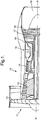
Fig. 1 is a sectional side view of the upper half of a gas turbine engine; -
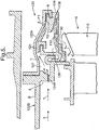
Fig. 2 is a sectional side view of a first embodiment of a casing arrangement; -
Fig. 3 is a view along the lines III-III ofFig. 2 ; -
Fig. 4 is a sectional side view of a second embodiment of a casing arrangement; and -
Fig. 5 is a sectional side view of a third embodiment of a casing arrangement. - Referring to
Fig. 1 , a gas turbine engine is generally indicated at 10 and comprises, in axial flow series, anair intake 11, apropulsive fan 12, anintermediate pressure compressor 13, ahigh pressure compressor 14, acombustor 15, a turbine arrangement comprising ahigh pressure turbine 16, anintermediate pressure turbine 17 and alow pressure turbine 18, and anexhaust nozzle 19. - The
gas turbine engine 10 operates in a conventional manner so that air entering theintake 11 is accelerated by thefan 12 which produce two air flows: a first air flow into theintermediate pressure compressor 13 and a second air flow which provides propulsive thrust. The intermediate pressure compressor compresses the airflow directed into it before delivering that air to the high-pressure compressor 14 where further compression takes place. - The compressed air exhausted from the high-
pressure compressor 14 is directed into thecombustor 15 where it is mixed with fuel and the mixture combusted. The resultant hot combustion products then expand through, and thereby drive, the high, intermediate and low-pressure turbines nozzle 19 to provide additional propulsive thrust. The high, intermediate and low-pressure turbines intermediate pressure compressors fan 12 by suitable interconnecting shafts. - Referring to
Figs. 2 and 3 there is shown a circumferential sectional side view of acasing arrangement 20 encasing the high-pressure turbine 16. The high-pressure turbine 16 has a plurality of radially outwardly extendingturbine blades 116 mounted on a disc (not shown). Thecasing arrangement 20 comprises a plurality of interconnected casing members, only some of which, namelycasing members Fig. 2 . - The
main casing member 22A inFig. 2 defines a plurality offluid flow paths 24 for the flow of a heat transfer fluid therethrough. As can be seen fromFig. 3 , the heat transferfluid flow paths 24 are arranged adjacent one another circumferentially around the high-pressure turbine blades 116. - The
fluid flow paths 24 extend in an axial direction from an upstream region A of theturbine 16 to a downstream region B. - The heat transfer fluid flowing along the
fluid flow paths 24 can be a cooling fluid or a heating fluid, or both, to control the gap ortip clearance 30 between the radially outer edges of theturbine blades 116 andseal segments 28 surrounding theturbine blades 116, as explained below. - In order to supply a cooling fluid to the
fluid flow paths 24, at least some of the air from thefan 12, which by-passes thecompressors turbines casing member 22A via anaperture 26, and thereafter passes into thefluid flow paths 24 at the upstream region A to exit therefrom at the downstream region B, as shown by the arrows X. - A plurality of circumferentially extending
seal segments 28 are arranged radially inwardly of thecasing member 22B to provide a seal with theturbine blades 116. A gap ortip clearance 30 is defined between the radially outer edges of theturbine blades 116 and the radially inner surface of the seal segments. It is desirable to maintain thetip clearance 30 at the required distance to minimise leakage of air across the tips of theturbine blades 116. - During operation of the
turbine 16, the hot gases can cause thecasing arrangement 20 to expand, thereby increasing the size of thetip clearance 30. The flow of cooling air through thefluid flow path 24 minimises the extent of this expansion. - In order to control the level of expansion of the
casing 20, a measuring device orprobe 32 is provided on theseal segments 28. Theprobe 32 measures thetip clearance 30 between the tips of theblades 116 and the radially inner surface of theseal 28. Theprobe 32 is electrically connected to a valve shown schematically at 34 in a conduit 36 (also shown schematically) that directs the cooling fluid through theaperture 26 to thefluid flow paths 24. As thetip clearance 30 increases, theprobe 32 directs thevalve 34 to open further thereby allowing more and more cooling air to flow through thefluid flow paths 24 to limit or reduce the expansion of thecasing 20, thereby reducing thetip clearance 30, or decreasing the rate of increase of thetip clearance 30. - In certain circumstances, it may be necessary to supply heating air through the
fluid flow paths 24 to control the tip clearance. In such circumstances, theprobe 32, which is also electrically connected to a valve, shown schematically at 38 in a conduit 40 (also shown schematically). Theconduit 36 directs the heating fluid through theaperture 26 to thefluid flow paths 24, to increase thetip clearance 30. Thus, by the use of the cooling and heating fluids as described above thetip clearance 30 can be precisely controlled. - The heating fluid can be provided from a turbine e.g. the
low pressure turbine 18 and/or from anelectrical heating device 42 shown schematically inFig. 2 in broken lines. - Referring to
Fig. 4 , there is shown a further embodiment, which comprises many of the same features as shown inFig. 2 , i.e. acasing 120 which extends circumferentially around theturbine blades 116. Thecasing 120 comprises a plurality ofcasing members seal segment 128 is mounted on thecasing members turbine blade 116, in the same way as for the embodiment shown inFig. 2 . - The
casing members fluid flow path fluid flow path compressors Fig. 2 ). The heating fluid enters at an upstream region A and travels to a downstream region B of thefluid flow path casing arrangement 20 and can then be passed to exhaust. The second stream, labelled Y2, passes into a maincircumferential chamber 126 provided between the casingmember 122A and theseal segment 128. The second stream Y2 of the heat transfer fluid then passes from the maincircumferential chamber 126 into aheat transfer path 134 in theseal segment 128, thereby providing heat transfer for theseal segment 128. - As shown in
Fig. 4 , theseal segment 28 is provided with aprobe 132, similar to theprobe 32 shown inFig. 2 and this is electrically connected to valves (not shown inFig. 4 ) for controlling the rate of flow of heat transfer fluid from the compressor, turbine or heating device to thefluid flow path - In operation, the embodiment shown in
Fig. 4 operates in a similar way to that shown inFig. 2 , in that heat transfer fluid in the form of gas flows through thefluid flow path casing 120, thereby controlling thetip clearance 30. A further modification is shown inFig. 5 , which is almost the same as the embodiment shown inFig. 4 and the same features have been designated with the same reference numerals. The embodiment shown inFig. 4 differs from the embodiment shown inFig. 4 in that thefirst part 124A of the fluid flow path directs the heat transfer fluid into a preliminarycircumferentially extending chamber 127, and thereafter, the heat transfer fluid passes into thesecond part 124B of the fluid flow path to the downstream region B where it separates into two streams Y1, Y2. The stream designated Y2 passes into the maincircumferential chamber 126 and thereafter into thefluid flow path 134 of theseal segment 128. - There is thus described a
casing arrangement 20 for agas turbine engine 10 which allows heat transfer fluid to be passed therethrough to enable the expansion of thecasing arrangement 20 to be controlled, and restricted thereby controlling the gap between the tips of the turbine blades 115 and theseal segments 28. - Various modifications can be made without departing from the scope of the invention. For example, the arrangement of casing members can be varied.
Claims (16)
- A casing arrangement (20) for surrounding a rotary component (16) of a gas turbine engine (10), the casing arrangement (20) comprising a casing member (22A) formed to extend at least partially around the component (116)), wherein the casing member (22A) defines a fluid flow path (24) for the flow of a heat transfer fluid therethrough, and wherein said arrangement additionally comprises a control device (34) to control the rate of flow of heat transfer fluid through said defined fluid flow path (24) and hence the extent of thermal expansion of said casing member (22A);
characterised in that the casing member (22A) defines a plurality of said paths (24) which extend generally parallel to one another, said paths (24) extending from an upstream region to a downstream region of the casing member (22A). - A casing arrangement (20) according to claim 1 characterised in that the fluid flow paths (24) are arranged to extend axially of the engine (10) and are positioned circumferentially adjacent one another around the engine (10).
- A casing arrangement (20) according to any preceding claim, characterised in that the casing member (22A) includes formations to mount a seal segment (28) inwardly of the casing member (22A), whereby the seal segment (28) is positioned between the casing member (22A) and the rotary component (116).
- A casing arrangement (20) according to claim 3, characterised in that the seal segment (28) defines at least one fluid flow passage (134) and the, or each, fluid flow path in the casing member (124A,124B) communicates with the, each, or a respective, fluid flow passage (134) in the seal segment.
- A casing arrangement (20) according to claim 4, characterised in that a chamber (126) is arranged between the casing member (122A) and the seal segment (128) such that at least some of the heat transfer fluid exiting from the fluid flow path (124A,124B) enters the chamber (126), and fluid from the chamber (126) enters the fluid flow passage (134) in the seal segment (128) to provide heat transfer at the seal segment (128).
- A casing arrangement (20) according to any preceding claim characterised in that such arrangement comprises a control device (132) arranged to determine the distance between the rotary component (116) and the seal segment (128).
- A casing arrangement (20) according to claim 6, characterised in that the control device (34) is disposed either on the casing member (124A,124B) or on the seal segment (128).
- A casing arrangement (20) according to claim 6 or 7, characterised in that the control device (34) controls the flow of fluid through the casing member (124A,124B) such that the thermal response of the casing member (124A,124B) matches the radial dimensional variation of the rotary component (116) encased thereby.
- A casing arrangement (20) according to any preceding claim, characterised in that the heat transfer fluid comprises cooling fluid.
- A casing arrangement (20) as claimed in claim 9, characterised in that the gas turbine engine (10) includes a fan (12) and the cooling fluid comprises air provided from by-pass air driven by the fan (12).
- A casing arrangement (20) according to claims 9 or 10, characterised in that the cooling fluid is air provided from air driven by the compressors (13,14) of the engine (10).
- A casing arrangement according to any preceding claim characterised in that the heat transfer fluid comprises heating fluid.
- A casing arrangement (20) according to claim 12 characterised in that the heating fluid is provided from a turbine of the gas turbine engine (10).
- A casing arrangement (20) according to claim 12 or 13 characterised in that said arrangement comprises a heating device (42) for heating the heat transfer fluid to provide the heating fluid.
- A turbine arrangement incorporating a casing arrangement as claimed in any preceding claim.
- A gas turbine engine incorporating a turbine arrangement as claimed in claim 15.
Applications Claiming Priority (2)
| Application Number | Priority Date | Filing Date | Title |
|---|---|---|---|
| GBGB0403198.5A GB0403198D0 (en) | 2004-02-13 | 2004-02-13 | Casing arrangement |
| GB0403198 | 2004-02-13 |
Publications (3)
| Publication Number | Publication Date |
|---|---|
| EP1566524A2 EP1566524A2 (en) | 2005-08-24 |
| EP1566524A3 EP1566524A3 (en) | 2013-05-01 |
| EP1566524B1 true EP1566524B1 (en) | 2018-05-16 |
Family
ID=32011844
Family Applications (1)
| Application Number | Title | Priority Date | Filing Date |
|---|---|---|---|
| EP05250315.8A Ceased EP1566524B1 (en) | 2004-02-13 | 2005-01-21 | Turbine casing cooling arrangement |
Country Status (4)
| Country | Link |
|---|---|
| US (1) | US7347661B2 (en) |
| EP (1) | EP1566524B1 (en) |
| JP (1) | JP4791048B2 (en) |
| GB (1) | GB0403198D0 (en) |
Families Citing this family (19)
| Publication number | Priority date | Publication date | Assignee | Title |
|---|---|---|---|---|
| US8616827B2 (en) | 2008-02-20 | 2013-12-31 | Rolls-Royce Corporation | Turbine blade tip clearance system |
| US8256228B2 (en) * | 2008-04-29 | 2012-09-04 | Rolls Royce Corporation | Turbine blade tip clearance apparatus and method |
| FR2931197B1 (en) * | 2008-05-16 | 2010-06-18 | Snecma | LOCKING SECTOR OF RING SECTIONS ON A TURBOMACHINE CASING, COMPRISING AXIAL PASSAGES FOR ITS PRETENSION |
| US8092153B2 (en) * | 2008-12-16 | 2012-01-10 | Pratt & Whitney Canada Corp. | Bypass air scoop for gas turbine engine |
| US8186933B2 (en) * | 2009-03-24 | 2012-05-29 | General Electric Company | Systems, methods, and apparatus for passive purge flow control in a turbine |
| JP5367497B2 (en) * | 2009-08-07 | 2013-12-11 | 株式会社東芝 | Steam turbine |
| US8662824B2 (en) * | 2010-01-28 | 2014-03-04 | Pratt & Whitney Canada Corp. | Rotor containment structure for gas turbine engine |
| JP5791232B2 (en) * | 2010-02-24 | 2015-10-07 | 三菱重工航空エンジン株式会社 | Aviation gas turbine |
| GB201004381D0 (en) * | 2010-03-17 | 2010-04-28 | Rolls Royce Plc | Rotor blade tip clearance control |
| CH704124A1 (en) * | 2010-11-19 | 2012-05-31 | Alstom Technology Ltd | Rotating machine, in particular gas turbine. |
| US8899051B2 (en) * | 2010-12-30 | 2014-12-02 | Rolls-Royce Corporation | Gas turbine engine flange assembly including flow circuit |
| WO2014130159A1 (en) | 2013-02-23 | 2014-08-28 | Ottow Nathan W | Blade clearance control for gas turbine engine |
| RU2538985C1 (en) * | 2013-12-30 | 2015-01-10 | Открытое акционерное общество "Авиадвигатель" | High-temperature turbine stator |
| EP3040518B1 (en) | 2014-12-16 | 2017-04-26 | Rolls-Royce plc | Tip clearance control for turbine blades |
| EP3040519B1 (en) * | 2014-12-16 | 2017-04-26 | Rolls-Royce plc | Tip clearance control for turbine blades |
| US10975721B2 (en) | 2016-01-12 | 2021-04-13 | Pratt & Whitney Canada Corp. | Cooled containment case using internal plenum |
| US10415420B2 (en) * | 2016-04-08 | 2019-09-17 | United Technologies Corporation | Thermal lifting member for blade outer air seal support |
| GB201708744D0 (en) * | 2017-06-01 | 2017-07-19 | Rolls Royce Plc | Clearance control arrangement |
| US10704408B2 (en) * | 2018-05-03 | 2020-07-07 | Rolls-Royce North American Technologies Inc. | Dual response blade track system |
Citations (4)
| Publication number | Priority date | Publication date | Assignee | Title |
|---|---|---|---|---|
| US4023919A (en) * | 1974-12-19 | 1977-05-17 | General Electric Company | Thermal actuated valve for clearance control |
| US4386885A (en) * | 1980-05-19 | 1983-06-07 | Bbc Brown Boveri & Company Limited | Cooled guide support vane |
| JPH0932580A (en) * | 1995-07-12 | 1997-02-04 | Mitsubishi Heavy Ind Ltd | Gas turbine blade tip clearance control device |
| US5779436A (en) * | 1996-08-07 | 1998-07-14 | Solar Turbines Incorporated | Turbine blade clearance control system |
Family Cites Families (8)
| Publication number | Priority date | Publication date | Assignee | Title |
|---|---|---|---|---|
| US3966354A (en) * | 1974-12-19 | 1976-06-29 | General Electric Company | Thermal actuated valve for clearance control |
| JPS5857100A (en) | 1981-09-30 | 1983-04-05 | Hitachi Ltd | Blade-tip clearance adjustment type axial-flow compressor |
| US4643638A (en) * | 1983-12-21 | 1987-02-17 | United Technologies Corporation | Stator structure for supporting an outer air seal in a gas turbine engine |
| JPH06101418A (en) * | 1992-09-18 | 1994-04-12 | Toshiba Corp | Steam turbine casing temperature adjusting device |
| JPH108911A (en) * | 1996-06-19 | 1998-01-13 | Ishikawajima Harima Heavy Ind Co Ltd | Double shell turbine casing |
| GB9709086D0 (en) | 1997-05-07 | 1997-06-25 | Rolls Royce Plc | Gas turbine engine cooling apparatus |
| JP3631898B2 (en) * | 1998-03-03 | 2005-03-23 | 三菱重工業株式会社 | Cooling structure of split ring in gas turbine |
| JP2005042612A (en) * | 2003-07-22 | 2005-02-17 | Ishikawajima Harima Heavy Ind Co Ltd | Casing, casing deformation prevention system and method |
-
2004
- 2004-02-13 GB GBGB0403198.5A patent/GB0403198D0/en not_active Ceased
-
2005
- 2005-01-21 EP EP05250315.8A patent/EP1566524B1/en not_active Ceased
- 2005-01-25 US US11/041,451 patent/US7347661B2/en not_active Expired - Lifetime
- 2005-02-14 JP JP2005035671A patent/JP4791048B2/en not_active Expired - Fee Related
Patent Citations (4)
| Publication number | Priority date | Publication date | Assignee | Title |
|---|---|---|---|---|
| US4023919A (en) * | 1974-12-19 | 1977-05-17 | General Electric Company | Thermal actuated valve for clearance control |
| US4386885A (en) * | 1980-05-19 | 1983-06-07 | Bbc Brown Boveri & Company Limited | Cooled guide support vane |
| JPH0932580A (en) * | 1995-07-12 | 1997-02-04 | Mitsubishi Heavy Ind Ltd | Gas turbine blade tip clearance control device |
| US5779436A (en) * | 1996-08-07 | 1998-07-14 | Solar Turbines Incorporated | Turbine blade clearance control system |
Also Published As
| Publication number | Publication date |
|---|---|
| EP1566524A3 (en) | 2013-05-01 |
| GB0403198D0 (en) | 2004-03-17 |
| US20050238480A1 (en) | 2005-10-27 |
| EP1566524A2 (en) | 2005-08-24 |
| JP4791048B2 (en) | 2011-10-12 |
| US7347661B2 (en) | 2008-03-25 |
| JP2005226653A (en) | 2005-08-25 |
Similar Documents
| Publication | Publication Date | Title |
|---|---|---|
| EP1566524B1 (en) | Turbine casing cooling arrangement | |
| US5297386A (en) | Cooling system for a gas turbine engine compressor | |
| US7383686B2 (en) | Secondary flow, high pressure turbine module cooling air system for recuperated gas turbine engines | |
| EP2000648B1 (en) | Cooling device for a gas turbine engine and corresponding gas turbine engine | |
| JP6196700B2 (en) | System for cooling a turbine engine | |
| US9157331B2 (en) | Radial active clearance control for a gas turbine engine | |
| EP3187694B1 (en) | Passive flow modulation devices and gas turbine cooling system comprising such devices | |
| US6334755B1 (en) | Turbomachine including a device for supplying pressurized gas | |
| CN101713337B (en) | Method and apparatus for gas turbine engine temperature management | |
| JP6250951B2 (en) | Gas turbomachine and method including counterflow cooling system | |
| JP6745079B2 (en) | Systems and Methods for Exhaust Heat Powered Active Clearance Control | |
| CN113623023B (en) | Pressure regulating piston seal for a gas turbine combustor liner | |
| US20220268443A1 (en) | Flow control wall for heat engine | |
| JP2014114811A (en) | System for controlling cooling flow from compressor section of gas turbine | |
| EP1988260B1 (en) | Method and system for regulating a cooling fluid within a turbomachine in real time | |
| US9175604B2 (en) | Gas turbine engine with high and intermediate temperature compressed air zones | |
| US20130028705A1 (en) | Gas turbine engine active clearance control | |
| US11008979B2 (en) | Passive centrifugal bleed valve system for a gas turbine engine | |
| US10309246B2 (en) | Passive clearance control system for gas turbomachine | |
| US7665955B2 (en) | Vortex cooled turbine blade outer air seal for a turbine engine | |
| CN111120109A (en) | System and method for shroud cooling in a gas turbine engine | |
| EP1156280B1 (en) | Gas turbine engine liner | |
| EP3832073B1 (en) | Improving heat transfer coefficients in a compressor case for improved tip clearance control system | |
| CN106989416A (en) | For the burner inner liner and manufacture method used in burner assembly | |
| EP2196623A1 (en) | Gas Turbine |
Legal Events
| Date | Code | Title | Description |
|---|---|---|---|
| PUAI | Public reference made under article 153(3) epc to a published international application that has entered the european phase |
Free format text: ORIGINAL CODE: 0009012 |
|
| AK | Designated contracting states |
Kind code of ref document: A2 Designated state(s): AT BE BG CH CY CZ DE DK EE ES FI FR GB GR HU IE IS IT LI LT LU MC NL PL PT RO SE SI SK TR |
|
| AX | Request for extension of the european patent |
Extension state: AL BA HR LV MK YU |
|
| PUAL | Search report despatched |
Free format text: ORIGINAL CODE: 0009013 |
|
| AK | Designated contracting states |
Kind code of ref document: A3 Designated state(s): AT BE BG CH CY CZ DE DK EE ES FI FR GB GR HU IE IS IT LI LT LU MC NL PL PT RO SE SI SK TR |
|
| AX | Request for extension of the european patent |
Extension state: AL BA HR LV MK YU |
|
| RIC1 | Information provided on ipc code assigned before grant |
Ipc: F01D 25/24 20060101ALI20130326BHEP Ipc: F01D 25/14 20060101AFI20130326BHEP Ipc: F01D 11/24 20060101ALI20130326BHEP |
|
| 17P | Request for examination filed |
Effective date: 20131030 |
|
| RBV | Designated contracting states (corrected) |
Designated state(s): AT BE BG CH CY CZ DE DK EE ES FI FR GB GR HU IE IS IT LI LT LU MC NL PL PT RO SE SI SK TR |
|
| AKX | Designation fees paid |
Designated state(s): DE FR GB |
|
| RAP1 | Party data changed (applicant data changed or rights of an application transferred) |
Owner name: ROLLS-ROYCE PLC |
|
| STAA | Information on the status of an ep patent application or granted ep patent |
Free format text: STATUS: EXAMINATION IS IN PROGRESS |
|
| 17Q | First examination report despatched |
Effective date: 20170404 |
|
| GRAP | Despatch of communication of intention to grant a patent |
Free format text: ORIGINAL CODE: EPIDOSNIGR1 |
|
| STAA | Information on the status of an ep patent application or granted ep patent |
Free format text: STATUS: GRANT OF PATENT IS INTENDED |
|
| GRAS | Grant fee paid |
Free format text: ORIGINAL CODE: EPIDOSNIGR3 |
|
| INTG | Intention to grant announced |
Effective date: 20180314 |
|
| GRAA | (expected) grant |
Free format text: ORIGINAL CODE: 0009210 |
|
| STAA | Information on the status of an ep patent application or granted ep patent |
Free format text: STATUS: THE PATENT HAS BEEN GRANTED |
|
| AK | Designated contracting states |
Kind code of ref document: B1 Designated state(s): DE FR GB |
|
| REG | Reference to a national code |
Ref country code: GB Ref legal event code: FG4D |
|
| REG | Reference to a national code |
Ref country code: DE Ref legal event code: R096 Ref document number: 602005053958 Country of ref document: DE |
|
| RIC2 | Information provided on ipc code assigned after grant |
Ipc: F01D 11/24 20060101ALI20130326BHEP Ipc: F01D 25/14 20060101AFI20130326BHEP Ipc: F01D 25/24 20060101ALI20130326BHEP |
|
| REG | Reference to a national code |
Ref country code: DE Ref legal event code: R097 Ref document number: 602005053958 Country of ref document: DE |
|
| PLBE | No opposition filed within time limit |
Free format text: ORIGINAL CODE: 0009261 |
|
| STAA | Information on the status of an ep patent application or granted ep patent |
Free format text: STATUS: NO OPPOSITION FILED WITHIN TIME LIMIT |
|
| 26N | No opposition filed |
Effective date: 20190219 |
|
| PGFP | Annual fee paid to national office [announced via postgrant information from national office to epo] |
Ref country code: FR Payment date: 20190125 Year of fee payment: 15 Ref country code: GB Payment date: 20190128 Year of fee payment: 15 Ref country code: DE Payment date: 20190129 Year of fee payment: 15 |
|
| REG | Reference to a national code |
Ref country code: DE Ref legal event code: R119 Ref document number: 602005053958 Country of ref document: DE |
|
| GBPC | Gb: european patent ceased through non-payment of renewal fee |
Effective date: 20200121 |
|
| PG25 | Lapsed in a contracting state [announced via postgrant information from national office to epo] |
Ref country code: FR Free format text: LAPSE BECAUSE OF NON-PAYMENT OF DUE FEES Effective date: 20200131 Ref country code: GB Free format text: LAPSE BECAUSE OF NON-PAYMENT OF DUE FEES Effective date: 20200121 Ref country code: DE Free format text: LAPSE BECAUSE OF NON-PAYMENT OF DUE FEES Effective date: 20200801 |