EP0926002A1 - Support for a container locking device which can be positioned at two different heights - Google Patents
Support for a container locking device which can be positioned at two different heights Download PDFInfo
- Publication number
- EP0926002A1 EP0926002A1 EP98122963A EP98122963A EP0926002A1 EP 0926002 A1 EP0926002 A1 EP 0926002A1 EP 98122963 A EP98122963 A EP 98122963A EP 98122963 A EP98122963 A EP 98122963A EP 0926002 A1 EP0926002 A1 EP 0926002A1
- Authority
- EP
- European Patent Office
- Prior art keywords
- tube
- holding device
- bolt
- link
- slide
- Prior art date
- Legal status (The legal status is an assumption and is not a legal conclusion. Google has not performed a legal analysis and makes no representation as to the accuracy of the status listed.)
- Withdrawn
Links
Images


Classifications
-
- B—PERFORMING OPERATIONS; TRANSPORTING
- B60—VEHICLES IN GENERAL
- B60P—VEHICLES ADAPTED FOR LOAD TRANSPORTATION OR TO TRANSPORT, TO CARRY, OR TO COMPRISE SPECIAL LOADS OR OBJECTS
- B60P7/00—Securing or covering of load on vehicles
- B60P7/06—Securing of load
- B60P7/13—Securing freight containers or forwarding containers on vehicles
- B60P7/132—Securing freight containers or forwarding containers on vehicles twist-locks for containers or frames
Definitions
- the invention relates to a to be attached to the chassis of a vehicle Holding device for a container locking device that can be locked in two heights, which a pivot with a clamping element has, wherein the holding device movable in the vertical direction Has slide, which in the two altitudes by means of a bolt can be locked.
- DE 31 01 875 C 2 is an example of a container locking device known, which is also known as a twistlock.
- container locking devices are on the cross members or attached to the frame of a semi-trailer for containers.
- the pivot of the container locking device is inserted from below into a Appropriate opening in the container introduced, rotated and then tightened by means of a clamping element and thus locked.
- the so-called Gooseneck chassis is the lower part of the frame lowered. On such a chassis can Both smaller containers are transported on the lowered one Frame part directly rest or large containers, but because of Do not rest the excess of the gooseneck on the rear frame part can. This means that the container locking device for this both applications must be designed.
- the container locking devices, those on the rear and middle frame part such semi-trailers are therefore arranged in an upper and in a lower altitude relative to the chassis.
- a holding device is known with which the Container locking device in these two desired altitudes can be locked.
- Such holding devices have a slide, which in the two altitudes by means of a bolt mounted in a housing, the For example, a square tube can be locked.
- the container locking device is insoluble, preferably by welding on the side attached to the slider.
- this known device has the disadvantage that it is large Has weight, has a large space requirement and has a different measure than the container locking devices without height adjustment device, because the height adjustment device between the frame and the container locking device is arranged. It must therefore be appropriate Measures are taken on the frame to meet the prescribed Keep the distance between opposite container locking devices can.
- the object of the invention is a holding device for container locking devices, which is lighter, more compact and less expensive than the known holding devices.
- This object is achieved with a holding device in which the container locking device is arranged in the slide of the holding device.
- the slide has a tube in which the pivot pin is slidably mounted.
- the pivot can therefore be centered in the Holding device can be arranged.
- the tube preferably has at least one first on its outside Projection that interacts with the bolt at both altitudes. In the lower altitude, this projection engages under the bolt, while in the upper height of the projection rests on the bolt. It can thereby setting two stable positions.
- the projections serve to prevent the system from rotating.
- the tube is preferably perpendicular to its longitudinal axis of at least penetrated by a bolt, one end of which forms the first projection and the other end of which protrudes inward from the pipe wall.
- the bolt does not extend as in the prior art devices through the inside of the tube, but is shortened, so inside the tube of the pivot and, if necessary, other components are used and can be moved, which is required for the displacement of the pivot are.
- two bolts are on opposite sides of the tube provided that form two first projections in this embodiment.
- the tube is an additional one Has inner tube that extends from the lower end of the tube to the bolt extends and supports this. Since in the locking position forces on the Act bolts and on the other hand the clamping element forces from below initiates, it is advantageous if the clamping element on the lower The end face is supported by the inner tube and not by the end face of the tube. The The clamping element and the inner tube are therefore designed accordingly.
- the inner tube is preferably welded to the bolt or bolts.
- Pivot is not a guide bushing for the pivot attached to the top of the tube.
- the guide bush can, for example be welded into the pipe.
- the pivot is to be designed to be lowerable, instead of that Usually existing grooved bush advantageously above Inner tube one in a raised and a lowered position slidable backdrop provided.
- the bolt that is opposite the pipe protrudes outside and forms a first lead, takes over in this Embodiment an additional support function, which is thereby comes that the bolt forms a second projection inside the tube, on which the backdrop is supported in the raised position.
- the backdrop preferably consists of a piece of pipe, the Outside diameter is slightly smaller than the inside diameter of the pipe, so that the backdrop is guided in the pipe. Because the backdrop during moving from the lowered to the raised position and vice versa must be moved past the bolt or bolts, the Outside diameter at the point in question must be reduced accordingly.
- the backdrop therefore has at least one in relation to the outer circumference recessed flat side surface for passing the bolt on.
- the number of flat side faces corresponds to the number in the tube existing second tabs.
- the pivot pin preferably extends through the backdrop and points below Set at least one protruding pin that protrudes from the outside Lift the pivot into one in the area of the flat side surface located recess engages.
- the guide bush lies on the backdrop.
- the usual grooved bush not applicable.
- the holding device preferably has at least one guide rod a spring device with which the slide is guided.
- the Spring device serves to close the lifting process of the holding device support.
- the guide rod is preferably between one Mounting plate for mounting on the chassis of the vehicle and the Slider arranged, which achieves an overall compact design becomes.
- the bolt which preferably consists of a gripping around the slide Square tube exists, has an operating handle that is parallel to one the bolt walls extends. In the locked position, the handle is parallel to the vehicle so that the operating handle does not protrude on the one hand and on the other hand it is immediately recognizable whether the bolt is in Locked position.
- the handle is preferably on the side facing away from the fastening plate of the bolt attached.
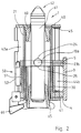
- a holding device 1 is shown in vertical section can be attached to the vehicle frame by means of a mounting plate 3.
- a housing 2 is arranged, the bath wall 4, a top wall 5 and two peripheral walls 6 a, 6 b (see FIG. 6), of which only the leg 7 a of the peripheral wall 6 a in FIG. 1 see is.
- These two peripheral walls 6 a, 6 b extend between the Bottom wall 4 and the top wall 5.
- Bolt 50 in the form of a square tube 51 (see FIG. 6) rotatably arranged has four transom walls 53 a to d.
- the function of the bolt is in In connection with FIG. 6 explained in more detail.
- An actuating handle 52 is arranged on the outside of the transom wall 53 c, with which the bolt can be rotated around its vertical axis.
- the square tube 51 encloses the slide 40, which is shown in the here Embodiment has a cylindrical tube 21.
- an upper cross plate 40 and a lower cross plate at the lower end 41 welded the respective openings for the passage of the pivot 61st or for engaging the clamping element 65, which in the here embodiment shown is a bell nut.
- two slide walls 42a, b arranged between the upper cross plate 40 and the lower cross plate 41 .
- Inside the cylindrical tube 21 is at the top Welded in guide bush 60, in which the pivot 61 is guided.
- two short bolts 23 a, b used, which can be seen more clearly in Figures 3 a and 3 b.
- An inner tube 30 is used, which extends from the lower end to the area Bolts 23 a, b extends and supports them.
- the tensioning element 65 is like this formed that it is in the locking position on the lower end face 33rd of the inner tube 30 abuts.
- the bolts 23 a, b are in the rectangular recess 10 a of the circular opening 9 of the bottom wall 4, whereby the position of the bolts 23 a, b is fixed. Also reach under the bolts 23 a, b with their upper bearing surface 24 the square tube 51st
- the head 62 can be inserted by Pivot 61 in a corresponding opening on the underside of the Locking container this fixed and locked on the chassis become.
- the pivot pin 65 is released after loosening the clamping element rotated and then by screwing in the clamping element 65 tense. So that the tensioning element 65 cannot unintentionally come loose on the lower cross plate 41 and the slide wall 42 a, b a nose trap 66 arranged, which falls automatically into the position shown in Figures 1 and 2 and the cams of the clamping element 65 blocked.
- the tube 21 is shown in two vertical sections.
- Fig. 3 a the installation position of the two bolts 23 a, b is shown, the extend outwards and thus form a first projection 27 a, b.
- the bolts 23 a, b have an upper bearing surface 24 and a lower one Support surface 25 with the square tube 51 of the bolt 50 in the two Interact at high altitudes.
- the bolts 23 a, b extend slightly towards the inside and, as can be seen in particular from FIG. 3 b, on welded to the inner tube 30 extending from the lower end of the tube 21 extends to the bolts 23 a, b.
- the Guide bush 60 At the top of the tube 21 is the Guide bush 60 preferably welded.
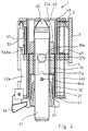
- FIG. 4 shows a further embodiment of the holding device 1 shown. It is a container locking device, in which the pivot 61 can be lowered. 4, the pivot is in shown its lowered position, the slider 20 is in its lower altitude.
- the structure of the holding device 1 differs differ only by different or additional components inside the Tube 21 '.
- the tube 21 ' also has two bolts 23 a, b, which in the same way cooperate with the square tube 51 of the bolt 50, as in Connection with Figures 1 and 2 has already been described. Also at In this embodiment, the bolts 23 a, b of the inner tube 30 ' supported, but which has two recesses 22 a, b, which in Connection with Figures 7 a and b will be described. This Recesses are required so that a link 70 is lowered in the tube 21 ' and can be managed.
- This backdrop 70 which in section and in plan view in Figures 8 a and 8 b is shown, consists of a tube section, the two levels Has side surfaces 72 a and 72 b, in each of which there is a recess 71 a, b is located.
- the pivot pin 61 has two outward-facing driving pins 64 a, b on which when lifting the pivot pin 61 in the recesses 71 a, b of the Intervene backdrop 70.
- the pivot pin 61 is the backdrop 70 also by the driving pins 64 a, b rotated so that the backdrop with the sections that have an outer diameter have, which is slightly smaller than the inner diameter of the tube 21 ', come to rest on the pin 23 a, b.
- the backdrop 70 lies in it on the top of the inward protruding bolts, creating a stable Location of the extended position of the guide bush 60 'and the pivot 61 is reached.
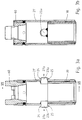
- FIGS. 4 and 5 show the top view of that in FIGS. 4 and 5
- the latch 50 consists of a square tube 51 with the Bolt walls 53 a to d.
- the actuating handle 52 is on the latch wall 53 c arranged, which is arranged parallel to the transom wall 53 c. So that Operating handle 52 is accessible from the outside and is movable, have the only two short peripheral walls 6 a and b of the housing 2 in the left area Legs 7 a, b, so that a rectangular opening 8 remains between them.
- the Slider walls 42 a, b are designed accordingly.
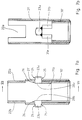
- FIGS. 7 a and b show the tube 21 'of this embodiment.
- the two Bolts 23 a, b form on the inside second projections 28 a, b and point corresponding contact surfaces 26 on which the backdrop 70 in the in the raised position.
Landscapes
- Engineering & Computer Science (AREA)
- Transportation (AREA)
- Mechanical Engineering (AREA)
- Mutual Connection Of Rods And Tubes (AREA)
- Cooling, Air Intake And Gas Exhaust, And Fuel Tank Arrangements In Propulsion Units (AREA)
- Devices For Use In Laboratory Experiments (AREA)
Abstract
Description
Die Erfindung betrifft eine am Fahrgestell eines Fahrzeugs zu befestigende Haltevorrichtung für eine in zwei Höhenlagen arretierbare Container-Verriegelungseinrichtung, die einen Drehzapfen mit einem Spannelement aufweist, wobei die Haltevorrichtung einen in vertikaler Richtung beweglichen Schieber aufweist, der in den beiden Höhenlagen mittels eines Riegels verriegelbar ist.The invention relates to a to be attached to the chassis of a vehicle Holding device for a container locking device that can be locked in two heights, which a pivot with a clamping element has, wherein the holding device movable in the vertical direction Has slide, which in the two altitudes by means of a bolt can be locked.
Aus der DE 31 01 875 C 2 ist beispielhaft eine Container-Verriegelungseinrichtung
bekannt, die auch als Twistlock bezeichnet wird.
Derartige Container-Verriegelungseinrichtungen werden an den Querträgern
oder am Rahmen eines Sattelaufliegers für Container angebracht. Der
Drehzapfen der Container-Verriegelungseinrichtung wird von unten in eine
entsprechende Öffnung im Rahmen des Containers eingeführt, gedreht und
anschließend mittels eines Spannelementes angezogen und somit verriegelt.DE 31 01 875
Man unterscheidet absenkbare und nicht absenkbare Twistlocks, je nachdem ob der Drehzapfen und die Führungsbuchse bei Nichtgebrauch in seinem Gehäuse absenkbar ist oder nicht. Solche absenkbaren Twistlocks werden beispielsweise in DE 21 28 872 beschrieben. Diese Twistlocks haben den Nachteil, daß zusätzliche Handgriffe zum Verriegeln der Führungsbuchse in der oberen Stellung mittels einer Nutenbuchse notwendig sind. A distinction is made between lowerable and non-lowerable twistlocks, depending on whether the pivot and the guide bush in its housing when not in use is lowerable or not. Such lowerable twistlocks are, for example described in DE 21 28 872. These twistlocks have the disadvantage that additional handles for locking the guide bush in the upper one Position using a grooved bushing are necessary.
Da es bei den Sattelaufliegern für Container unterschiedliche Ausführungen gibt, müssen die Container-Verriegelungseinrichtungen an die jeweilige Einbaulage angepasst werden. Bei den sogenannten Gooseneck-Chassis ist der hintere Teil des Rahmens abgesenkt. Auf einem solchen Chassis können sowohl kleinere Container transportiert werden, die auf dem abgesenkten Rahmenteil unmittelbar aufliegen oder auch große Container, die jedoch wegen des Überstandes des Goosenecks auf dem hinteren Rahmenteil nicht aufliegen können. Dies bedeutet, daß die Container-Verriegelungseinrichtung für diese beiden Anwendungsfälle ausgelegt sein muß. Die Container-Verriegelungseinrichtungen, die am hinteren und auch mittleren Rahmenteil solcher Sattelauflieger angeordnet sind, müssen daher in einer oberen und in einer unteren Höhenlage relativ zum Fahrgestell einstellbar sein.Since there are different versions of the semi-trailers for containers there must be the container locking devices to the respective Installation position can be adjusted. The so-called Gooseneck chassis is the lower part of the frame lowered. On such a chassis can Both smaller containers are transported on the lowered one Frame part directly rest or large containers, but because of Do not rest the excess of the gooseneck on the rear frame part can. This means that the container locking device for this both applications must be designed. The container locking devices, those on the rear and middle frame part such semi-trailers are therefore arranged in an upper and in a lower altitude relative to the chassis.
Aus der DE 195 38 915 A 1 ist eine Haltevorrichtung bekannt, mit der die Container-Verriegelungseinrichtung in diesen beiden gewünschten Höhenlagen verriegelbar ist. Solche Haltevorrichtungen weisen einen Schieber auf, der in den beiden Höhenlagen mittels eines in einem Gehäuse gelagerten Riegels, der beispielsweise ein Vierkantrohr sein kann, verriegelbar ist. Die Container-Verriegelungseinrichtung ist unlösbar, vorzugsweise durch Schweißen seitlich an dem Schieber befestigt.From DE 195 38 915 A 1 a holding device is known with which the Container locking device in these two desired altitudes can be locked. Such holding devices have a slide, which in the two altitudes by means of a bolt mounted in a housing, the For example, a square tube can be locked. The container locking device is insoluble, preferably by welding on the side attached to the slider.
Diese bekannte Vorrichtung hat jedoch den Nachteil, daß sie ein großes Gewicht aufweist, einen großen Platzbedarf hat und ein anderes Vormaß besitzt als die Container-Verriegelungseinrichtungen ohne Höhenverstelleinrichtung, weil die Höhenverstelleinrichtung zwischen dem Rahmen und der Container-Verriegelungseinrichtung angeordnet ist. Es müssen daher entsprechende Maßnahmen am Rahmen vorgenommen werden, um den vorgeschriebenen Abstand gegenüberliegender Container-Verriegelungseinrichtungen einhalten zu können. However, this known device has the disadvantage that it is large Has weight, has a large space requirement and has a different measure than the container locking devices without height adjustment device, because the height adjustment device between the frame and the container locking device is arranged. It must therefore be appropriate Measures are taken on the frame to meet the prescribed Keep the distance between opposite container locking devices can.
Aufgabe der Erfindung ist eine Haltevorrichtung für Container-Verriegelungseinrichtungen, die leichter, kompakter und kostengünstiger ist als die bekannten Haltevorrichtungen.The object of the invention is a holding device for container locking devices, which is lighter, more compact and less expensive than the known holding devices.
Diese Aufgabe wird mit einer Haltevorrichtung gelöst, bei der die Container-Verriegelungseinrichtung im Schieber der Haltevorrichtung angeordnet ist.This object is achieved with a holding device in which the container locking device is arranged in the slide of the holding device.
Dadurch, daß die Container-Verriegelungseinrichtung in die Haltevorrichtung integriert ist, entfällt ein zusätzliches Gehäuse sowie die üblicherweise vorhandene Nutenbuchse. Durch den Wegfall dieser Bauteile wird Gewicht eingespart. Außerdem wird durch die Integration der Container-Verriegelungseinrichtung in die Haltevorrichtung der Drehzapfen näher am Fahrzeugrahmen angeordnet, so daß ohne zusätzliche Maßnahmen übliches Vormaß von Twistlocks eingehalten werden kann.The fact that the container locking device in the holding device is integrated, there is no additional housing or the usual existing grooved bush. By eliminating these components, weight becomes saved. In addition, the integration of the container locking device in the holder of the pivot closer to Vehicle frame arranged so that usual without additional measures Pre-measure of twistlocks can be maintained.
Vorzugsweise weist der Schieber ein Rohr auf, in dem der Drehzapfen verschiebbar gelagert ist. Der Drehzapfen kann daher mittig in der Haltevorrichtung angeordnet werden.Preferably, the slide has a tube in which the pivot pin is slidably mounted. The pivot can therefore be centered in the Holding device can be arranged.
Das Rohr weist vorzugsweise an seiner Außenseite mindestens einen ersten Vorsprung auf, der in den beiden Höhenlagen mit dem Riegel zusammenwirkt. In der unteren Höhenlage untergreift dieser Vorsprung den Riegel, während in der oberen Höhenlage der Vorsprung auf dem Riegel aufliegt. Es können dadurch zwei stabile Positionen eingestellt werden.The tube preferably has at least one first on its outside Projection that interacts with the bolt at both altitudes. In the lower altitude, this projection engages under the bolt, while in the upper height of the projection rests on the bolt. It can thereby setting two stable positions.
Gleichzeitig dienen die Vorsprünge zur Verdrehsicherheit des Systems.At the same time, the projections serve to prevent the system from rotating.
Vorzugsweise ist das Rohr senkrecht zu seiner Längsachse von mindestens einem Bolzen durchsetzt, dessen eines Ende den ersten Vorsprung bildet und dessen anderes Ende gegenüber der Rohrwand nach innen vorsteht. Der Bolzen erstreckt sich nicht wie bei den Vorrichtungen gemäß dem Stand der Technik durch das Innere des Rohrs, sondern ist verkürzt ausgebildet, damit im Innern des Rohrs der Drehzapfen und gegebenenfalls weitere Bauteile eingesetzt und bewegt werden können, die für die Verschiebung des Drehzapfens erforderlich sind.The tube is preferably perpendicular to its longitudinal axis of at least penetrated by a bolt, one end of which forms the first projection and the other end of which protrudes inward from the pipe wall. The bolt does not extend as in the prior art devices through the inside of the tube, but is shortened, so inside the tube of the pivot and, if necessary, other components are used and can be moved, which is required for the displacement of the pivot are.
Vorzugsweise werden an gegenüberliegenden Seiten des Rohrs zwei Bolzen vorgesehen, die bei dieser Ausführungsform zwei erste Vorsprünge bilden.Preferably two bolts are on opposite sides of the tube provided that form two first projections in this embodiment.
Da der oder die Bolzen eine kurze Baulänge aufweisen und nur mittig in der Rohrwand gehalten werden, andererseits aber große Kräfte aufnehmen müssen, ist es für die Stabilität des Bolzens vorteilhaft, wenn das Rohr zusätzlich ein Innenrohr aufweist, das sich vom unteren Ende des Rohrs bis zum Bolzen erstreckt und diesen abstützt. Da in der Verriegelungsposition Kräfte auf den Bolzen einwirken und andererseits das Spannelement Kräfte von unten einleitet, ist es von Vorteil, wenn sich das Spannelement an der unteren Stirnfläche da Innenrohrs und nicht an der Stirnfläche des Rohrs abstützt. Das Spannelement und das Innenrohr sind daher entsprechend ausgebildet.Because the bolt or bolts have a short length and only in the middle of the Pipe wall are held, but on the other hand have to absorb large forces, it is advantageous for the stability of the bolt if the tube is an additional one Has inner tube that extends from the lower end of the tube to the bolt extends and supports this. Since in the locking position forces on the Act bolts and on the other hand the clamping element forces from below initiates, it is advantageous if the clamping element on the lower The end face is supported by the inner tube and not by the end face of the tube. The The clamping element and the inner tube are therefore designed accordingly.
Vorzugsweise ist das Innenrohr mit dem oder den Bolzen verschweißt.The inner tube is preferably welded to the bolt or bolts.
Wenn es sich um eine Container-Verriegelungseinrichtung handelt, bei der der Drehzapfen nicht absenkbar ist, ist eine Führungsbuchse für den Drehzapfen am oberen Ende des Rohrs befestigt. Die Führungsbuchse kann beispielsweise in das Rohr eingeschweißt sein.If it is a container locking device in which the Pivot is not a guide bushing for the pivot attached to the top of the tube. The guide bush can, for example be welded into the pipe.
Wenn der Drehzapfen absenkbar ausgebildet sein soll, ist anstelle der sonst üblicherweise vorhandenen Nutenbuchse vorteilhafterweise oberhalb des Innenrohrs eine in einer angehobenen und einer abgesenkten Position verschiebbare Kulisse vorgesehen. Der Bolzen, der gegenüber dem Rohr nach außen vorsteht und einen ersten Vorsprung bildet, übernimmt in dieser Ausführungsform eine zusätzliche Abstützfunktion, die dadurch zustande kommt, daß der Bolzen im Innern des Rohrs einen zweiten Vorsprung bildet, auf dem sich die Kulisse in der angehobenen Position abstützt.If the pivot is to be designed to be lowerable, instead of that Usually existing grooved bush advantageously above Inner tube one in a raised and a lowered position slidable backdrop provided. The bolt that is opposite the pipe protrudes outside and forms a first lead, takes over in this Embodiment an additional support function, which is thereby comes that the bolt forms a second projection inside the tube, on which the backdrop is supported in the raised position.
Die Kulisse besteht vorzugsweise aus einem Rohrstück, dessen Außendurchmesser geringfügig kleiner ist als der Innendurchmesser des Rohrs, so daß die Kulisse im Rohr geführt wird. Dadurch, daß die Kulisse während des Verschiebens von der abgesenkten in die angehobene Position und umgekehrt an dem oder den Bolzen vorbeibewegt werden muß, muß der Außendurchmesser an der betreffenden Stelle entsprechend verringert sein. Die Kulisse weist daher mindestens eine gegenüber dem Außenumfang zurückversetzte ebene Seitenfläche zum Vorbeiführen am Bolzen auf. Die Anzahl der ebenen Seitenflächen entspricht der Anzahl der im Rohr vorhandenen zweiten Vorsprünge.The backdrop preferably consists of a piece of pipe, the Outside diameter is slightly smaller than the inside diameter of the pipe, so that the backdrop is guided in the pipe. Because the backdrop during moving from the lowered to the raised position and vice versa must be moved past the bolt or bolts, the Outside diameter at the point in question must be reduced accordingly. The The backdrop therefore has at least one in relation to the outer circumference recessed flat side surface for passing the bolt on. The The number of flat side faces corresponds to the number in the tube existing second tabs.
Der Drehzapfen durchgreift vorzugsweise die Kulisse und weist unterhalb der Kulisse mindestens einen nach außen vorstehenden Mitnahmestift auf, der beim Anheben des Drehzapfens in eine im Bereich der ebenen Seitenfläche befindliche Ausnehmung eingreift. Mittels des Mitnahmestiftes ist es möglich, die Kulisse mittels des Drehzapfens zu ergreifen, anzuheben und zu drehen, so daß sie nach dem Vorbeiführen an dem zweiten Vorsprung in der angehobenen Position auf dem zweiten Vorsprung aufliegt.The pivot pin preferably extends through the backdrop and points below Set at least one protruding pin that protrudes from the outside Lift the pivot into one in the area of the flat side surface located recess engages. With the drive pin it is possible to to grasp, raise and turn the backdrop by means of the pivot, so that after passing the second projection in the raised Position on the second projection.
Auf der Kulisse liegt die Führungsbuchse. Die sonst übliche Nutenbuchse entfällt.The guide bush lies on the backdrop. The usual grooved bush not applicable.
Die Haltevorrichtung weist vorzugsweise mindestens einen Führungsstab mit einer Federeinrichtung auf, mit dem der Schieber geführt wird. Die Federeinrichtung dient dazu, den Hubvorgang der Haltevorrichtung zu unterstützen. Der Führungsstab ist vorzugsweise zwischen einer Befestigungsplatte für die Montage am Fahrgestell des Fahrzeugs und dem Schieber angeordnet, wodurch eine insgesamt kompakte Ausführung erreicht wird.The holding device preferably has at least one guide rod a spring device with which the slide is guided. The Spring device serves to close the lifting process of the holding device support. The guide rod is preferably between one Mounting plate for mounting on the chassis of the vehicle and the Slider arranged, which achieves an overall compact design becomes.
Der Riegel, der vorzugsweise aus einem den Schieber umgreifenden Vierkantrohr besteht, besitzt einen Betätigungsgriff, der sich parallel zu einer der Riegelwände erstreckt. In der Verriegelungsposition liegt der Griff parallel zum Fahrzeug, so daß der Betätigungsgriff einerseits nicht nach außen vorsteht und zum anderen sofort erkennbar ist, ob sich der Riegel in Verriegelungsposition befindet.The bolt, which preferably consists of a gripping around the slide Square tube exists, has an operating handle that is parallel to one the bolt walls extends. In the locked position, the handle is parallel to the vehicle so that the operating handle does not protrude on the one hand and on the other hand it is immediately recognizable whether the bolt is in Locked position.
Vorzugsweise ist der Griff auf der der Befestigungsplatte abgewandten Seite des Riegels befestigt. Beispielhafte Ausführungsformen der Erfindung werden nachfolgend anhand der Zeichnung näher erläutert.The handle is preferably on the side facing away from the fastening plate of the bolt attached. Exemplary embodiments of the invention explained below with reference to the drawing.
Es zeigen:
- Fig. 1
- einen Vertikalschnitt durch eine Haltevorrichtung mit nicht absenkbarem Twistlock in der unteren Höhenlage,
- Fig. 2
- die in Fig. 1 gezeigte Vorrichtung in der oberen Höhenlage,
- Fig. 3a u. b
- Vertikalschnitte durch Rohr, Innenrohr und Führungsbuchse des nicht absenkbaren Twistlock,
- Fig. 4
- einen Vertikalschnitt durch eine Haltevorrichtung mit einem absenkbaren Twistlock in der unteren Höhenlage in abgesenkter Position,
- Fig. 5
- die in Fig. 4 gezeigte Haltevorrichtung in der oberen Höhenlage mit ausgefahrenem Twistlock,
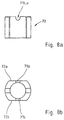
- Fig. 6
- eine Draufsicht auf die in
den Figuren 4 und 5 gezeigte Haltevorrichtung, - Fig. 7a u. b
- zwei Vertikalschnitte durch das Rohr und das Innenrohr für den absenkbaren Twistlock und
- Fig. 8a u. b
- einen Vertikalschnitt durch die Kulisse sowie eine Draufsicht auf die Kulisse.
- Fig. 1
- a vertical section through a holding device with a non-lowerable twist lock in the lower altitude,
- Fig. 2
- 1 in the upper elevation,
- Fig. 3a u. b
- Vertical cuts through the tube, inner tube and guide bush of the non-lowerable twistlock,
- Fig. 4
- a vertical section through a holding device with a lowerable twist lock in the lower height in the lowered position,
- Fig. 5
- 4 in the upper altitude with the twist lock extended,
- Fig. 6
- 3 shows a plan view of the holding device shown in FIGS. 4 and 5,
- Fig. 7a u. b
- two vertical sections through the tube and the inner tube for the lowerable twistlock and
- Fig. 8a u. b
- a vertical section through the backdrop and a top view of the backdrop.
In der Fig. 1 ist eine Haltevorrichtung 1 im Vertikalschnitt dargestellt, die
mittels einer Befestigungsplatte 3 am Fahrzeugrahmen befestigt werden kann.
An der Befestigungsplatte 3 ist ein Gehäuse 2 angeordnet, das eine Badenwand
4, eine Deckwand 5 sowie zwei Umfangswände 6 a, 6 b (s. Fig. 6) aufweist,
von denen in der Fig. 1 lediglich der Schenkel 7 a der Umfangswand 6 a zu
sehen ist. Diese beiden Umfangswände 6 a, 6 b erstrecken sich zwischen der
Bodenwand 4 und der Deckwand 5.In Fig. 1, a holding
Im Innern des Gehäuses 2 ist zwischen Bodenwand 4 und Deckwand 5 ein
Riegel 50 in Form eines Vierkantrohres 51 (s. Fig. 6) drehbar angeordnet, der
vier Riegelwände 53 a bis d aufweist. Die Funktion des Riegels wird im
Zusammenhang mit der Fig. 6 noch näher erläutert.Inside the
An der Außenseite der Riegelwand 53 c ist ein Betätigungsgriff 52 angeordnet,
mit dem der Riegel um seine vertikale Achse gedreht werden kann.An actuating handle 52 is arranged on the outside of the
Das Vierkantrohr 51 umschließt den Schieber 40, der in der hier gezeigten
Ausführungform ein zylindrisches Rohr 21 aufweist. Am oberen Ende des
Rohrs ist eine obere Querplatte 40 und am unteren Ende eine untere Querplatte
41 angeschweißt, die jeweils Öffnungen für den Durchtritt des Drehzapfens 61
bzw. zum Eingreifen des Spannelementes 65 aufweisen, das in der hier
gezeigten Ausführungsform eine Glockenmutter ist. Ferner sind zwischen der
oberen Querplatte 40 und der unteren Querplatte 41 zwei Schieberwände 42a,b
angeordnet. Im Innern des zylindrischen Rohrs 21 ist am oberen Ende eine
Führungsbuchse 60 eingeschweißt, in der der Drehzapfen 61 geführt ist. Etwa
in der Mitte des zylindrischen Rohrs 21 sind zwei kurze Bolzen 23 a, b
eingesetzt, die deutlicher in den Figuren 3 a und 3 b zu sehen sind. Im unteren
Bereich ist ein Innenrohr 30 eingesetzt, das sich vom unteren Ende bis zu den
Bolzen 23 a, b erstreckt und diese abstützt. Das Spannelement 65 ist so
ausgebildet, daß es in der Verriegelungsposition an der unteren Stirnfläche 33
des Innenrohrs 30 anliegt.The
In der unteren Höhenlage befinden sich die Bolzen 23 a, b in der
rechtwinkligen Ausnehmung 10 a der kreisförmigen Öffnung 9 der Bodenwand
4, wodurch die Lage der Bolzen 23 a, b fixiert wird. Außerdem untergreifen
die Bolzen 23 a, b mit ihrer oberen Auflagefläche 24 das Vierkantrohr 51.In the lower altitude, the
In der Fig. 2 ist die angehobene Position der Container-Verriegelungseinrichtung
dargestellt. Durch Drehen des Vierkantrohrs 51, was
mittels des Betätigungsgriffes 52 erfolgt, wird der Weg für die Bolzen 23 a, b
freigemacht, so daß das Rohr 21 nach oben geschoben werden kann, bis sich
die Bolzen 23 a, b oberhalb des Riegels 50 befinden. Der Riegel 50 wird darin
in seine Verriegelungsposition zurückgedreht, wodurch die Bolzen 23 a, b und
mit ihrer Auflagefläche 25 auf der oberen Stirnfläche des Vierkantrohrs 21
aufliegen. Während des Hochschiebens wird der Schieber in den beiden
Führungsstäben 44 a, b, wovon lediglich 44 b in den Figuren 1 und 2 zu sehen
ist, geführt. Mindestens ein Führungsstab 44 a, b weist eine Federeinrichtung
45 auf, die den Hubvorgang unterstützt. Die Feder ist deshalb zwischen der
oberen Querplatte 40 und der Bodenwand 4 angeordnet. In der Deckwand 5 ist
eine entsprechend große Öffnung vorgesehen, durch die sich sowohl der
Führungsstab 44 a, b als auch die Federeinrichtung 45 erstreckt. 2 is the raised position of the container locking device
shown. By turning the
In den beiden gezeigten Höhenlagen kann durch Einführen des Kopfes 62 des
Drehzapfens 61 in eine entsprechende Öffnung an der Unterseite des zu
verriegelnden Containers dieser auf dem Fahrgestell fixiert und verriegelt
werden. Hierzu wird der Drehzapfen nach dem Lösen des Spannelementes 65
gedreht und anschließend durch Einschrauben des Spannelementes 65
verspannt. Damit sich das Spannelement 65 nicht unbeabsichtigt lösen kann, ist
an der unteren Querplatte 41 und der Schieberwand 42 a, b eine Nasenfalle 66
angeordnet, die von selbst in die in den Figuren 1 und 2 gezeigte Position fällt
und die Nocken des Spannelementes 65 blockiert.In the two altitudes shown, the
In den Figuren 3 a und b ist das Rohr 21 in zwei Vertikalschnitten dargestellt.
In der Fig. 3 a ist die Einbaulage der beiden Bolzen 23 a, b dargestellt, die
sich nach außen erstrecken und somit einen ersten Vorsprung 27 a, b bilden.
Die Bolzen 23 a, b besitzen eine obere Auflagefläche 24 und eine untere
Auflagefläche 25, die mit dem Vierkantrohr 51 des Riegels 50 in den beiden
Höhenlagen zusammenwirken. Die Bolzen 23 a, b erstrecken sich geringfügig
nach innen und sind, wie insbesondere aus der Fig. 3 b zu entnehmen ist, an
dem Innenrohr 30 angeschweißt, das sich von dem unteren Ende des Rohrs 21
bis zu den Bolzen 23 a, b erstreckt. Am oberen Ende des Rohres 21 ist die
Führungsbuchse 60 vorzugsweise eingeschweißt.In Figures 3a and b, the
In der Fig. 4 ist eine weitere Ausführungsform der Haltevorrichtung 1
dargestellt. Es handelt sich hier um eine Container-Verriegelungseinrichtung,
bei der der Drehzapfen 61 absenkbar ist. In der Fig. 4 ist der Drehzapfen in
seiner abgesenkten Position dargestellt, wobei der Schieber 20 sich in seiner
unteren Höhenlage befindet. Der Aufbau der Haltevorrichtung 1 unterscheidet
sich lediglich durch unterschiedliche bzw. zusätzliche Bauteile im Innern des
Rohrs 21'. Das Rohr 21' unterscheidet sich von dem in den Figuren 1 und 2
beschriebenen Rohr 21 dadurch, daß im oberen Bereich rechteckige
Ausnehmungen 22a, b vorgesehen sind, in die die in der Fig. 5 gezeigten
Pratzen 63a, b des Kopfes 62 des Drehzapfens 61 in der abgesenkten Position,
und die Führungselemente 73a, b der Führungsbuchse 60 bzw. der
Führungsbuchse 60' in der oberen Position eingreifen können.4 shows a further embodiment of the holding
Das Rohr 21' weist ebenfalls zwei Bolzen 23 a, b auf, die in gleicher Weise
mit dem Vierkantrohr 51 des Riegels 50 zusammenwirken, wie dies im
Zusammenhang mit den Figuren 1 und 2 bereits beschrieben wurde. Auch bei
dieser Ausführungsform werden die Bolzen 23 a, b von dem Innenrohr 30'
abgestützt, das allerdings zwei Ausnehmungen 22 a, b aufweist, was im
Zusammenhang mit den Figuren 7 a und b noch beschrieben wird. Diese
Ausnehmungen sind erforderlich, damit eine Kulisse 70 im Rohr 21' abgesenkt
und geführt werden kann.The tube 21 'also has two
Diese Kulisse 70, die im Schnitt und in der Draufsicht in den Figuren 8 a und
8 b dargestellt ist, besteht aus einem Rohrabschnitt, der zwei ebene
Seitenflächen 72 a und 72 b aufweist, in denen sich jeweils eine Ausnehmung
71 a, b befindet.This
Der Drehzapfen 61 weist zwei nach außen weisende Mitnahmestifte 64 a, b
auf, die beim Anheben des Drehzapfens 61 in die Ausnehmungen 71 a, b der
Kulisse 70 eingreifen. Wenn der Drehzapfen 61 zum Erreichen der
ausgefahren Position angehoben wird, wird gleichzeitig die Kulisse 70 und
die daraufliegende Führungsbuchse 60' angehoben, wobei die beiden ebenen
Seitenflächen 72 a, b an den Bolzen 23 a, b vorbeigeführt werden, bis sich die
Kulisse 70 oberhalb der Bolzen 23 a, b befindet. Durch Drehen des
Drehzapfens 61 wird die Kulisse 70 ebenfalls durch die Mitnahmestifte 64 a, b
gedreht, so daß die Kulisse mit den Abschnitten, die einen Außendurchmesser
aufweisen, der geringfügig kleiner ist, als der Innendurchmesser des Rohrs
21', über den Zapfen 23 a, b zu liegen kommen. Die Kulisse 70 legt sich darin
auf die Oberseite der nach innen vorstehenden Bolzen, wodurch eine stabile
Lage der ausgefahrenen Position der Führungsbuchse 60' und des Drehzapfens
61 erreicht wird. The
In der Fig. 5 ist diese ausgefahrene Position des Drehzapfens 60 und
gleichzeitig die obere Höhenlage der Haltevorrichtung 1 dargestellt. Da hierbei
der Drehzapfen 61 gedreht worden ist, werden die Pratzen 63 a, b des Kopfes
62 sichtbar. Die Verriegelung und das Verschieben zum Erreichen der oberen
Höhenlage erfolgt in der gleichen Weise wie im Zusammenhang mit den
Figuren 1 und 2 beschrieben wurde.5, this extended position of the
In der Fig. 6 ist die Draufsicht auf die in den Figuren 4 und 5 dargestellt
Vorrichtung zu sehen, wobei die Ausgestaltung des Gehäuses 2 und des
Riegels 50 auch für die Ausführungsform zutrifft, die in den Figuren 1 und 2
dargestellt ist. Der Riegel 50 besteht aus einem Vierkantrohr 51 mit den
Riegelwänden 53 a bis d. An der Riegelwand 53 c ist der Betätigungsgriff 52
angeordnet, der parallel zur Riegelwand 53 c angeordnet ist. Damit der
Betätigungsgriff 52 von außen zugänglich ist und bewegbar ist, besitzen die
beiden Umfangswände 6 a und b des Gehäuses 2 im linken Bereich nur kurze
Schenkel 7 a, b, so daß dazwischen eine rechteckige Öffnung 8 verbleibt. Die
Schieberwände 42 a, b sind entsprechend ausgebildet.6 shows the top view of that in FIGS. 4 and 5
To see device, the design of the
Wem der Griff 52 in die gestrichelte Position bewegt wird, wird der Riegel
entriegelt, was bedeutet, daß sich die Bolzen 23 a, b im Bereich der diagonal
gegenüberliegenden Eckpunkte des Vierkantrohrs 51 befinden, wodurch das
Rohr 21' mit den Bolzen 23 a, b in vertikale Richtung verschiebbar wird.
Nach Erreichen der jeweiligen Höhenlage, wird der Griff 52 und damit das
Vierkantrohr 51 wieder in die Ausgangslage, also in die Verriegelungslage,
zurückgedreht, so daß die Bolzen 23 a, b entweder mit ihrer Oberseite oder
mit ihrer Unterseite an dem Vierkantrohr 51 aufliegen.Whoever moves the
In den Figuren 7 a und b ist das Rohr 21' dieser Ausführungsform dargestellt.
Es sind im oberen Bereich die beiden rechteckigen Ausnehmungen 22 a, b
dargestellt, in die Führungselemente der Führungsbuchse 60' und die Pratzen
63a,b in der abgesenkten Position des Drehzapfens 61 eingreifen. Die beiden
Bolzen 23 a, b bilden an der Innenseite zweite Vorsprünge 28 a, b und weisen
entsprechende Auflageflächen 26 auf, auf denen die Kulisse 70 in der
angehobenen Position aufliegt.FIGS. 7 a and b show the tube 21 'of this embodiment.
There are the two
Die Bolzen 23 a, b sind ebenfalls an einem Innenrohr 30' angeschweißt, wobei jedoch im Gegensatz zu der ersten Ausführungsform Ausnehmungen 31a, b vorgesehen sind, um die Kulisse 70 in ihrer abgesenkten Position aufnehmen zu können. Bezugszeichen
- 1
- Haltevorrichtung
- 2
- Gehäuse
- 3
- Befestigungsplatte
- 4
- Bodenwand
- 5
- Deckwand
- 6 a, b
- Umfangswand
- 7 a, b
- Schenkel
- 8
- rechteckige Öffnung
- 9
- kreisförmige Öffnung
- 10 a, b
- rechteckige Aussparung
- 20
- Schieber
- 21, 21'
- Rohr
- 22 a, b
- rechteckige Ausnehmung
- 23 a, b
- Bolzen
- 24
- obere Auflagefläche
- 25
- untere Auflagefläche
- 26
- innere Auflagefläche
- 27 a, b
- erster Vorsprung
- 28 a, b
- zweiter Vorsprung
- 30, 30'
- Innenrohr
- 31 a, b
- Ausnehmung
- 33
- untere Stirnfläche
- 40
- obere Querplatte
- 41
- untere Querplatte
- 42 a, b
- Schieberwand
- 43
- Öffnung
- 44 a, b
- Führungsstab
- 45
- Feder
- 50
- Riegel
- 51
- Vierkantrohr
- 52
- Betätigungsgriff
- 53 a,b,c,d
- Riegelwand
- 60, 60'
- Führungsbuchse
- 61
- Drehzapfen
- 62
- Kopf
- 63 a, b
- Pratze
- 64 a, b
- Mitnahmestift
- 65
- Spannelement
- 66
- Nasenfalle
- 70
- Kulisse
- 71 a, b
- Ausnehmung
- 72 a, b
- ebene Seitenfläche
- 73 a, b
- Führungselement der Führungsbuchse
- 1
- Holding device
- 2nd
- casing
- 3rd
- Mounting plate
- 4th
- Bottom wall
- 5
- Top wall
- 6 a, b
- Peripheral wall
- 7 a, b
- leg
- 8th
- rectangular opening
- 9
- circular opening
- 10 a, b
- rectangular recess
- 20th
- Slider
- 21, 21 '
- pipe
- 22 a, b
- rectangular recess
- 23 a, b
- bolt
- 24th
- upper contact surface
- 25th
- lower contact surface
- 26
- inner contact surface
- 27 a, b
- first lead
- 28 a, b
- second lead
- 30, 30 '
- Inner tube
- 31 a, b
- Recess
- 33
- lower face
- 40
- upper cross plate
- 41
- lower cross plate
- 42 a, b
- Slider wall
- 43
- opening
- 44 a, b
- Executive staff
- 45
- feather
- 50
- bars
- 51
- Square tube
- 52
- Operating handle
- 53 a, b, c, d
- Bolt wall
- 60, 60 '
- Guide bushing
- 61
- Pivot
- 62
- head
- 63 a, b
- Claw
- 64 a, b
- Driving pin
- 65
- Clamping element
- 66
- Nasal trap
- 70
- Backdrop
- 71 a, b
- Recess
- 72 a, b
- flat side surface
- 73 a, b
- Guide element of the guide bush
Claims (16)
Applications Claiming Priority (2)
| Application Number | Priority Date | Filing Date | Title |
|---|---|---|---|
| DE1997155638 DE19755638C2 (en) | 1997-12-15 | 1997-12-15 | Holding device for a container locking device that can be locked at two heights |
| DE19755638 | 1997-12-15 |
Publications (1)
| Publication Number | Publication Date |
|---|---|
| EP0926002A1 true EP0926002A1 (en) | 1999-06-30 |
Family
ID=7851937
Family Applications (1)
| Application Number | Title | Priority Date | Filing Date |
|---|---|---|---|
| EP98122963A Withdrawn EP0926002A1 (en) | 1997-12-15 | 1998-12-03 | Support for a container locking device which can be positioned at two different heights |
Country Status (4)
| Country | Link |
|---|---|
| EP (1) | EP0926002A1 (en) |
| BG (1) | BG63004B1 (en) |
| DE (1) | DE19755638C2 (en) |
| PL (1) | PL187775B1 (en) |
Families Citing this family (4)
| Publication number | Priority date | Publication date | Assignee | Title |
|---|---|---|---|---|
| DE10148728C1 (en) * | 2001-10-02 | 2003-05-15 | Schmitz Gotha Fahrzeugwerke | Locking arrangement for containers |
| DE10202190B4 (en) * | 2002-01-22 | 2006-10-19 | Jost-Werke Gmbh & Co. Kg | Container locking device |
| DE102006043777B4 (en) * | 2006-09-14 | 2009-09-10 | Jost-Werke Gmbh | Device for adjusting the vertical position of a container lock |
| EP2708416B1 (en) * | 2012-09-18 | 2019-02-13 | Agueda Losada Alvarez | Adjustable system to attach containers to transport vehicles |
Citations (6)
| Publication number | Priority date | Publication date | Assignee | Title |
|---|---|---|---|---|
| GB1265793A (en) * | 1968-03-19 | 1972-03-08 | ||
| DE2128872A1 (en) | 1971-03-23 | 1972-12-21 | Schulz, Gerd, 2000 Hamburg | Twist lock |
| DE3101875A1 (en) | 1981-01-22 | 1982-08-05 | Jost-Werke GmbH, 6078 Neu Isenburg | Container mounting device |
| WO1996002446A1 (en) * | 1994-07-18 | 1996-02-01 | Loevgren Sten | A device in holding elements |
| DE29622249U1 (en) * | 1995-12-13 | 1997-02-20 | Piñeiro Bouza, Manuel, Zaragoza | Anchoring for containers with multiple positioning |
| DE19538915A1 (en) | 1995-10-19 | 1997-04-24 | Jost Werke Ag | Holding device for container locking device |
Family Cites Families (2)
| Publication number | Priority date | Publication date | Assignee | Title |
|---|---|---|---|---|
| EP0301876B1 (en) * | 1987-07-30 | 1992-03-25 | Multi-Stroke Handbrake Controls Limited | Twistlocks |
| DE19638471C1 (en) * | 1996-09-20 | 1997-12-11 | Schneider Fahrzeug Und Contain | Locking devices for containers on motor vehicles |
-
1997
- 1997-12-15 DE DE1997155638 patent/DE19755638C2/en not_active Expired - Fee Related
-
1998
- 1998-11-20 BG BG102941A patent/BG63004B1/en unknown
- 1998-12-03 EP EP98122963A patent/EP0926002A1/en not_active Withdrawn
- 1998-12-14 PL PL33027098A patent/PL187775B1/en unknown
Patent Citations (6)
| Publication number | Priority date | Publication date | Assignee | Title |
|---|---|---|---|---|
| GB1265793A (en) * | 1968-03-19 | 1972-03-08 | ||
| DE2128872A1 (en) | 1971-03-23 | 1972-12-21 | Schulz, Gerd, 2000 Hamburg | Twist lock |
| DE3101875A1 (en) | 1981-01-22 | 1982-08-05 | Jost-Werke GmbH, 6078 Neu Isenburg | Container mounting device |
| WO1996002446A1 (en) * | 1994-07-18 | 1996-02-01 | Loevgren Sten | A device in holding elements |
| DE19538915A1 (en) | 1995-10-19 | 1997-04-24 | Jost Werke Ag | Holding device for container locking device |
| DE29622249U1 (en) * | 1995-12-13 | 1997-02-20 | Piñeiro Bouza, Manuel, Zaragoza | Anchoring for containers with multiple positioning |
Also Published As
| Publication number | Publication date |
|---|---|
| DE19755638A1 (en) | 1999-06-24 |
| PL187775B1 (en) | 2004-10-29 |
| DE19755638C2 (en) | 1999-10-07 |
| BG63004B1 (en) | 2001-01-31 |
| PL330270A1 (en) | 1999-06-21 |
| BG102941A (en) | 1999-06-30 |
Similar Documents
| Publication | Publication Date | Title |
|---|---|---|
| DE19538988A1 (en) | Table bridging device | |
| DE69809031T2 (en) | VEHICLE LOADING DEVICE | |
| EP0051107B1 (en) | Device in particular for the frontal locking of containers | |
| DE19755638C2 (en) | Holding device for a container locking device that can be locked at two heights | |
| DE2648281B2 (en) | Support device for a ceiling formwork element | |
| EP0681890A1 (en) | Work or assembly trestle | |
| EP0401404B1 (en) | Vertically adjustable mounting for a trailer hitch | |
| DE2736222A1 (en) | Body fixing for heavy vehicle chassis - has fluid cylinder operated latch hooking into chassis aperture to allow change of use | |
| EP3222464B1 (en) | Frame system for motor vehicle structures | |
| DE2260436A1 (en) | DEVICE FOR LOCKING CONTAINERS ON VEHICLES | |
| DE19538915B4 (en) | On the chassis of a vehicle to be fastened holding device for a container locking device | |
| DE69308902T2 (en) | Tillage machine | |
| DE3025976A1 (en) | DEVICE FOR LOCKING CONNTAINERS ON VEHICLES | |
| DE4339670C2 (en) | Locking system for changing devices for use in trucks and element for use in such a system | |
| EP1300285A1 (en) | Arrangement for locking of different types of containers on a chassis | |
| DE4336185C2 (en) | Golf cart | |
| DE69201370T2 (en) | Container for transporting ejection seats. | |
| DE29603128U1 (en) | Jig | |
| DE29803330U1 (en) | Lifting device | |
| DE1953813A1 (en) | Locking device for container | |
| DE9216461U1 (en) | Underrun protection for trucks | |
| DE19826106A1 (en) | Device to connect stay tube of esp. lifting platform to vehicle | |
| DE9421370U1 (en) | Rollover protection device for a motor vehicle | |
| EP0247283A2 (en) | Brace for tying down detachable car bodies, particularly for vehicles | |
| DE1917824A1 (en) | Device for holding a load |
Legal Events
| Date | Code | Title | Description |
|---|---|---|---|
| PUAI | Public reference made under article 153(3) epc to a published international application that has entered the european phase |
Free format text: ORIGINAL CODE: 0009012 |
|
| AK | Designated contracting states |
Kind code of ref document: A1 Designated state(s): DE ES FR GB IT NL |
|
| AX | Request for extension of the european patent |
Free format text: AL;LT;LV;MK;RO;SI |
|
| 17P | Request for examination filed |
Effective date: 19990624 |
|
| AKX | Designation fees paid |
Free format text: DE ES FR GB IT NL |
|
| RAP1 | Party data changed (applicant data changed or rights of an application transferred) |
Owner name: JOST-WERKE GMBH & CO. KG |
|
| STAA | Information on the status of an ep patent application or granted ep patent |
Free format text: STATUS: THE APPLICATION IS DEEMED TO BE WITHDRAWN |
|
| 18D | Application deemed to be withdrawn |
Effective date: 20020702 |