EP0925423B1 - Vorrichtung und verfahren zum perforieren und stimulieren einer gesteinsformation - Google Patents
Vorrichtung und verfahren zum perforieren und stimulieren einer gesteinsformation Download PDFInfo
- Publication number
- EP0925423B1 EP0925423B1 EP97935002A EP97935002A EP0925423B1 EP 0925423 B1 EP0925423 B1 EP 0925423B1 EP 97935002 A EP97935002 A EP 97935002A EP 97935002 A EP97935002 A EP 97935002A EP 0925423 B1 EP0925423 B1 EP 0925423B1
- Authority
- EP
- European Patent Office
- Prior art keywords
- perforating
- propellant
- charge
- sleeve
- subterranean formation
- Prior art date
- Legal status (The legal status is an assumption and is not a legal conclusion. Google has not performed a legal analysis and makes no representation as to the accuracy of the status listed.)
- Expired - Lifetime
Links
- 230000015572 biosynthetic process Effects 0.000 title claims description 57
- 238000000034 method Methods 0.000 title claims description 19
- 230000004936 stimulating effect Effects 0.000 title claims description 13
- 239000003380 propellant Substances 0.000 claims description 55
- 239000012530 fluid Substances 0.000 claims description 22
- 239000002360 explosive Substances 0.000 claims description 15
- 239000000463 material Substances 0.000 claims description 11
- 238000005474 detonation Methods 0.000 claims description 10
- 239000004593 Epoxy Substances 0.000 claims description 6
- XLYOFNOQVPJJNP-UHFFFAOYSA-N water Substances O XLYOFNOQVPJJNP-UHFFFAOYSA-N 0.000 claims description 6
- 238000004891 communication Methods 0.000 claims description 5
- 239000007800 oxidant agent Substances 0.000 claims description 5
- 230000002706 hydrostatic effect Effects 0.000 claims description 3
- 230000000149 penetrating effect Effects 0.000 claims description 2
- 238000005755 formation reaction Methods 0.000 description 49
- 239000007789 gas Substances 0.000 description 22
- 239000002800 charge carrier Substances 0.000 description 16
- 244000309464 bull Species 0.000 description 14
- 238000012546 transfer Methods 0.000 description 10
- 239000004576 sand Substances 0.000 description 6
- 238000010304 firing Methods 0.000 description 5
- 238000004519 manufacturing process Methods 0.000 description 5
- 241000237509 Patinopecten sp. Species 0.000 description 3
- 238000009527 percussion Methods 0.000 description 3
- 235000020637 scallop Nutrition 0.000 description 3
- 229920000049 Carbon (fiber) Polymers 0.000 description 2
- 239000004917 carbon fiber Substances 0.000 description 2
- 239000004568 cement Substances 0.000 description 2
- 239000002131 composite material Substances 0.000 description 2
- 230000007423 decrease Effects 0.000 description 2
- 238000013461 design Methods 0.000 description 2
- 230000001976 improved effect Effects 0.000 description 2
- VNWKTOKETHGBQD-UHFFFAOYSA-N methane Chemical compound C VNWKTOKETHGBQD-UHFFFAOYSA-N 0.000 description 2
- 239000011236 particulate material Substances 0.000 description 2
- 239000004215 Carbon black (E152) Substances 0.000 description 1
- 229910000831 Steel Inorganic materials 0.000 description 1
- DVARTQFDIMZBAA-UHFFFAOYSA-O ammonium nitrate Chemical class [NH4+].[O-][N+]([O-])=O DVARTQFDIMZBAA-UHFFFAOYSA-O 0.000 description 1
- 238000004458 analytical method Methods 0.000 description 1
- 238000004140 cleaning Methods 0.000 description 1
- 238000002485 combustion reaction Methods 0.000 description 1
- 239000004020 conductor Substances 0.000 description 1
- 239000006185 dispersion Substances 0.000 description 1
- 238000005516 engineering process Methods 0.000 description 1
- 230000002708 enhancing effect Effects 0.000 description 1
- 229930195733 hydrocarbon Natural products 0.000 description 1
- 150000002430 hydrocarbons Chemical class 0.000 description 1
- 230000001939 inductive effect Effects 0.000 description 1
- 230000000977 initiatory effect Effects 0.000 description 1
- 238000002347 injection Methods 0.000 description 1
- 239000007924 injection Substances 0.000 description 1
- 230000013011 mating Effects 0.000 description 1
- 239000002184 metal Substances 0.000 description 1
- 238000012986 modification Methods 0.000 description 1
- 230000004048 modification Effects 0.000 description 1
- 230000001902 propagating effect Effects 0.000 description 1
- 230000001681 protective effect Effects 0.000 description 1
- 230000002285 radioactive effect Effects 0.000 description 1
- 230000035939 shock Effects 0.000 description 1
- 239000002002 slurry Substances 0.000 description 1
- 239000007787 solid Substances 0.000 description 1
- 239000004449 solid propellant Substances 0.000 description 1
- 239000010959 steel Substances 0.000 description 1
- 239000000126 substance Substances 0.000 description 1
- 230000002459 sustained effect Effects 0.000 description 1
Images


Classifications
-
- E—FIXED CONSTRUCTIONS
- E21—EARTH OR ROCK DRILLING; MINING
- E21B—EARTH OR ROCK DRILLING; OBTAINING OIL, GAS, WATER, SOLUBLE OR MELTABLE MATERIALS OR A SLURRY OF MINERALS FROM WELLS
- E21B37/00—Methods or apparatus for cleaning boreholes or wells
- E21B37/08—Methods or apparatus for cleaning boreholes or wells cleaning in situ of down-hole filters, screens, e.g. casing perforations, or gravel packs
-
- E—FIXED CONSTRUCTIONS
- E21—EARTH OR ROCK DRILLING; MINING
- E21B—EARTH OR ROCK DRILLING; OBTAINING OIL, GAS, WATER, SOLUBLE OR MELTABLE MATERIALS OR A SLURRY OF MINERALS FROM WELLS
- E21B43/00—Methods or apparatus for obtaining oil, gas, water, soluble or meltable materials or a slurry of minerals from wells
- E21B43/11—Perforators; Permeators
- E21B43/116—Gun or shaped-charge perforators
- E21B43/117—Shaped-charge perforators
-
- E—FIXED CONSTRUCTIONS
- E21—EARTH OR ROCK DRILLING; MINING
- E21B—EARTH OR ROCK DRILLING; OBTAINING OIL, GAS, WATER, SOLUBLE OR MELTABLE MATERIALS OR A SLURRY OF MINERALS FROM WELLS
- E21B43/00—Methods or apparatus for obtaining oil, gas, water, soluble or meltable materials or a slurry of minerals from wells
- E21B43/11—Perforators; Permeators
- E21B43/116—Gun or shaped-charge perforators
- E21B43/1185—Ignition systems
- E21B43/11852—Ignition systems hydraulically actuated
-
- E—FIXED CONSTRUCTIONS
- E21—EARTH OR ROCK DRILLING; MINING
- E21B—EARTH OR ROCK DRILLING; OBTAINING OIL, GAS, WATER, SOLUBLE OR MELTABLE MATERIALS OR A SLURRY OF MINERALS FROM WELLS
- E21B43/00—Methods or apparatus for obtaining oil, gas, water, soluble or meltable materials or a slurry of minerals from wells
- E21B43/25—Methods for stimulating production
- E21B43/26—Methods for stimulating production by forming crevices or fractures
- E21B43/263—Methods for stimulating production by forming crevices or fractures using explosives
-
- E—FIXED CONSTRUCTIONS
- E21—EARTH OR ROCK DRILLING; MINING
- E21B—EARTH OR ROCK DRILLING; OBTAINING OIL, GAS, WATER, SOLUBLE OR MELTABLE MATERIALS OR A SLURRY OF MINERALS FROM WELLS
- E21B43/00—Methods or apparatus for obtaining oil, gas, water, soluble or meltable materials or a slurry of minerals from wells
- E21B43/25—Methods for stimulating production
- E21B43/26—Methods for stimulating production by forming crevices or fractures
- E21B43/267—Methods for stimulating production by forming crevices or fractures reinforcing fractures by propping
Definitions
- the present invention relates to an apparatus and method for perforating well casing and/or a subterranean formation(s), and more particularly, to such an apparatus and process wherein a propellant is employed to substantially simultaneously enhance the effectiveness of such perforations and to stimulate the subterranean formation(s).
- the perforations may penetrate several inches into the formation, and the fracture network may extend several feet into the formation.
- an enlarged conduit can be created for fluid flow between the formation and the well, and well productivity may be significantly increased by deliberately inducing fractures at the perforations.
- the pressure within the well is allowed to decrease to the desired operating pressure for fluid production or injection.
- the newly created fractures tend to close under the overburden pressure.
- particulate material or proppants are conventionally injected into the perforations so as to prop the fractures open.
- the particulate material or proppant may scour the surface of the perforations and/or the fractures, thereby enlarging the conduits created for enhanced fluid flow.
- the proppant can be emplaced either simultaneously with formation of the perforations or at a later time by any of a variety of methods.
- the lower portion of the wellbore can be filled with a sand slurry prior to perforation.
- the sand is subsequently driven into the perforations and fractures by the pressured fluid in the wellbore during conventional overbalanced perforating operations.
- the gas generating and perforating device is comprised of a plurality of generator sections.
- the center section includes a plurality of axially spaced and radially directed perforating shaped charges which are interconnected by a fast burning fuse.
- Each gas generator section includes a cylindrical thin walled outer canister member.
- Each gas generator section is provided with a substantially solid mass of gas generating propellant which may include, if necessary, a fast burn ring disposed adjacent to the canister member and a relatively slow burn core portion within the confines of ring.
- An elongated bore is also provided through which the wireline, electrical conductor wire or fuse which leads to the center or perforating charge section may be extended. Primacord fuses or similar igniters are disposed near the circumference of the canister members.
- Each gas generator section is simultaneously ignited to generate combustion gasses and perforate the well casing. The casing is perforated to form apertures while generation of gas commences virtually simultaneously.
- Detonation of the perforating shaped charges occurs at approximately 110 milliseconds after ignition of gas generating unit and that from a period of about 110 milliseconds to 200 milliseconds a substantial portion of the total flow through the perforations is gas generated by gas generating unit.
- U. S. Patent No. 4,391,337 to Ford et al. discloses an integrated jet perforation and controlled propellant fracture device and method for enhancing production in oil or gas wells.
- a canister contains a plurality of shaped charge grenades around which is packed a gas propellant material so as to form a solid fuel pack.
- U. S. Patent No. 5,355,802 to Peti jeans describes a method and apparatus for perforating a formation surrounding a wellbore and initiating and propagating a fracture in the formation to stimulate hydrocarbon production from the wellbore.
- a tool includes at least one oriented shaped charge which is connected to detonator via a firing cord.
- At least one propellant generating cartridge is also positioned within tool and is connected to wireline cable through delay box via wires and cord.
- U. S. Patent No. 4,253,523 to ibsen discloses a method and apparatus for well perforations and fracturing operations.
- a perforating gun assembly is comprised of a plurality of shaped charges positioned in spaced-apart relationship to each other in an elongated cylindrical carrier. The spaces in the carrier between the shaped charges are filled with a secondary explosive, such as an activated ammonium nitrate.
- U. S. Patent No. 5,005,641 to Mohaupt discloses a gas generating tool for generate a large quantity of high pressure gases to stimulate a subterranean formation.
- the tool comprises a carrier or frame having a series of staggered openings spaced longitudinally along the tubular member.
- Carrier receives a charge of propellant material which has a passage through which an ignition tube is inserted.
- It is also an aim of the present invention is provide an apparatus for perforating and stimulating a subterranean formation which is relatively simple in design and can be readily employed with a variety of perforating gun designs.
- an apparatus for perforating and stimulating a subterranean formation comprising one or more explosive charges and a detonator connected to the one or more explosive charges, the invention characterized by:
- a method of perforating and stimulating a subterranean formation which is penetrated by a well bore having casing positioned therein so as to establish fluid communication between the formation and the well bore comprising detonating a perforating charge in said well bore and perforating said casing, the invention characterized by:
- kits for an apparatus for perforating and stimulating a subterranean formation comprising an apparatus for perforating a subterranean formation which has at least one shaped charge, the invention characterized by:
- a well 10 having a casing 12 which is secured therein by means of cement 13 extends from the surface of the earth 14 at least into a subterranean formation 16.
- One or more perforating and propellant apparatus 20 of the present invention are secured to the lower end of tubing string 18 and lowered into well 10.
- the upper most apparatus 20 as positioned within well 10 may be secured directly to the end of tubing string 18.
- a tandem sub 60 may be utilized to secure apparatus 20 together while a bull plug 66 may be secured to the terminal end of the lowermost apparatus 20.
- Any suitable means, such as a packer 21, may be employed to isolate the portion of well 10 adjacent interval 16, if desired.
- a tubing string may be utilized to position and support the apparatus of the present invention within a well bore.
- Tubing will preferably be employed to convey several apparatus 20 into the same well bore.
- a wireline, slick line, coil tubing or any other suitable means as will be evident to a skilled artisan may be used to position and support one or more apparatus 20 within a well bore.
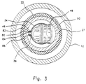
- the perforating and propellant apparatus of the present invention is illustrated generally as 20 and has one end thereof secured to a tandem sub 60 while the other end thereof is secured to a bull plug 66.
- a perforating charge carrier 22 is positioned between tandem sub 60 and bull plug 66 and is secured thereto by any suitable means, such as by mating screw threads 23 and 24 which are provided in the internal surface of carrier 22 adjacent each end thereof with corresponding threads 61 and 67 of tandem sub 60 and bull plug 66, respectively.
- O-rings 70 provide a fluid tight seal between carrier 22 and tandem sub 60 while O-rings 74 provide a fluid tight seal between carrier 22 and bull plug 66.
- Carrier 22 may be a commercially available carrier for perforating charges and contains at least one conventional perforating charge 40 capable of creating an aperture in the carrier wall 30, well casing 12, and a portion of the adjacent subterranean formation 16.
- a perforating charge tube 34 is positioned within carrier 22 and has at least one relatively large aperture or opening 35 and a plurality of smaller apertures or openings 36 therein. Openings 35 in the wall of charge tube 34 may be spaced both vertically along and angularly about the axis of the tube.
- Charge carrier 22 and perforating charge tube 34 have generally elongated tubular configurations.
- a lined perforating charge 40 has a small end 46 secured in an aperture or opening 36 in perforating charge tube 34, as described below, and a large end 48 aligned with and protruding through opening or aperture 35 in tube 34. At least one lined perforating charge 40 is mounted in perforating charge tube 34.
- a detonating cord 86 is connected to a detonator above tandem sub 60, to the small end 46 of each perforating charge 40, and to end cap 68 in bull plug 66.
- Tube alignment end plates 50 function to align charge tube 34 within carrier 22 so that the front of each charge is adjacent a scallop 27 in the wall of carrier 22.
- charge density is an appropriate density determined by methods known to those skilled in the art. Common charge densities range between two and twenty four per foot
- Detonating cord 86 connects a booster transfer (not illustrated) in tandem sub 60 above carrier 22, all charges 40, and end cap 68 in bull plug 66.
- brackets 80 on the small end 46 of lined perforating charge 40 extend through opening 36 in charge tube 34.
- a clip 82 secures punch charge 40 to charge tube 34.
- Detonating cord 86 is threaded through a space 84 between brackets 80 and clip 82.
- Charge tube 34 is mounted in carrier 22 so that the small end 46 of charge 40 is adjacent scallop 27 in carrier 22.
- a typical perforating charge is illustrated generally as 40.
- a highly compressed explosive 41 partially fills perforating charge case 42.
- Liner 43 covers the exposed surface of the explosive.
- the liner 43 is commonly metallic and serves to focus the energy of the charge and enable the charge to perforate a well casing.
- a sleeve 90 which has a generally tubular configuration (FIG. 5) is positioned around perforating charge carrier 22 during manufacture of the perforating and propellant apparatus 20 of the present invention or during final assembly thereof which may take place at the well site.
- sleeve 90 As assembled (FIG. 2), sleeve 90 is secured in positioned around perforating charge carrier 22 at one end by tandem sub 60 and by bull plug 66 at the other end. Tandem sub 60 and bull plug 66 may be sized to have an external diameter greater than sleeve 90 so as to inhibit damage to sleeve 90 during positioning within a well bore.
- protective rings or the like which have a larger external diameter than sleeve 90 may be inserted between tandem sub 60, bull plug 66 and sleeve 90 during manufacture or final assembly of the apparatus of the present invention so as to inhibit damage to sleeve 90.
- Sleeve 90 may extend the entire distance between tandem sub 60 and bull plug 66 or a portion thereof.
- Sleeve 90 is constructed of a water repellant or water proof propellant material which is not physically effected by hydrostatic pressures commonly observed during perforation of a subterranean formation(s) and is unreactive or inert to almost all fluids, in particular those fluids encountered in a subterranean well bore.
- the propellant is a cured epoxy or plastic having an oxidizer incorporated therein such as that commercially available from HTH Technical Services, Inc. of Coeur d'Alene, Idaho.
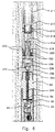
- Vent housing 210 is capable of attachment to the end of a tubing string 211 or wireline (not shown).
- a vent 212 is attached to connecting rod 214 inside vent housing 210 and seals fluid passage 216.
- Rod 214 is in contact with a piston 218.
- An annular chamber 220 between piston 218 and the interior wall of housing 210 is filled with air at atmospheric pressure. Adjacent the bottom of piston 218, shear pins 222 are mounted in shear set 224, and a firing pin 226 extends downward from the bottom of piston 218.
- Retainer 228 joins vent housing 200 and tandem sub 60.
- Percussion detonator 230 is mounted in retainer 228 in firing head 236 which is attached to vent housing 210 and capable of attachment to tandem sub 60.
- Sub 60 is attached to perforating charge carrier 22.
- An ignition transfer 232 at the top of sub 60 is in contact with detonating cord 86 passing through central channel 234 and charge carrier 22, as described above.
- a booster transfer is located in each tandem sub 60, linking the detonating cords in the charge carriers above and below the tandem sub.
- detonating cord 86 comprises an explosive and runs between the ends of each charge carrier, passing between the backs of the charges and the charge clips holding the charges in the carrier. Cord 86 ignites the shaped charges 40 in charge carrier 22 and booster transfer, which contains a higher grade explosive than detonating cord 86.
- an impact detonator provides a primary detonation.
- the primary detonator could, alternatively, be an electrical detonator.
- the primary detonator ignites a pressure-sensitive chemical in ignition transfer 232, which in tum ignites detonating cord.
- the detonating cord then ignites the one or more charges 40 in the carrier 22 simultaneously.
- Each transfer booster also contains an explosive for detonating the cord 86 in the adjacent carrier.
- the system may be detonated from the top, the bottom, or both.
- the desired number of perforating charge carriers 22 are loaded with charges 40 and are connected with a detonating means, such as detonating cord 86.
- a string of apparatus 20 separated by tandem subs 60 is assembled at the well site as the units are lowered into well 10 at the end of a tubing string, wireline, slick line, coil tubing or any other suitable means as will be evident to a skilled artisan.
- Propellant sleeve 90 may be cut from a length of propellant tubular and positioned around perforating charge carrier 22 at the well site.
- the apparatus 20 is then located in the well with the perforating charges adjacent the formation interval 16 to be perforated.
- the perforating charges 40 are then detonated.
- each perforating charge 40 blasts through a scallop 27 in carrier 32, penetrates propellant sleeve 90, creates an opening in casing 12 and penetrates formation 16 forming perforations therein.
- Propellant sleeve 90 breaks apart and ignites due to the shock, heat, and pressure of the detonated shaped charge 40.
- pressurized gas generated from the burning of propellant sleeve 90 enters formation 16 through the recently formed perforations thereby cleaning such perforations of debris.
- These propellant gases also stimulate formation 16 by extending the connectivity of formation 16 with well 10 by means of the pressure of the propellant gases fracturing the formation.
- a proppant such as sand
- sand may be introduced into well 10 almost simultaneously with the ignition of the perforation and propellant apparatus 20 of the present invention by any of a variety of suitable means, such as a conventional perforating charge carrier which is equipped with punch charges filled with sand and connected in series to detonating cord 86, as is commercially available under the trademark POWR PERF from Halliburton Energy Services or Advance Completion Technologies Inc.
- gases generated by burning propellant sleeve 90 escape from the well and enter the perforations formed in formation 16
- the sand which is carried into the fractures by the propellant gases abrades or scours the walls of the perforations and fractures, thereby enlarging the conduits for fluid flow between the formation and the well 10.
- Some of the sand may remain in the fractures as a proppant, thereby preventing the fractures from closing when the fluid pressure is relieved.
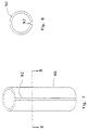
- sleeve 90 may be provided with one or more grooves or slits 92 which may extend through the entire thickness of sleeve 90 (FIG. 7) and which may extend substantially the entire length thereof.
- the slit(s) is positioned adjacent a shaped charge 40 such that upon ignition shaped charge 40 impacts slit 92 which provides a greater surface area for sleeve 90 to ignite and burn.
- slit(s) 92 is tapered (FIG. 8) such that the slit is wider at the internal surface of sleeve 90 than the external surface thereof.
- the internal surface of sleeve 90 may be provided with grooves or channels 94 (FIGS. 9 and 10) to assist in propellant sleeve 90 uniformly breaking upon being impacted by shaped charge 40.
- Grooves or channels 94 may have a varied or a uniform thickness or depth and may be formed in a uniform or random pattern.
- carrier 122 is constructed of a water repellant or proof propellant material which is not physically effected by hydrostatic pressures commonly observed during perforation or subterranean formations and is unreactive or inert to almost all fluids, in particular those fluids encountered in a subterranean well bore.
- the propellant is a cured epoxy, carbon fiber composite having an oxidizer incorporated therein such as that commercially available from HTH Technical Services, Inc. of Coeur d'Alene, Idaho.
- Carrier 122 contains at least one conventional perforating charge 140 capable of creating an aperture in the carrier wall 130, well casing 12, and a portion of the interval 16 in the adjacent subterranean formation.
- Each perforating charge 140 is secured in an opening 136 in perforating charge tube 134 with a clip.
- tandem sub 160, bull plug 166 and charge tube 134 are constructed of a material which substantially entirely breaks up or decomposes, for example thin walled steel, a material which substantially disintegrates, for example a carbon fiber, epoxy composite, upon detonation of charges 140, or a material which is completely bumable, such as a epoxy, oxidizer propellant similar to that used for sleeve 90..
- Detonating cord 186 connects a booster transfer in tandem sub 160 above carrier 122, all charges 40, and end cap 168 in bull plug 166. As previously discussed with respect to the embodiment illustrated in FIG. 2, one or more combinations of an additional tandem sub and an additional perforating charge carrier could be mounted below carrier 122. The detonating cord 186 would then be connected to a booster transfer in the tandem sub 160 below each additional perforating charge carrier.
- a 36 inch long, 4 inch outer diameter, 3.4375 inch inner diameter sleeve of cured epoxy having an oxidizer incorporated therein is positioned around a 3 foot long, 3.375 inch outer diameter perforating gun.
- This perforating gun has 4 shaped charges per foot, 60 degree phasing of the charges and a scalloped carrier.
- the perforating gun which is equipped with the propellant sleeve is run into a subterranean well and is positioned by means of wireline to perforate a 3 feet interval at about 3630 feet.
- a fast pressure gauge is also run. After logging on depth, 50 barrels of water are pumped into the well and the apparatus is ignited. The wireline is noted not to jump.
- the propellant sleeve Upon retrieval, the propellant sleeve is missing from the perforating gun and analysis of the fast gauge pressure data indicates that a high pressure pulse is sustained for 5 milliseconds compared to approximately 7 microseconds which is achievable with a conventional perforating gun.
- the perforating and propellant apparatus of the present invention can be utilized with tubing or wiretine.
- the increased strength of the tubing over wireline allows the use of a longer perforating and propellant apparatus, thereby allowing a longer interval to be perforated and stimulated in a single trip into a well.
- a tubing-conveyed apparatus is also compatible with the use of packers to isolate one or more portions of the well adjacent one or more intervals of the formation.
- the method may be used where it is desired for some other reason to limit the pressure to which another portion of the well is subjected, for example, in a well where one or more other zones have already been completed.
- the tubing may be used to push the perforating and propellant apparatus into the well.
- Multiple intervals of a subterranean formation can be perforated and fractured in a single operation by combining two or more perforating and propellant apparatus 20 and/or 120 of the present invention with a single tubing string in a spaced apart manner as will be evident to a skilled artisan.
- shaped charges containing a smaller amount of highly compressed explosive than conventional charges may be employed since the shaped charge need only perforate casing 12 as gases which are generated by burning propellant extend the perforation and fractures into the subterranean formation.
- propellant sleeve 90 or carrier 122 may have proppant dispersed throughout or embedded upon the outer surface thereof. This proppant may also contain a radioactive tag to assist in determining the dispersion of the proppant into the perforations in the subterranean formation(s).
- the various embodiments of the apparatus of the present invention have been described and illustrated as being comprised of several component parts which are secured together in a fluid tight relationship, it is within the scope of the present invention to construct the apparatus 20 or 120 of an integral piece of propellant material which is open to flow of fluids from the well bore and in which shaped charges are secured.
Landscapes
- Life Sciences & Earth Sciences (AREA)
- Engineering & Computer Science (AREA)
- Geology (AREA)
- Mining & Mineral Resources (AREA)
- Physics & Mathematics (AREA)
- Environmental & Geological Engineering (AREA)
- Fluid Mechanics (AREA)
- General Life Sciences & Earth Sciences (AREA)
- Geochemistry & Mineralogy (AREA)
- Drilling And Exploitation, And Mining Machines And Methods (AREA)
- Massaging Devices (AREA)
- Electrotherapy Devices (AREA)
Claims (11)
- Vorrichtung (20, 120) zur Durchlochung und Stimulierung einer Untergrundformation (16) mit einer oder mehreren Sprengsätzen (40, 140) und einem Sprengzünder (230), der mit dem einen oder mehreren Sprengsätzen verbunden ist, gekennzeichnet durch eine aus Treibmittel gebaute Schale (90, 122), wobei der eine oder die mehreren Sprengsätze in der Treibmittelschale angeordnet sind.
- Vorrichtung nach Anspruch 1, bei der die Schale eine Hülse (90, 120) ist.
- Vorrichtung nach Anspruch 2, bei der die Hülse (90) wenigstens eine Nut (92, 92) darin hat.
- Vorrichtung nach Anspruch 1, bei der die eine oder mehreren Ladungen in einem Träger (122) befestigt sind, welcher aus einem Material gebaut ist, das bei einer Detonation des einen oder der mehreren Sprengsätze zerfällt oder sich zersetzt.
- Vorrichtung nach Anspruch 1, bei der das Treibmittel wasserabstoßend oder wasserundurchlässig ist, durch hydrostatische Drücke, die in der Untergrundformation (16) auftreten, physikalisch nicht beeinflußt wird und nicht reaktiv oder inert gegenüber Fluiden ist, welche in einem Schacht (10) auftreten können, der die Untergrundformation durchdringt und in Fluidverbindung mit ihr steht.
- Vorrichtung nach Anspruch 5, bei der das Treibmittel ein gehärteten Epoxyharz oder ein gehärteter Kunststoff mit einem Oxidationsmittel darin ist.
- Verfahren zum Durchlochen und Stimulieren einer Untergrundformation (16), welche von einer Schachtbohrung (10) durchdrungen ist, mit einem Gehäuse (12), das darin so angeordnet ist, daß man eine Fluidverbindung zwischen der Formation und der Schachtbohrung bekommt, wobei das Verfahren das Sprengen einer Durchlochungsladung (40, 140) in der Schachtbohrung und ein Durchlochen des Gehäuses umfaßt, dadurch gekennzeichnet, daß man ein Treibmittelmaterial (90, 122), welches zwischen der durchlochenden Sprengladung (40, 140) und dem Gehäuse (12) eingeschaltet ist, durch Detonation der durchlochenden Ladung zündet.
- Kit für eine Vorrichtung (20, 120) zum Durchlochen und Stimulieren einer Untergrundformation (16) mit einer Vorrichtung (20, 120) zur Durchlochung einer Untergrundformation, welche wenigstens eine geformte Ladung (940, 140) hat, dadurch gekennzeichnet, daß eine Hülse (90, 122), die aus Trelbmittel aufgebaut ist, das daran angepaßt ist, um die Vorrichtung herum positioniert wird.
- Kit nach Anspruch 8, bei dem die Hülse (90) einen Schlitz (92) hat
- Kit nach Anspruch 9, bei dem die Länge der Hülse (90, 122) im wesentlichen die gleiche wie die Länge der Vorrichtung (20, 120) ist.
- Kit nach Anspruch 9, bei dem die Lange der Hülse (90) kürzer als die Länge der Vorrichtung (20) ist.
Applications Claiming Priority (3)
| Application Number | Priority Date | Filing Date | Title |
|---|---|---|---|
| US711188 | 1996-09-09 | ||
| US08/711,188 US5775426A (en) | 1996-09-09 | 1996-09-09 | Apparatus and method for perforating and stimulating a subterranean formation |
| PCT/US1997/012594 WO1998010167A1 (en) | 1996-09-09 | 1997-07-28 | Apparatus and method for perforating and stimulating a subterranean formation |
Publications (3)
| Publication Number | Publication Date |
|---|---|
| EP0925423A1 EP0925423A1 (de) | 1999-06-30 |
| EP0925423A4 EP0925423A4 (de) | 2000-12-13 |
| EP0925423B1 true EP0925423B1 (de) | 2003-11-12 |
Family
ID=24857101
Family Applications (1)
| Application Number | Title | Priority Date | Filing Date |
|---|---|---|---|
| EP97935002A Expired - Lifetime EP0925423B1 (de) | 1996-09-09 | 1997-07-28 | Vorrichtung und verfahren zum perforieren und stimulieren einer gesteinsformation |
Country Status (10)
| Country | Link |
|---|---|
| US (1) | US5775426A (de) |
| EP (1) | EP0925423B1 (de) |
| CN (1) | CN1080365C (de) |
| AU (1) | AU3804097A (de) |
| BR (1) | BR9711603A (de) |
| CA (1) | CA2251639C (de) |
| DE (1) | DE69726161D1 (de) |
| EA (1) | EA000780B1 (de) |
| NO (1) | NO318134B1 (de) |
| WO (1) | WO1998010167A1 (de) |
Cited By (2)
| Publication number | Priority date | Publication date | Assignee | Title |
|---|---|---|---|---|
| US9476289B2 (en) | 2013-09-12 | 2016-10-25 | G&H Diversified Manufacturing Lp | In-line adapter for a perforating gun |
| WO2022192541A1 (en) * | 2021-03-12 | 2022-09-15 | Schlumberger Technology Corporation | Shaped charge integrated canister |
Families Citing this family (110)
| Publication number | Priority date | Publication date | Assignee | Title |
|---|---|---|---|---|
| US6082450A (en) * | 1996-09-09 | 2000-07-04 | Marathon Oil Company | Apparatus and method for stimulating a subterranean formation |
| US6158511A (en) * | 1996-09-09 | 2000-12-12 | Marathon Oil Company | Apparatus and method for perforating and stimulating a subterranean formation |
| US5894888A (en) * | 1997-08-21 | 1999-04-20 | Chesapeake Operating, Inc | Horizontal well fracture stimulation methods |
| US5960894A (en) * | 1998-03-13 | 1999-10-05 | Primex Technologies, Inc. | Expendable tubing conveyed perforator |
| US6223656B1 (en) * | 1998-05-15 | 2001-05-01 | The Regents Of The University Of California | Pressure enhanced penetration with shaped charge perforators |
| US6138753A (en) * | 1998-10-30 | 2000-10-31 | Mohaupt Family Trust | Technique for treating hydrocarbon wells |
| FR2793279B1 (fr) | 1999-05-05 | 2001-06-29 | Total Sa | Procede et dispositif pour traiter les perforations d'un puits |
| GB0102914D0 (en) * | 2001-02-06 | 2001-03-21 | Secr Defence Brit | Oil well perforator |
| CA2446888C (en) * | 2001-02-06 | 2008-06-17 | Xi'an Tongyuan Petrotech Co., Ltd. | A high-energy combined well perforating device |
| US6497285B2 (en) | 2001-03-21 | 2002-12-24 | Halliburton Energy Services, Inc. | Low debris shaped charge perforating apparatus and method for use of same |
| US20030070811A1 (en) | 2001-10-12 | 2003-04-17 | Robison Clark E. | Apparatus and method for perforating a subterranean formation |
| US6561274B1 (en) | 2001-11-27 | 2003-05-13 | Conoco Phillips Company | Method and apparatus for unloading well tubing |
| US6865978B2 (en) * | 2002-12-05 | 2005-03-15 | Edward C. Kash | Well perforating gun |
| US6865792B2 (en) | 2003-02-18 | 2005-03-15 | Edward Cannoy Kash | Method for making a well perforating gun |
| US7055421B2 (en) * | 2003-02-18 | 2006-06-06 | Edward Cannoy Kash | Well perforating gun |
| US6926096B2 (en) | 2003-02-18 | 2005-08-09 | Edward Cannoy Kash | Method for using a well perforating gun |
| US20040211556A1 (en) * | 2003-04-23 | 2004-10-28 | Choate Truman L. | Packoff subassembly |
| CA2534398A1 (en) * | 2003-07-01 | 2005-01-20 | G & H Diversified Manufacturing, Lp | Well perforating gun related application information |
| US7059411B2 (en) * | 2003-08-29 | 2006-06-13 | Kirby Hayes Incorporated | Process of using a propellant treatment and continuous foam removal of well debris and apparatus therefore |
| US7044225B2 (en) * | 2003-09-16 | 2006-05-16 | Joseph Haney | Shaped charge |
| US7431075B2 (en) * | 2004-10-05 | 2008-10-07 | Schlumberger Technology Corporation | Propellant fracturing of wells |
| US7430965B2 (en) * | 2004-10-08 | 2008-10-07 | Halliburton Energy Services, Inc. | Debris retention perforating apparatus and method for use of same |
| EP1856473A2 (de) * | 2005-02-23 | 2007-11-21 | Dale Seekford | Verfahren und vorrichtung zur bohrlochstimulierung mit treibstoffen |
| US7621332B2 (en) * | 2005-10-18 | 2009-11-24 | Owen Oil Tools Lp | Apparatus and method for perforating and fracturing a subterranean formation |
| US8347962B2 (en) * | 2005-10-27 | 2013-01-08 | Baker Hughes Incorporated | Non frangible perforating gun system |
| US7748457B2 (en) * | 2006-01-13 | 2010-07-06 | Schlumberger Technology Corporation | Injection of treatment materials into a geological formation surrounding a well bore |
| US7540326B2 (en) * | 2006-03-30 | 2009-06-02 | Schlumberger Technology Corporation | System and method for well treatment and perforating operations |
| EP2021578B1 (de) * | 2006-05-26 | 2020-02-26 | Owen Oil Tools LP | Perforationsverfahren und vorrichtungen für hochdruckbohranwendungen |
| US9520219B2 (en) * | 2006-06-06 | 2016-12-13 | Owen Oil Tools Lp | Retention member for perforating guns |
| US7789153B2 (en) * | 2006-10-26 | 2010-09-07 | Alliant Techsystems, Inc. | Methods and apparatuses for electronic time delay and systems including same |
| US7810569B2 (en) * | 2007-05-03 | 2010-10-12 | Baker Hughes Incorporated | Method and apparatus for subterranean fracturing |
| US20090078420A1 (en) * | 2007-09-25 | 2009-03-26 | Schlumberger Technology Corporation | Perforator charge with a case containing a reactive material |
| US7762351B2 (en) * | 2008-10-13 | 2010-07-27 | Vidal Maribel | Exposed hollow carrier perforation gun and charge holder |
| US8286706B2 (en) * | 2009-03-26 | 2012-10-16 | Baker Hughes Incorporated | Pressure compensation for a perforating gun |
| US8522863B2 (en) * | 2009-04-08 | 2013-09-03 | Propellant Fracturing & Stimulation, Llc | Propellant fracturing system for wells |
| RU2459946C2 (ru) * | 2009-06-25 | 2012-08-27 | Ильгиз Фатыхович Садыков | Способ обработки призабойной зоны пласта жидким горюче-окислительным составом |
| US8336437B2 (en) * | 2009-07-01 | 2012-12-25 | Halliburton Energy Services, Inc. | Perforating gun assembly and method for controlling wellbore pressure regimes during perforating |
| US8555764B2 (en) * | 2009-07-01 | 2013-10-15 | Halliburton Energy Services, Inc. | Perforating gun assembly and method for controlling wellbore pressure regimes during perforating |
| US9027667B2 (en) | 2009-11-11 | 2015-05-12 | Tong Oil Tools Co. Ltd. | Structure for gunpowder charge in combined fracturing perforation device |
| CN102052068B (zh) | 2009-11-11 | 2013-04-24 | 西安通源石油科技股份有限公司 | 油气井复合压裂射孔方法及装置 |
| US8381807B2 (en) * | 2009-12-14 | 2013-02-26 | Summit Downhole Dynamics, Ltd. | Hydraulically-actuated propellant stimulation downhole tool |
| US8167044B2 (en) * | 2009-12-16 | 2012-05-01 | Sclumberger Technology Corporation | Shaped charge |
| US8381652B2 (en) | 2010-03-09 | 2013-02-26 | Halliburton Energy Services, Inc. | Shaped charge liner comprised of reactive materials |
| US8734960B1 (en) | 2010-06-17 | 2014-05-27 | Halliburton Energy Services, Inc. | High density powdered material liner |
| US8449798B2 (en) | 2010-06-17 | 2013-05-28 | Halliburton Energy Services, Inc. | High density powdered material liner |
| CN102094613A (zh) | 2010-12-29 | 2011-06-15 | 西安通源石油科技股份有限公司 | 携带支撑剂的复合射孔方法及装置 |
| US8769795B2 (en) | 2011-08-11 | 2014-07-08 | Edward Cannoy Kash | Method for making a rust resistant well perforating gun with gripping surfaces |
| US8851191B2 (en) | 2011-10-18 | 2014-10-07 | Baker Hughes Incorporated | Selectively fired high pressure high temperature back-off tool |
| CN102410006B (zh) | 2011-12-15 | 2014-05-07 | 西安通源石油科技股份有限公司 | 多级复合射孔装置的火药装药结构 |
| US9297242B2 (en) | 2011-12-15 | 2016-03-29 | Tong Oil Tools Co., Ltd. | Structure for gunpowder charge in multi-frac composite perforating device |
| WO2013109985A1 (en) | 2012-01-18 | 2013-07-25 | Owen Oil Tools Lp | System and method for enhanced wellbore perforations |
| US20130206385A1 (en) * | 2012-02-15 | 2013-08-15 | Guofu Feng | Multi-element hybrid perforating apparatus |
| RU2487237C1 (ru) * | 2012-03-20 | 2013-07-10 | Федеральное государственное бюджетное образовательное учреждение высшего профессионального образования "Казанский государственный энергетический университет" (ФГБОУ ВПО "КГЭУ") | Устройство для обработки призабойной зоны скважины и способ обработки призабойной зоны скважины |
| US9145763B1 (en) * | 2012-05-15 | 2015-09-29 | Joseph A. Sites, Jr. | Perforation gun with angled shaped charges |
| US9228738B2 (en) | 2012-06-25 | 2016-01-05 | Orbital Atk, Inc. | Downhole combustor |
| US9291041B2 (en) | 2013-02-06 | 2016-03-22 | Orbital Atk, Inc. | Downhole injector insert apparatus |
| US9494025B2 (en) | 2013-03-01 | 2016-11-15 | Vincent Artus | Control fracturing in unconventional reservoirs |
| US9702680B2 (en) | 2013-07-18 | 2017-07-11 | Dynaenergetics Gmbh & Co. Kg | Perforation gun components and system |
| CA3070118A1 (en) * | 2013-07-18 | 2015-01-18 | Dynaenergetics Gmbh & Co. Kg | Perforation gun components and system |
| US20220258103A1 (en) | 2013-07-18 | 2022-08-18 | DynaEnergetics Europe GmbH | Detonator positioning device |
| RU2659933C2 (ru) | 2013-08-26 | 2018-07-04 | Динаэнергетикс Гмбх Унд Ко. Кг | Модуль баллистической передачи |
| US10188990B2 (en) | 2014-03-07 | 2019-01-29 | Dynaenergetics Gmbh & Co. Kg | Device and method for positioning a detonator within a perforating gun assembly |
| US9453402B1 (en) | 2014-03-12 | 2016-09-27 | Sagerider, Inc. | Hydraulically-actuated propellant stimulation downhole tool |
| MX2016012264A (es) | 2014-03-26 | 2017-04-27 | Superior Energy Services Llc | Métodos de localización y estimulación y aparatos que utilizan herramientas de fondo de pozo. |
| US9896920B2 (en) | 2014-03-26 | 2018-02-20 | Superior Energy Services, Llc | Stimulation methods and apparatuses utilizing downhole tools |
| US9689246B2 (en) | 2014-03-27 | 2017-06-27 | Orbital Atk, Inc. | Stimulation devices, initiation systems for stimulation devices and related methods |
| US9784549B2 (en) | 2015-03-18 | 2017-10-10 | Dynaenergetics Gmbh & Co. Kg | Bulkhead assembly having a pivotable electric contact component and integrated ground apparatus |
| US11293736B2 (en) | 2015-03-18 | 2022-04-05 | DynaEnergetics Europe GmbH | Electrical connector |
| CN107532469B (zh) * | 2015-04-02 | 2020-11-17 | 欧文石油工具有限合伙公司 | 射孔枪 |
| CA2983867A1 (en) * | 2015-05-15 | 2016-11-24 | Sergio F. Goyeneche | Apparatus for electromechanically connecting a plurality of guns for well perforation |
| US9360222B1 (en) | 2015-05-28 | 2016-06-07 | Innovative Defense, Llc | Axilinear shaped charge |
| US10267127B2 (en) * | 2015-08-25 | 2019-04-23 | Owen Oil Tools Lp | EFP detonating cord |
| RU2637267C1 (ru) * | 2016-10-14 | 2017-12-01 | Общество с ограниченной ответственностью "Промперфоратор" | Устройство для перфорации скважин и газодинамического воздействия на пласт |
| NO343254B1 (en) * | 2017-07-05 | 2018-12-27 | Tco As | Gun for oriented perforation |
| RU2683467C1 (ru) * | 2017-11-29 | 2019-03-28 | Марат Ильгизович Садыков | Термоисточник для термогазодинамического разрыва пласта |
| US11408279B2 (en) | 2018-08-21 | 2022-08-09 | DynaEnergetics Europe GmbH | System and method for navigating a wellbore and determining location in a wellbore |
| US11661824B2 (en) | 2018-05-31 | 2023-05-30 | DynaEnergetics Europe GmbH | Autonomous perforating drone |
| US10794159B2 (en) | 2018-05-31 | 2020-10-06 | DynaEnergetics Europe GmbH | Bottom-fire perforating drone |
| US11905823B2 (en) | 2018-05-31 | 2024-02-20 | DynaEnergetics Europe GmbH | Systems and methods for marker inclusion in a wellbore |
| US10458213B1 (en) | 2018-07-17 | 2019-10-29 | Dynaenergetics Gmbh & Co. Kg | Positioning device for shaped charges in a perforating gun module |
| US11591885B2 (en) | 2018-05-31 | 2023-02-28 | DynaEnergetics Europe GmbH | Selective untethered drone string for downhole oil and gas wellbore operations |
| US10386168B1 (en) | 2018-06-11 | 2019-08-20 | Dynaenergetics Gmbh & Co. Kg | Conductive detonating cord for perforating gun |
| US11339614B2 (en) | 2020-03-31 | 2022-05-24 | DynaEnergetics Europe GmbH | Alignment sub and orienting sub adapter |
| USD921858S1 (en) | 2019-02-11 | 2021-06-08 | DynaEnergetics Europe GmbH | Perforating gun and alignment assembly |
| US11808093B2 (en) | 2018-07-17 | 2023-11-07 | DynaEnergetics Europe GmbH | Oriented perforating system |
| US11808098B2 (en) | 2018-08-20 | 2023-11-07 | DynaEnergetics Europe GmbH | System and method to deploy and control autonomous devices |
| US11448044B2 (en) * | 2018-11-29 | 2022-09-20 | Hunting Titan, Inc. | Universal plug and play perforating gun tandem |
| USD1019709S1 (en) | 2019-02-11 | 2024-03-26 | DynaEnergetics Europe GmbH | Charge holder |
| USD1010758S1 (en) | 2019-02-11 | 2024-01-09 | DynaEnergetics Europe GmbH | Gun body |
| CN113646505A (zh) | 2019-04-01 | 2021-11-12 | 德力能欧洲有限公司 | 可回收的射孔枪组件和部件 |
| US11578549B2 (en) | 2019-05-14 | 2023-02-14 | DynaEnergetics Europe GmbH | Single use setting tool for actuating a tool in a wellbore |
| US10927627B2 (en) | 2019-05-14 | 2021-02-23 | DynaEnergetics Europe GmbH | Single use setting tool for actuating a tool in a wellbore |
| US11255147B2 (en) | 2019-05-14 | 2022-02-22 | DynaEnergetics Europe GmbH | Single use setting tool for actuating a tool in a wellbore |
| CN114174632A (zh) | 2019-07-19 | 2022-03-11 | 德力能欧洲有限公司 | 弹道致动的井筒工具 |
| US11946728B2 (en) | 2019-12-10 | 2024-04-02 | DynaEnergetics Europe GmbH | Initiator head with circuit board |
| WO2021122797A1 (en) | 2019-12-17 | 2021-06-24 | DynaEnergetics Europe GmbH | Modular perforating gun system |
| US11225848B2 (en) | 2020-03-20 | 2022-01-18 | DynaEnergetics Europe GmbH | Tandem seal adapter, adapter assembly with tandem seal adapter, and wellbore tool string with adapter assembly |
| USD981345S1 (en) | 2020-11-12 | 2023-03-21 | DynaEnergetics Europe GmbH | Shaped charge casing |
| US11988049B2 (en) | 2020-03-31 | 2024-05-21 | DynaEnergetics Europe GmbH | Alignment sub and perforating gun assembly with alignment sub |
| USD904475S1 (en) | 2020-04-29 | 2020-12-08 | DynaEnergetics Europe GmbH | Tandem sub |
| USD908754S1 (en) | 2020-04-30 | 2021-01-26 | DynaEnergetics Europe GmbH | Tandem sub |
| US20220018224A1 (en) * | 2020-07-20 | 2022-01-20 | Geodynamics, Inc. | Multi-layer loading tube for perforating gun |
| US11377936B2 (en) * | 2020-08-12 | 2022-07-05 | Baker Hughes Oilfield Operations Llc | Cartridge system and method for setting a tool |
| CA3206497A1 (en) | 2021-02-04 | 2022-08-11 | Christian EITSCHBERGER | Perforating gun assembly with performance optimized shaped charge load |
| US11499401B2 (en) | 2021-02-04 | 2022-11-15 | DynaEnergetics Europe GmbH | Perforating gun assembly with performance optimized shaped charge load |
| US11713625B2 (en) | 2021-03-03 | 2023-08-01 | DynaEnergetics Europe GmbH | Bulkhead |
| US11732556B2 (en) | 2021-03-03 | 2023-08-22 | DynaEnergetics Europe GmbH | Orienting perforation gun assembly |
| US11761279B2 (en) * | 2021-05-06 | 2023-09-19 | Innovex Downhole Solutions, Inc. | Multi-stage propellant charge for downhole setting tools |
| NO346353B1 (en) | 2021-05-11 | 2022-06-20 | Archer Oiltools As | Toolstring and method for inner casing perforating, shattering annulus cement, and washing the first annulus in a second casing, and cementing said annulus, and a tool therefor |
| US11753889B1 (en) | 2022-07-13 | 2023-09-12 | DynaEnergetics Europe GmbH | Gas driven wireline release tool |
Family Cites Families (21)
| Publication number | Priority date | Publication date | Assignee | Title |
|---|---|---|---|---|
| US3029732A (en) * | 1959-05-18 | 1962-04-17 | Haskell M Greene | Perforation and cleaning of wells |
| US3064733A (en) * | 1959-10-29 | 1962-11-20 | Continental Oil Co | Apparatus and method for completing wells |
| US3366188A (en) * | 1965-06-28 | 1968-01-30 | Dresser Ind | Burr-free shaped charge perforating |
| US3376375A (en) * | 1965-10-23 | 1968-04-02 | Dresser Ind | Combined propellant charge and bullet unit for well |
| US4039030A (en) * | 1976-06-28 | 1977-08-02 | Physics International Company | Oil and gas well stimulation |
| US4191265A (en) * | 1978-06-14 | 1980-03-04 | Schlumberger Technology Corporation | Well bore perforating apparatus |
| US4253523A (en) * | 1979-03-26 | 1981-03-03 | Ibsen Barrie G | Method and apparatus for well perforation and fracturing operations |
| US4391337A (en) * | 1981-03-27 | 1983-07-05 | Ford Franklin C | High-velocity jet and propellant fracture device for gas and oil well production |
| US4541486A (en) * | 1981-04-03 | 1985-09-17 | Baker Oil Tools, Inc. | One trip perforating and gravel pack system |
| US4598775A (en) * | 1982-06-07 | 1986-07-08 | Geo. Vann, Inc. | Perforating gun charge carrier improvements |
| US4502550A (en) * | 1982-12-06 | 1985-03-05 | Magnum Jet, Inc. | Modular through-tubing casing gun |
| US4823875A (en) * | 1984-12-27 | 1989-04-25 | Mt. Moriah Trust | Well treating method and system for stimulating recovery of fluids |
| US4633951A (en) * | 1984-12-27 | 1987-01-06 | Mt. Moriah Trust | Well treating method for stimulating recovery of fluids |
| US4683943A (en) * | 1984-12-27 | 1987-08-04 | Mt. Moriah Trust | Well treating system for stimulating recovery of fluids |
| US4823876A (en) * | 1985-09-18 | 1989-04-25 | Mohaupt Henry H | Formation stimulating tool with anti-acceleration provisions |
| US4711302A (en) * | 1986-08-25 | 1987-12-08 | Mobil Oil Corporation | Gravel pack void space removal via high energy impulse |
| US5005641A (en) * | 1990-07-02 | 1991-04-09 | Mohaupt Henry H | Gas generator with improved ignition assembly |
| US5355802A (en) * | 1992-11-10 | 1994-10-18 | Schlumberger Technology Corporation | Method and apparatus for perforating and fracturing in a borehole |
| US5421418A (en) * | 1994-06-28 | 1995-06-06 | Schlumberger Technology Corporation | Apparatus and method for mixing polyacrylamide with brine in an annulus of a wellbore to prevent a cement-like mixture from fouling wellbore tools |
| US5598891A (en) * | 1994-08-04 | 1997-02-04 | Marathon Oil Company | Apparatus and method for perforating and fracturing |
| US5477785A (en) * | 1995-01-27 | 1995-12-26 | The Ensign-Bickford Company | Well pipe perforating gun |
-
1996
- 1996-09-09 US US08/711,188 patent/US5775426A/en not_active Expired - Lifetime
-
1997
- 1997-07-28 EA EA199800708A patent/EA000780B1/ru not_active IP Right Cessation
- 1997-07-28 AU AU38040/97A patent/AU3804097A/en not_active Abandoned
- 1997-07-28 BR BR9711603A patent/BR9711603A/pt not_active IP Right Cessation
- 1997-07-28 DE DE69726161T patent/DE69726161D1/de not_active Expired - Lifetime
- 1997-07-28 EP EP97935002A patent/EP0925423B1/de not_active Expired - Lifetime
- 1997-07-28 CN CN97195781A patent/CN1080365C/zh not_active Expired - Lifetime
- 1997-07-28 CA CA002251639A patent/CA2251639C/en not_active Expired - Lifetime
- 1997-07-28 WO PCT/US1997/012594 patent/WO1998010167A1/en active IP Right Grant
-
1998
- 1998-11-24 NO NO19985485A patent/NO318134B1/no unknown
Cited By (2)
| Publication number | Priority date | Publication date | Assignee | Title |
|---|---|---|---|---|
| US9476289B2 (en) | 2013-09-12 | 2016-10-25 | G&H Diversified Manufacturing Lp | In-line adapter for a perforating gun |
| WO2022192541A1 (en) * | 2021-03-12 | 2022-09-15 | Schlumberger Technology Corporation | Shaped charge integrated canister |
Also Published As
| Publication number | Publication date |
|---|---|
| BR9711603A (pt) | 1999-08-24 |
| EA000780B1 (ru) | 2000-04-24 |
| NO985485D0 (no) | 1998-11-24 |
| NO985485L (no) | 1999-03-05 |
| DE69726161D1 (de) | 2003-12-18 |
| WO1998010167A1 (en) | 1998-03-12 |
| CA2251639A1 (en) | 1998-03-12 |
| EA199800708A1 (ru) | 1999-08-26 |
| AU3804097A (en) | 1998-03-26 |
| NO318134B1 (no) | 2005-02-07 |
| US5775426A (en) | 1998-07-07 |
| CN1222950A (zh) | 1999-07-14 |
| EP0925423A1 (de) | 1999-06-30 |
| CN1080365C (zh) | 2002-03-06 |
| EP0925423A4 (de) | 2000-12-13 |
| CA2251639C (en) | 2002-06-11 |
Similar Documents
| Publication | Publication Date | Title |
|---|---|---|
| EP0925423B1 (de) | Vorrichtung und verfahren zum perforieren und stimulieren einer gesteinsformation | |
| US6336506B2 (en) | Apparatus and method for perforating and stimulating a subterranean formation | |
| US6263283B1 (en) | Apparatus and method for generating seismic energy in subterranean formations | |
| EP1068426B1 (de) | Vorrichtung und verfahren zur stimulierung von unterirdischen formationen | |
| US7228906B2 (en) | Propellant ignition assembly and process | |
| US7303017B2 (en) | Perforating gun assembly and method for creating perforation cavities | |
| US5598891A (en) | Apparatus and method for perforating and fracturing | |
| EP1761681B1 (de) | Perforatoranordnung und verfahren zur verbesserung der perforationstiefe | |
| EP1875040B1 (de) | Stimulationsgerät mit versiegeltem zündsystem | |
| US5690171A (en) | Wellbore stimulation and completion | |
| EP3397835A1 (de) | System und verfahren zur perforation eines bohrloches | |
| RU51397U1 (ru) | Устройство для вторичного вскрытия с одновременной газодинамической обработки пласта | |
| MXPA01000007A (en) | Apparatus and method for perforating and stimulating a subterranean formation | |
| GB2320272A (en) | Apparatus and method for perforating and fracturing |
Legal Events
| Date | Code | Title | Description |
|---|---|---|---|
| PUAI | Public reference made under article 153(3) epc to a published international application that has entered the european phase |
Free format text: ORIGINAL CODE: 0009012 |
|
| 17P | Request for examination filed |
Effective date: 19981202 |
|
| AK | Designated contracting states |
Kind code of ref document: A1 Designated state(s): DE FR GB IE NL |
|
| A4 | Supplementary search report drawn up and despatched |
Effective date: 20001031 |
|
| AK | Designated contracting states |
Kind code of ref document: A4 Designated state(s): DE FR GB IE NL |
|
| RIC1 | Information provided on ipc code assigned before grant |
Free format text: 7E 21B 43/117 A, 7E 21B 43/267 B, 7E 21B 43/263 B |
|
| 17Q | First examination report despatched |
Effective date: 20020829 |
|
| GRAH | Despatch of communication of intention to grant a patent |
Free format text: ORIGINAL CODE: EPIDOS IGRA |
|
| GRAS | Grant fee paid |
Free format text: ORIGINAL CODE: EPIDOSNIGR3 |
|
| GRAA | (expected) grant |
Free format text: ORIGINAL CODE: 0009210 |
|
| AK | Designated contracting states |
Kind code of ref document: B1 Designated state(s): DE FR GB IE NL |
|
| REG | Reference to a national code |
Ref country code: GB Ref legal event code: FG4D |
|
| REF | Corresponds to: |
Ref document number: 69726161 Country of ref document: DE Date of ref document: 20031218 Kind code of ref document: P |
|
| REG | Reference to a national code |
Ref country code: IE Ref legal event code: FG4D |
|
| PG25 | Lapsed in a contracting state [announced via postgrant information from national office to epo] |
Ref country code: DE Free format text: LAPSE BECAUSE OF FAILURE TO SUBMIT A TRANSLATION OF THE DESCRIPTION OR TO PAY THE FEE WITHIN THE PRESCRIBED TIME-LIMIT Effective date: 20040213 |
|
| ET | Fr: translation filed | ||
| PLBE | No opposition filed within time limit |
Free format text: ORIGINAL CODE: 0009261 |
|
| STAA | Information on the status of an ep patent application or granted ep patent |
Free format text: STATUS: NO OPPOSITION FILED WITHIN TIME LIMIT |
|
| 26N | No opposition filed |
Effective date: 20040813 |
|
| PGFP | Annual fee paid to national office [announced via postgrant information from national office to epo] |
Ref country code: IE Payment date: 20041223 Year of fee payment: 8 |
|
| PG25 | Lapsed in a contracting state [announced via postgrant information from national office to epo] |
Ref country code: IE Free format text: LAPSE BECAUSE OF NON-PAYMENT OF DUE FEES Effective date: 20050728 |
|
| REG | Reference to a national code |
Ref country code: IE Ref legal event code: MM4A |
|
| PGFP | Annual fee paid to national office [announced via postgrant information from national office to epo] |
Ref country code: FR Payment date: 20060705 Year of fee payment: 10 |
|
| REG | Reference to a national code |
Ref country code: FR Ref legal event code: ST Effective date: 20080331 |
|
| PG25 | Lapsed in a contracting state [announced via postgrant information from national office to epo] |
Ref country code: FR Free format text: LAPSE BECAUSE OF NON-PAYMENT OF DUE FEES Effective date: 20070731 |
|
| PGFP | Annual fee paid to national office [announced via postgrant information from national office to epo] |
Ref country code: GB Payment date: 20160624 Year of fee payment: 20 |
|
| PGFP | Annual fee paid to national office [announced via postgrant information from national office to epo] |
Ref country code: NL Payment date: 20160708 Year of fee payment: 20 |
|
| REG | Reference to a national code |
Ref country code: NL Ref legal event code: MK Effective date: 20170727 |
|
| REG | Reference to a national code |
Ref country code: GB Ref legal event code: PE20 Expiry date: 20170727 |
|
| PG25 | Lapsed in a contracting state [announced via postgrant information from national office to epo] |
Ref country code: GB Free format text: LAPSE BECAUSE OF EXPIRATION OF PROTECTION Effective date: 20170727 |