EP0925051B1 - Applicateur souple pour insertion vaginale ou rectale d'un article, comme un tampon - Google Patents
Applicateur souple pour insertion vaginale ou rectale d'un article, comme un tampon Download PDFInfo
- Publication number
- EP0925051B1 EP0925051B1 EP98930348A EP98930348A EP0925051B1 EP 0925051 B1 EP0925051 B1 EP 0925051B1 EP 98930348 A EP98930348 A EP 98930348A EP 98930348 A EP98930348 A EP 98930348A EP 0925051 B1 EP0925051 B1 EP 0925051B1
- Authority
- EP
- European Patent Office
- Prior art keywords
- flexible
- applicator
- structural member
- flex
- enhancing elements
- Prior art date
- Legal status (The legal status is an assumption and is not a legal conclusion. Google has not performed a legal analysis and makes no representation as to the accuracy of the status listed.)
- Expired - Lifetime
Links
Images


Classifications
-
- A—HUMAN NECESSITIES
- A61—MEDICAL OR VETERINARY SCIENCE; HYGIENE
- A61F—FILTERS IMPLANTABLE INTO BLOOD VESSELS; PROSTHESES; DEVICES PROVIDING PATENCY TO, OR PREVENTING COLLAPSING OF, TUBULAR STRUCTURES OF THE BODY, e.g. STENTS; ORTHOPAEDIC, NURSING OR CONTRACEPTIVE DEVICES; FOMENTATION; TREATMENT OR PROTECTION OF EYES OR EARS; BANDAGES, DRESSINGS OR ABSORBENT PADS; FIRST-AID KITS
- A61F13/00—Bandages or dressings; Absorbent pads
- A61F13/15—Absorbent pads, e.g. sanitary towels, swabs or tampons for external or internal application to the body; Supporting or fastening means therefor; Tampon applicators
- A61F13/20—Tampons, e.g. catamenial tampons; Accessories therefor
- A61F13/26—Means for inserting tampons, i.e. applicators
-
- Y—GENERAL TAGGING OF NEW TECHNOLOGICAL DEVELOPMENTS; GENERAL TAGGING OF CROSS-SECTIONAL TECHNOLOGIES SPANNING OVER SEVERAL SECTIONS OF THE IPC; TECHNICAL SUBJECTS COVERED BY FORMER USPC CROSS-REFERENCE ART COLLECTIONS [XRACs] AND DIGESTS
- Y10—TECHNICAL SUBJECTS COVERED BY FORMER USPC
- Y10T—TECHNICAL SUBJECTS COVERED BY FORMER US CLASSIFICATION
- Y10T156/00—Adhesive bonding and miscellaneous chemical manufacture
- Y10T156/10—Methods of surface bonding and/or assembly therefor
- Y10T156/1002—Methods of surface bonding and/or assembly therefor with permanent bending or reshaping or surface deformation of self sustaining lamina
- Y10T156/1007—Running or continuous length work
- Y10T156/1008—Longitudinal bending
- Y10T156/1013—Longitudinal bending and edge-joining of one piece blank to form tube
-
- Y—GENERAL TAGGING OF NEW TECHNOLOGICAL DEVELOPMENTS; GENERAL TAGGING OF CROSS-SECTIONAL TECHNOLOGIES SPANNING OVER SEVERAL SECTIONS OF THE IPC; TECHNICAL SUBJECTS COVERED BY FORMER USPC CROSS-REFERENCE ART COLLECTIONS [XRACs] AND DIGESTS
- Y10—TECHNICAL SUBJECTS COVERED BY FORMER USPC
- Y10T—TECHNICAL SUBJECTS COVERED BY FORMER US CLASSIFICATION
- Y10T156/00—Adhesive bonding and miscellaneous chemical manufacture
- Y10T156/10—Methods of surface bonding and/or assembly therefor
- Y10T156/1002—Methods of surface bonding and/or assembly therefor with permanent bending or reshaping or surface deformation of self sustaining lamina
- Y10T156/1036—Bending of one piece blank and joining edges to form article
Definitions
- the present invention relates to flexible devices for vaginally or rectally inserting an article, like a catamenial tampon,
- the insertion device has an elongate, hollow structural member which has a plurality of flex-enhancing elements which increase its lateral flexibility.
- Hollow insertion devices such as tampon applicators, are generally constructed of one of two basic materials: plastic and cardboard. While cardboard applicators are generally more rigid than plastic applicators, neither material easily conforms to the body cavity in which the applicator is inserted. Attempts to enable an applicator to more closely conform to a body cavity, such as a vagina, have included tampon applicators, such as those described in Paul et al., U.S. Patent Nos. 5,158,535 and 5,267,953; and Fox et al., U.S. Patent No. 5,437,628. Unfortunately, this approach suffers in two major areas: first, not all users have the same body shape, and second, the use of these curved devices requires the user to carefully orient the applicator during use. This must often be done in cramped bathrooms with poor visual control.
- an applicator device which is sufficiently rigid to permit insertion of an article into a body cavity and which also retains sufficient flexibility to conform to individual users' unique body shape.
- a flexible kink resistant introducer system for introducing an elongated object into the venous system and especially for introducing a cardiac pacemaker lead is known from US 5,409,469.
- Said introducer system features a sheath having a kink resistant section allowing the sheath to be bent in that region and still allow a lead to be introduced therethrough.
- the kink resistant section comprises a series of bellows or pleats.
- the bellows or pleats may further be arranged to form a screw about a portion of the sheaths to thereby permit the sheath to be screwed into body tissue.
- the sheath preferably is constructed to readily tear in a longitudinal direction and thus permits the system to be removed from the venous system without having to withdraw the sheath over an end of the pacemaker lead.
- the present invention relates to a flexible applicator for vaginally or rectally inserting an article, like a catamenial tampon.
- the applicator has an elongate, hollow, structural member suitable for containing the insertable article, and an elongate expulsion member which is slidable within the structural member.
- the structural member has opposed inside and outside surfaces, and its length dimension is substantially greater than its width and height dimension.
- the structural member has plurality of flex-enhancing elements which are arranged and configured to increase the lateral flexibility of the structural member.
- the flexible applicator of the present invention may be used as tampon applicators for feminine hygiene, or for the vaginal or rectal delivery of prophylactic compositions and/or medicaments.
- the invention also relates to a method of forming a flexible applicator.
- flex-enhancing elements are formed in a structural member having an outer surface, a layer of a flexible material is superposed on the outer surface of the structural member, and the structural member is formed into an elongate, hollow member suitable for containing the insertable article.
- the hollow member has opposed insertion and gripper ends.
- the flexible material may be laminated to the outer surface of the structural member by (i) applying a laminating material to the outer surface of the structural member and (ii) applying the flexible material to the laminating material.
- FIG. 3 A preferred embodiment of the present invention is illustrated in Fig. 3, i.e., a tampon applicator 10 for vaginal insertion of a catamenial tampon 12.
- the tampon applicator 10 comprises an outer barrel 14 and a plunger 16 which is slidable within the barrel 14 to eject the tampon 12 therefrom.
- the barrel 14 is an elongate, hollow, structural member. It has opposed inside and outside surfaces, a length dimension which is substantially greater than its width and height dimensions, and opposed insertion 18 and gripper 20 ends.
- the barrel 14 also has a plurality of flex-enhancing elements (illustrated as slots 22) formed therein which are arranged and configured to increase its lateral flexibility.
- the plunger 16 may also incorporate flex-enhancing elements (not shown) into its structure to increase its lateral flexibility in a manner similar to the barrel 14.
- the barrel 14 may also have a plurality of petals 24 formed at the insertion end 18 to allow the end to be substantially closed.
- the closure of the insertion end 18 can take on any configuration, including without limitation, domed, conical, elliptical, etc.
- the gripper end 20 may have features to help the user grip the barrel more securely during use. These features are shown as large apertures 26, but they may also include raised structures, indentations or grooves, friction-increasing coatings, etc.
- the barrel 14 also has a flexible material 28 disposed on its outside surface.
- This flexible material 28 may be attached to the barrel by an intermediate layer, such as an adhesive 30, to form a laminate, or it may be coated directly onto the outside surface of the barrel 14.
- Other methods of attaching the flexible material 28 to the barrel 14 will be readily recognized by one of ordinary skill in the art.
- more conventional methods of coating and/or laminating may be used.
- a second flexible material 29 may be disposed on the inside surface of the barrel 14 by means of a second intermediate layer such as adhesive 31.
- This second flexible material 29 may help to reduce or eliminate the opportunities of the tampon 12 to be caught on the edges 21, 23 of perforated flex-enhancing elements.
- Flex-enhancing elements useful in the operation of the present invention include, without limitation, perforations, such as slits, slots, cut-outs, and the like (including perforations which extend through less than the complete thickness of the structural member or one or more layers in a laminate forming this member); folds, scores, and the like.
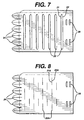
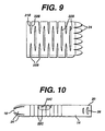
- the flex-enhancing elements are disposed along the length of the barrel 14. They may either be aligned along this length, or they may be arranged in a substantially offset, alternating pattern. When the flex-enhancing elements are aligned along the length, the applicator 10 will generally have flexibility primarily in one plane through its central axis. When they are offset (as shown in Figs. 8 and 9), the applicator will generally have flexibility in more than one plane.
- the flex-enhancing elements may result in the segmentation of the structural member into discrete units such as short lengths of tube which are substantially shorter than their diameter. These segments will then be held together and maintained as a flexible barrel 14 by the outer flexible material 28 and optionally by the inner flexible material 29.
- the flex-enhancing elements may also be the result of a continuous spiral slit which results in a plurality of slits when viewed in longitudinal cross-section. Again, this type of flex-enhancing elements would benefit from the use of at least the outer flexible material 28 to hold the structural material together as a barrel 14.
- the flex-enhancing elements are preferably arranged and configured to substantially maintain the longitudinal compressive strength of the structural member.
- the user is able to maintain control of the insertion device, especially the barrel 14, during its insertion into the body cavity.
- the flex enhancing elements in the barrel 14 are perforations which have edges 21, 23. These perforations may have a major axis and a minor axis. Preferably, the major axis of the flex-enhancing elements is oriented substantially perpendicular to the length of the applicator.
- the edges 21, 23 of the perforations may abut (for example, the slits 22A shown in Fig. 8) or they may be separated (for example, the slots 22 shown in Fig. 3 and the cut-outs 22B shown in Fig. 9) when the barrel 14 is in a relaxed, unstressed state.
- the flex-enhancing elements allow the barrel 14 to flex into a curved orientation as shown in Fig. 5.
- the edges 21A, 23A of slits 22A will separate, while the edges 21, 23 of slots 22 will generally close as shown in Fig, 6. While this discussion focuses on flex-enhancing elements in the barrel 14, it is also applicable to flex-enhancing elements (not shown) in the plunger 16.
- the barrel 14 may be made of structural materials generally known to those of ordinary skill in the art. These materials include, without limitation, plastic sheet; moldable plastic, such as injection-moldable or blow-moldable plastic; biodegradable plastic, such as those disclosed in the commonly assigned application, Dabi et al., U.S. Serial No. 08/006,013, filed January 15, 1993 (herein incorporated by reference); and cardboard.
- the cardboard used as structural materials can be a single layer of cardboard material, or it can be a plurality of laminated layers to provide multiple benefits relating to the various layers.
- Useful cardboard stock for the formation of the tubular elements include, without limitation, paperboard, cardboard, cup stock, paper, and the like.
- the structural material preferably has disposed thereon the flexible material 28 generally discussed above to provide aesthetics similar to conventional plastic-coated or plastic-laminated cardboard applicators.
- This flexible material 28 is preferably a substantially continuous layer which spans and is unsupported by the structural material at the flex-enhancing elements .
- the flexible material 28 may be a plastic film, an elastomeric film, coated paper, and the like.
- Useful plastics include, without limitation, polyolefins such as polyethylene and polypropylene, polyesters such as polyethylene terephthalate, polycaprolactone, polyvinyl alcohol, ethylene-vinyl acetate copolymers, cellophane, and the like.
- Useful elastomers include, without limitation, natural rubber, styrene-butadiene copolymers, isobutylene-isoprene copolymers, polychloroprene systems (Neoprene Registered TM, duPont), polyurethanes, polysulfide rubbers, polyacrylate elastomers comprising the copolymerization of ethyl acrylate and acrylic acid-lower alkanol esters, nitrile rubber, butyl rubber, polysulfide rubber, polyisoprene, ethylene-propylene terpolymers such as EDPM rubber, silicone rubber, and the like.
- Useful coated papers include waxed paper, plastic-coated paper, silicone-coated paper, and the like.
- Preferred structural materials include cardboards and laminated cardboards. These plastic laminated cardboard materials may include additional layers such as adhesive layers, tie layers, and the like.
- Typical dimensions for the barrel 14 useful in tampon applicators include a length of about 5 to 8 cm, a diameter of about 8 to 16 mm, and thicknesses of about 0.4 to 0.6 mm.
- the diameter of the plunger 16 is less than the diameter of the barrel 14 to allow for a telescopic arrangement of the plunger 16 within the barrel 14 as shown in Fig. 3.
- the insertion device can be formed in several ways currently known to those of ordinary skill in the art.
- Tubular structural members may be formed as a continuous spiral-wound tube and subsequently cut to form the tubular elements.
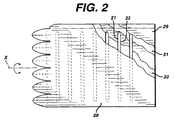
- individual tubular elements or shorter tubes can be formed from rectangular sheets (or blanks) of cardboard. These blanks can be rolled about a central axis X in the manner indicated in Fig. 2 and secured with longitudinal seams 32 as shown in Fig. 4. This is shown in greater detail in Hinzmann, U.S. Patent No. 4,755,164, herein incorporated by reference. Alternatively, they can be convolutely wound as disclosed in Whitehead, U.S. Patent No. 4,508,531.
- the shorter tubes can be cut to form a small number of tubular elements, similar to the continuous, spiral-wound tubes.
- the user simply removes the tampon applicator 10 from any protective wrappers in which it may be packaged, holds the gripper end 20 and inserts the insertion end 18 of the applicator into the vagina.
- the expulsion member 16 is pushed into the barrel 14 to expel the tampon 12 from the barrel 14, and into the vagina.
- the applicator 10 is then withdrawn from the vagina and may be discarded.
- compositions and/or medicaments may be in the form of solids, creams, foams, gels, and the like.
Claims (31)
- Applicateur souple (10) destiné à insérer un article, tel qu'un tampon menstruel (12), à l'intérieur d'une cavité d'un corps de mammifère comprenant :a) un élément structurel creux, allongé (14) approprié pour contenir l'article insérable (12), l'élément structurel (14) ayant des surfaces interne et externe opposées, une longueur qui est sensiblement supérieure à la fois à une largeur et à une hauteur, des extrémités d'insertion (18) et de prise (20) opposées et une pluralité d'éléments de renforcement de la souplesse (22, 22A, 22B, 22C) qui sont agencés et configurés de façon à augmenter la souplesse latérale de l'élément structurel (14), qui sont disposés le long de la longueur de l'élément structurel (14) ; etb) un élément d'expulsion allongé (16) qui peut coulisser à l'intérieur de l'élément structurel (14).
- Applicateur souple selon la revendication 1, dans lequel les éléments de renforcement de la souplesse (22, 22A, 22B, 22C) résultent en la segmentation de l'élément structurel (14) en des unités discrètes qui seront tenues ensemble et maintenues comme un cylindre souple (14) par le matériau souple externe (28).
- Applicateur souple selon la revendication 1, dans lequel les éléments de renforcement de la souplesse (22, 22A, 22B, 22C) sont le résultat d'une fente spirale continue qui résulte en une pluralité de fentes, vu suivant une coupe longitudinale.
- Applicateur souple selon la revendication 1, dans lequel les éléments de renforcement de la souplesse (22, 22A, 22B, 22C) sont agencés et configurés de façon à essentiellement maintenir la force de compression longitudinale de l'élément structurel (14).
- Applicateur souple selon la revendication 1, qui comprend en outre une couche d'un matériau souple (28) disposé sur la surface externe de l'élément structurel (14).
- Applicateur souple selon la revendication 5, dans lequel la couche de matériau souple (28) n'est pas supportée par l'élément structurel (14) dans la région des éléments de renforcement de la souplesse (22, 22A, 22B, 22C).
- Applicateur souple selon la revendication 5, dans lequel la couche de matériau souple (28) est une couche polymérique.
- Applicateur souple selon la revendication 7, dans lequel la couche polymérique est un film.
- Applicateur souple selon la revendication 5, dans lequel la couche de matériau souple (28) comprend un élastomère.
- Applicateur souple selon la revendication 1, dans lequel l'élément de renforcement de la souplesse (22A) comprend des perforations ayant des bords (21, 21A, 23, 23A).
- Applicateur souple selon l'une quelconque des revendications 1 ou 10, dans lequel les bords (21A, 23A) se rencontrent.
- Applicateur souple selon l'une quelconque des revendications 1 ou 10, dans lequel les bords (21, 23) sont espacés.
- Applicateur souple selon la revendication 1, dans lequel les éléments de renforcement de la souplesse (22, 22A, 22B, 22C) comprennent un pli (22C).
- Applicateur souple selon la revendication 13, dans lequel le pli (22C) est sensiblement dirigé vers l'intérieur moyennant quoi la surface externe de l'élément structurel (14) est sensiblement régulière.
- Applicateur souple selon la revendication 1, dans lequel l'extrémité d'insertion (18) est sensiblement fermée.
- Applicateur souple selon la revendication 1, dans lequel l'extrémité de prise (20) possède au moins une caractéristique de renforcement de prise (26).
- Applicateur souple selon la revendication 1, dans lequel les éléments de renforcement de la souplesse (22, 22A, 22B, 22C) ont un axe principal et un axe secondaire, l'axe principal est orienté sensiblement de manière perpendiculaire à la longueur de l'applicateur (10).
- Applicateur souple selon la revendication 1, dans lequel les éléments de renforcement de la souplesse (22, 22B, 22C) sont sensiblement alignés suivant la longueur de l'applicateur (10).
- Applicateur souple selon la revendication 1, dans lequel les éléments de renforcement de la souplesse (22A) sont agencés selon un modèle alternant sensiblement décalé suivant la longueur de l'applicateur (10).
- Applicateur souple selon la revendication 1, dans lequel l'élément d'expulsion élongé (16) comprend des éléments de renforcement de la souplesse.
- Applicateur souple selon la revendication 1, dans lequel l'élément structurel creux et élongé (14) comprend un tube sensiblement cylindrique.
- Applicateur souple selon la revendication 1, qui comprend en outre une couche d'un matériau souple (29) agencé sur la surface interne de l'élément structurel (14).
- Procédé de fabrication d'un applicateur souple (10) selon l'une quelconque des revendications précédentes comprenant les étapes consistant à :a) former les éléments de renforcement de la souplesse (22, 22A, 22B, 22C) dans l'élément structurel (14), l'élément structurel (14) ayant une surface externe ;b) superposer une couche d'un matériau souple (28) sur la surface externe de l'élément structurel (14) ; etc) former l'élément structurel (14) en un élément creux allongé approprié pour contenir l'élément insérable (12), l'élément creux ayant une longueur sensiblement supérieure à la fois à une largeur et à une hauteur, et des extrémités d'insertion (18) et de prise (20) opposées.
- Procédé selon la revendication 23, dans lequel l'étape consistant à superposer la couche de matériau souple (28) comprend (i) l'étape consistant à appliquer un matériau de stratification sur l'élément de surface externe et (ii) l'étape consistant à appliquer la couche de matériau souple (28) sur le matériau de stratification.
- Procédé selon la revendication 23, dans lequel l'étape consistant à former les éléments de renforcement de la souplesse (22, 22A, 22B) comprend l'étape consistant à perforer l'élément structurel (14).
- Procédé selon la revendication 25, dans lequel l'étape consistant à perforer l'élément structurel (22A, 22B) comprend l'étape consistant à créer des fentes dans l'élément structurel (14).
- Procédé selon la revendication 25, dans lequel l'étape consistant à former un élément creux allongé (14) comprend l'étape consistant à former un tube cylindrique.
- Procédé selon la revendication 27, dans lequel le tube est un tube enroulé de manière convolutée.
- Procédé selon la revendication 27, dans lequel le tube est un tube enroulé en spirale.
- Procédé selon la revendication 27, dans lequel le tube est un tube cousu de manière longitudinale.
- Procédé selon la revendication 23, qui comprend en outre l'étape consistant à sensiblement fermer l'extrémité d'insertion (18) de l'élément creux (14).
Applications Claiming Priority (3)
| Application Number | Priority Date | Filing Date | Title |
|---|---|---|---|
| US08/885,719 US6019743A (en) | 1997-06-30 | 1997-06-30 | Flexible applicator for inserting an article into a mammalin body cavity |
| US885719 | 1997-06-30 | ||
| PCT/US1998/012658 WO1999000097A1 (fr) | 1997-06-30 | 1998-06-17 | Applicateur souple pour insertion d'un article dans une cavite anatomique de mammifere |
Publications (2)
| Publication Number | Publication Date |
|---|---|
| EP0925051A1 EP0925051A1 (fr) | 1999-06-30 |
| EP0925051B1 true EP0925051B1 (fr) | 2003-08-27 |
Family
ID=25387557
Family Applications (1)
| Application Number | Title | Priority Date | Filing Date |
|---|---|---|---|
| EP98930348A Expired - Lifetime EP0925051B1 (fr) | 1997-06-30 | 1998-06-17 | Applicateur souple pour insertion vaginale ou rectale d'un article, comme un tampon |
Country Status (12)
| Country | Link |
|---|---|
| US (3) | US6019743A (fr) |
| EP (1) | EP0925051B1 (fr) |
| JP (1) | JP2001500046A (fr) |
| CN (1) | CN1229351A (fr) |
| AR (1) | AR015921A1 (fr) |
| AT (1) | ATE247941T1 (fr) |
| AU (1) | AU753096B2 (fr) |
| BR (1) | BR9806182A (fr) |
| CA (1) | CA2263974C (fr) |
| DE (1) | DE69817522T2 (fr) |
| WO (1) | WO1999000097A1 (fr) |
| ZA (1) | ZA985671B (fr) |
Families Citing this family (48)
| Publication number | Priority date | Publication date | Assignee | Title |
|---|---|---|---|---|
| US6019743A (en) | 1997-06-30 | 2000-02-01 | Mcneil-Ppc, Inc. | Flexible applicator for inserting an article into a mammalin body cavity |
| US6171426B1 (en) * | 1998-06-26 | 2001-01-09 | Mcneill-Ppc, Inc. | Method of making a coated tampon applicator |
| US6458064B1 (en) * | 1998-08-14 | 2002-10-01 | Kimberly-Clark Worldwide, Inc. | Coating Method |
| US6170137B1 (en) * | 1998-09-03 | 2001-01-09 | Mcintire Jerald R. | Embalming fluid distribution tube |
| IL126111A0 (en) * | 1998-09-07 | 1999-05-09 | Medivice Systems Ltd | Tampon applicator |
| US6936443B2 (en) * | 2000-04-03 | 2005-08-30 | Cytyc Corporation | Detection and typing of human papillomavirus using PNA probes |
| US6645136B1 (en) | 2000-09-28 | 2003-11-11 | Kimberly-Clark Worldwide, Inc. | Incontinence insert applicators and methods for their use |
| US7465295B2 (en) * | 2000-10-20 | 2008-12-16 | Bergeron Michel G | Applicator for the delivery of topical formulations into mucosal cavities |
| US6419641B1 (en) * | 2000-11-28 | 2002-07-16 | Promex, Llc | Flexible tip medical instrument |
| AU2002326065A1 (en) * | 2001-08-16 | 2003-03-03 | Peter James Brian Lamb | Applicator for introducing an object into a vagina |
| US6511452B1 (en) | 2001-09-21 | 2003-01-28 | Playtex Products, Inc. | Tampon applicator with improved fingergrip |
| US6695763B2 (en) | 2002-01-02 | 2004-02-24 | Kimberly-Clark Worldwide, Inc. | Incontinence insert device and method of using same |
| US7104968B2 (en) * | 2002-06-14 | 2006-09-12 | Mcneil-Ppc, Inc. | Applicator device for suppositories and the like |
| US7717873B2 (en) * | 2002-06-14 | 2010-05-18 | Mcneil-Ppc, Inc. | Applicator device for suppositories and the like |
| US7217252B2 (en) * | 2002-06-14 | 2007-05-15 | Mcneil-Ppc, Inc. | Applicator device for medicated materials |
| US7198612B2 (en) * | 2002-06-14 | 2007-04-03 | Mcneil-Ppc, Inc. | Applicator device for suppositories and the like |
| US20040010220A1 (en) * | 2002-06-21 | 2004-01-15 | Playtex Products, Inc. | Tampon applicator with improved fingergrip and method of making same |
| KR100829669B1 (ko) * | 2002-06-21 | 2008-05-16 | 플레이텍스 프로덕츠, 인크. | 테이퍼된 탐폰 어플리케이터 |
| US7727208B2 (en) | 2002-09-12 | 2010-06-01 | Playtex Products, Inc. | Ergonomic tampon applicator |
| US6770025B2 (en) | 2002-09-18 | 2004-08-03 | Kimberly-Clark Worldwide, Inc. | Molar shaped vaginal incontinence insert |
| US6676594B1 (en) | 2002-09-18 | 2004-01-13 | Kimberly-Clark Worldwide, Inc. | C-shaped vaginal incontinence insert |
| US6939289B2 (en) * | 2002-10-21 | 2005-09-06 | Kimberly-Clark Worldwide, Inc. | Ellipitcal applicator system |
| US20040078013A1 (en) * | 2002-10-21 | 2004-04-22 | Kimberly-Clark Worldwide, Inc. | Lubricated incontinence device applicator |
| US6808485B2 (en) | 2002-12-23 | 2004-10-26 | Kimberly-Clark Worldwide, Inc. | Compressible resilient incontinence insert |
| US9192522B2 (en) | 2003-05-02 | 2015-11-24 | Eveready Battery Company, Inc. | Tampon assembly having shaped pledget |
| US7887525B2 (en) * | 2003-06-26 | 2011-02-15 | Playtex Products, Inc. | Coating composition with color and/or optical components and a tampon applicator coated therewith |
| AU2005220860B2 (en) | 2004-03-08 | 2011-03-03 | Playtex Products, Inc. | Tampon applicator and method for making same |
| US20070027425A1 (en) * | 2005-07-27 | 2007-02-01 | The Procter & Gamble Company | Collapsible tampon applicator |
| US7815594B2 (en) | 2006-06-12 | 2010-10-19 | Playtex Products, Inc. | Tampon assembly providing proper bodily placement of a pledget |
| US20080097286A1 (en) * | 2006-08-04 | 2008-04-24 | 0696578 B.C. Ltd Incorporation | Anal ointment applicator |
| US20080088063A1 (en) * | 2006-10-13 | 2008-04-17 | Heritage Stone Llc | Casting system and method for producing a veneer product |
| US8075512B2 (en) | 2007-04-13 | 2011-12-13 | The Procter & Gamble Company | Applicator having an enhanced gripping region |
| US8597267B2 (en) * | 2007-04-18 | 2013-12-03 | The Procter & Gamble Company | Tampon having at least one physical discontinuity |
| US8128592B2 (en) * | 2007-07-11 | 2012-03-06 | Apollo Endosurgery, Inc. | Methods and systems for performing submucosal medical procedures |
| EP2340795B1 (fr) * | 2008-08-29 | 2018-03-07 | Unicharm Corporation | Applicateur de tampons |
| US20110190686A1 (en) * | 2010-01-29 | 2011-08-04 | Margaret Henderson Hasse | Applicator for feminine hygiene devices |
| US20110190687A1 (en) * | 2010-01-29 | 2011-08-04 | Nancy Deters Slayton | Applicator having improved surface elements |
| CN103585711B (zh) * | 2013-10-31 | 2016-09-14 | 吴江纽风环境科技有限公司 | 一种给药器 |
| CA3009666A1 (fr) | 2015-12-29 | 2017-07-06 | CEEK Enterprises | Manchon pour speculum et son utilisation |
| CA3209391A1 (en) | 2015-12-29 | 2017-07-06 | Ceek Women's Health, Inc. | Speculum with secondary bills |
| EP3397135A2 (fr) | 2015-12-29 | 2018-11-07 | Ceek Enterprises | Manchon pouvant être introduit pour spéculum et son utilisation |
| CN109069169B (zh) * | 2016-05-06 | 2021-07-20 | 波士顿科学医学有限公司 | 医疗系统、装置和相关方法 |
| US10456016B2 (en) | 2017-05-05 | 2019-10-29 | CEEK Enterprises | Applicator for a speculum accessory sleeve and use thereof |
| EP3691589B1 (fr) | 2017-10-06 | 2021-12-22 | Essity Hygiene and Health Aktiebolag | Applicateur de tampon |
| RU2734200C1 (ru) | 2017-10-06 | 2020-10-13 | Эссити Хайджин Энд Хелт Актиеболаг | Аппликатор тампона |
| WO2019068349A1 (fr) | 2017-10-06 | 2019-04-11 | Essity Hygiene And Health Aktiebolag | Applicateur pour tampon |
| US11529264B2 (en) | 2017-10-06 | 2022-12-20 | Essity Hygiene And Health Aktiebolag | Tampon applicator |
| USD986415S1 (en) | 2020-09-11 | 2023-05-16 | Ceek Women's Health, Inc. | Speculum |
Family Cites Families (16)
| Publication number | Priority date | Publication date | Assignee | Title |
|---|---|---|---|---|
| US3696812A (en) | 1970-08-13 | 1972-10-10 | Tampax Inc | Tampon applicator |
| US4318404A (en) * | 1979-05-29 | 1982-03-09 | Cunningham Thomas W | Applicator and tampon |
| US4508531A (en) * | 1982-12-06 | 1985-04-02 | Kimberly-Clark Corporation | Convolutely wound paper tampon tube |
| US5267953A (en) * | 1986-04-23 | 1993-12-07 | Kimberly-Clark Corporation | Curved tampon applicator and a process for forming the applicator and for assembling an absorbent tampon into said applicator |
| JP2561922B2 (ja) * | 1986-04-23 | 1996-12-11 | キンバリ− クラ−ク コ−ポレ−シヨン | タンポン・アプリケ−タ |
| US4755164A (en) * | 1986-12-23 | 1988-07-05 | Hauni Richmond, Inc. | Method of and apparatus for making applicators of pledgets and the like |
| US4822332A (en) * | 1988-03-31 | 1989-04-18 | Tambrands Inc. | Device for delivering an object to a cavity |
| US5910520A (en) | 1993-01-15 | 1999-06-08 | Mcneil-Ppc, Inc. | Melt processable biodegradable compositions and articles made therefrom |
| EP0613672A1 (fr) * | 1993-03-01 | 1994-09-07 | Tambrands, Inc. | Applicateur de tampon soluble dans l'eau |
| US5395308A (en) * | 1993-09-24 | 1995-03-07 | Kimberly-Clark Corporation | Thermoplastic applicator exhibiting accelerated breakup when immersed in water |
| US5409469A (en) * | 1993-11-04 | 1995-04-25 | Medtronic, Inc. | Introducer system having kink resistant splittable sheath |
| US5437628A (en) * | 1993-11-10 | 1995-08-01 | Kimberly-Clark Corporation | Curved tampon applicator having an improved fingergrip |
| US5986000A (en) * | 1995-05-22 | 1999-11-16 | Playtex Products, Inc. | Soft, flexible composition and method for making same |
| US5709652A (en) * | 1995-06-28 | 1998-01-20 | Mcneil-Ppc, Inc. | Tampon applicator tube having apertured finger grip |
| US6019743A (en) | 1997-06-30 | 2000-02-01 | Mcneil-Ppc, Inc. | Flexible applicator for inserting an article into a mammalin body cavity |
| JP4027503B2 (ja) | 1998-06-26 | 2007-12-26 | 本田技研工業株式会社 | 船外機 |
-
1997
- 1997-06-30 US US08/885,719 patent/US6019743A/en not_active Expired - Fee Related
-
1998
- 1998-06-17 AU AU79758/98A patent/AU753096B2/en not_active Ceased
- 1998-06-17 BR BR9806182-8A patent/BR9806182A/pt not_active IP Right Cessation
- 1998-06-17 CA CA002263974A patent/CA2263974C/fr not_active Expired - Fee Related
- 1998-06-17 EP EP98930348A patent/EP0925051B1/fr not_active Expired - Lifetime
- 1998-06-17 CN CN98800869A patent/CN1229351A/zh active Pending
- 1998-06-17 JP JP11505600A patent/JP2001500046A/ja not_active Ceased
- 1998-06-17 WO PCT/US1998/012658 patent/WO1999000097A1/fr active IP Right Grant
- 1998-06-17 AT AT98930348T patent/ATE247941T1/de not_active IP Right Cessation
- 1998-06-17 DE DE69817522T patent/DE69817522T2/de not_active Expired - Fee Related
- 1998-06-29 AR ARP980103150A patent/AR015921A1/es active IP Right Grant
- 1998-06-29 ZA ZA9805671A patent/ZA985671B/xx unknown
-
1999
- 1999-03-26 US US09/277,644 patent/US6500140B1/en not_active Expired - Fee Related
- 1999-03-26 US US09/277,648 patent/US6196988B1/en not_active Expired - Fee Related
Also Published As
| Publication number | Publication date |
|---|---|
| AR015921A1 (es) | 2001-05-30 |
| EP0925051A1 (fr) | 1999-06-30 |
| DE69817522T2 (de) | 2004-06-24 |
| US6500140B1 (en) | 2002-12-31 |
| CA2263974C (fr) | 2007-09-11 |
| US6019743A (en) | 2000-02-01 |
| CA2263974A1 (fr) | 1999-01-07 |
| BR9806182A (pt) | 1999-11-16 |
| ATE247941T1 (de) | 2003-09-15 |
| WO1999000097A1 (fr) | 1999-01-07 |
| ZA985671B (en) | 2000-05-09 |
| AU753096B2 (en) | 2002-10-10 |
| US6196988B1 (en) | 2001-03-06 |
| JP2001500046A (ja) | 2001-01-09 |
| AU7975898A (en) | 1999-01-19 |
| CN1229351A (zh) | 1999-09-22 |
| DE69817522D1 (de) | 2003-10-02 |
Similar Documents
| Publication | Publication Date | Title |
|---|---|---|
| EP0925051B1 (fr) | Applicateur souple pour insertion vaginale ou rectale d'un article, comme un tampon | |
| EP1198215B1 (fr) | Applicateur de tampon possedant des caracteristiques de prehension ameliorees | |
| US4508531A (en) | Convolutely wound paper tampon tube | |
| EP0918501B1 (fr) | Tube applicateur pour tampon pourvu d'une zone de prehension a fentes pour les doigts | |
| US5348534A (en) | Tampon applicator | |
| EP1301157B1 (fr) | Applicateur d'article menstruel comportant un element de prehension | |
| ZA200200678B (en) | A method of making applicators having improved finger grip features. | |
| US6171426B1 (en) | Method of making a coated tampon applicator | |
| US5643196A (en) | Tampon applicator | |
| US20070021708A1 (en) | Tampon applicator having a multi-directional rim | |
| US5683358A (en) | Applicator for holding and dispensing a substance | |
| EP0723768A2 (fr) | Applicateur de tampon | |
| US6322531B1 (en) | Insertable applicator having a pivotal finger grip tab | |
| MXPA99002017A (en) | Flexible applicator for inserting an article into a mammalian body cavity | |
| US20070021710A1 (en) | Tampon applicator having a multi-directional rim | |
| EP0581136A1 (fr) | Manchon pour applicateur de tampons | |
| AU2005201314A1 (en) | Tampon applicator having improved gripping features | |
| US20070021709A1 (en) | Tampon applicator having a multi-directional rim | |
| MXPA98000211A (en) | Tampon applicator tub that has brake with openings for those of |
Legal Events
| Date | Code | Title | Description |
|---|---|---|---|
| PUAI | Public reference made under article 153(3) epc to a published international application that has entered the european phase |
Free format text: ORIGINAL CODE: 0009012 |
|
| 17P | Request for examination filed |
Effective date: 19990226 |
|
| AK | Designated contracting states |
Kind code of ref document: A1 Designated state(s): AT DE FR IT NL |
|
| 17Q | First examination report despatched |
Effective date: 20010207 |
|
| GRAH | Despatch of communication of intention to grant a patent |
Free format text: ORIGINAL CODE: EPIDOS IGRA |
|
| RTI1 | Title (correction) |
Free format text: FLEXIBLE APPLICATOR FOR VAGINALLY OR RECTALLY INSERTING AN ARTICLE, LIKE A CATAMENIAL TAMPON |
|
| RTI1 | Title (correction) |
Free format text: FLEXIBLE APPLICATOR FOR VAGINALLY OR RECTALLY INSERTING AN ARTICLE, LIKE A CATAMENIAL TAMPON |
|
| GRAH | Despatch of communication of intention to grant a patent |
Free format text: ORIGINAL CODE: EPIDOS IGRA |
|
| GRAA | (expected) grant |
Free format text: ORIGINAL CODE: 0009210 |
|
| AK | Designated contracting states |
Designated state(s): AT DE FR IT NL |
|
| REF | Corresponds to: |
Ref document number: 69817522 Country of ref document: DE Date of ref document: 20031002 Kind code of ref document: P |
|
| ET | Fr: translation filed | ||
| PLBE | No opposition filed within time limit |
Free format text: ORIGINAL CODE: 0009261 |
|
| STAA | Information on the status of an ep patent application or granted ep patent |
Free format text: STATUS: NO OPPOSITION FILED WITHIN TIME LIMIT |
|
| 26N | No opposition filed |
Effective date: 20040528 |
|
| PGFP | Annual fee paid to national office [announced via postgrant information from national office to epo] |
Ref country code: NL Payment date: 20060604 Year of fee payment: 9 |
|
| PGFP | Annual fee paid to national office [announced via postgrant information from national office to epo] |
Ref country code: AT Payment date: 20060613 Year of fee payment: 9 |
|
| PGFP | Annual fee paid to national office [announced via postgrant information from national office to epo] |
Ref country code: IT Payment date: 20060630 Year of fee payment: 9 |
|
| PGFP | Annual fee paid to national office [announced via postgrant information from national office to epo] |
Ref country code: DE Payment date: 20070614 Year of fee payment: 10 |
|
| PG25 | Lapsed in a contracting state [announced via postgrant information from national office to epo] |
Ref country code: AT Free format text: LAPSE BECAUSE OF NON-PAYMENT OF DUE FEES Effective date: 20070617 |
|
| NLV4 | Nl: lapsed or anulled due to non-payment of the annual fee |
Effective date: 20080101 |
|
| PG25 | Lapsed in a contracting state [announced via postgrant information from national office to epo] |
Ref country code: NL Free format text: LAPSE BECAUSE OF NON-PAYMENT OF DUE FEES Effective date: 20080101 |
|
| PGFP | Annual fee paid to national office [announced via postgrant information from national office to epo] |
Ref country code: FR Payment date: 20070608 Year of fee payment: 10 |
|
| REG | Reference to a national code |
Ref country code: FR Ref legal event code: ST Effective date: 20090228 |
|
| PG25 | Lapsed in a contracting state [announced via postgrant information from national office to epo] |
Ref country code: DE Free format text: LAPSE BECAUSE OF NON-PAYMENT OF DUE FEES Effective date: 20090101 |
|
| PG25 | Lapsed in a contracting state [announced via postgrant information from national office to epo] |
Ref country code: FR Free format text: LAPSE BECAUSE OF NON-PAYMENT OF DUE FEES Effective date: 20080630 |
|
| PG25 | Lapsed in a contracting state [announced via postgrant information from national office to epo] |
Ref country code: IT Free format text: LAPSE BECAUSE OF NON-PAYMENT OF DUE FEES Effective date: 20070617 |