EP0924698A2 - Automatic disc changer for a disc reproducing system - Google Patents
Automatic disc changer for a disc reproducing system Download PDFInfo
- Publication number
- EP0924698A2 EP0924698A2 EP99101213A EP99101213A EP0924698A2 EP 0924698 A2 EP0924698 A2 EP 0924698A2 EP 99101213 A EP99101213 A EP 99101213A EP 99101213 A EP99101213 A EP 99101213A EP 0924698 A2 EP0924698 A2 EP 0924698A2
- Authority
- EP
- European Patent Office
- Prior art keywords
- disc
- holder
- reproducing device
- space
- engaged
- Prior art date
- Legal status (The legal status is an assumption and is not a legal conclusion. Google has not performed a legal analysis and makes no representation as to the accuracy of the status listed.)
- Withdrawn
Links
Images


Classifications
-
- G—PHYSICS
- G11—INFORMATION STORAGE
- G11B—INFORMATION STORAGE BASED ON RELATIVE MOVEMENT BETWEEN RECORD CARRIER AND TRANSDUCER
- G11B17/00—Guiding record carriers not specifically of filamentary or web form, or of supports therefor
- G11B17/22—Guiding record carriers not specifically of filamentary or web form, or of supports therefor from random access magazine of disc records
- G11B17/30—Guiding record carriers not specifically of filamentary or web form, or of supports therefor from random access magazine of disc records wherein the playing unit is moved according to the location of the selected record
-
- G—PHYSICS
- G11—INFORMATION STORAGE
- G11B—INFORMATION STORAGE BASED ON RELATIVE MOVEMENT BETWEEN RECORD CARRIER AND TRANSDUCER
- G11B17/00—Guiding record carriers not specifically of filamentary or web form, or of supports therefor
- G11B17/22—Guiding record carriers not specifically of filamentary or web form, or of supports therefor from random access magazine of disc records
- G11B17/28—Guiding record carriers not specifically of filamentary or web form, or of supports therefor from random access magazine of disc records the magazine having a cylindrical shape with horizontal axis
Definitions
- the present invention relates to a disc reproducing for reproducing information recorded on a disc such as a CD, and more particularly to an automatic disc changer system in the reproducing system.
- Japanese Patent Application Laid-open 60-138769 discloses an automatic disc changer system, whereby it is possible to store a large number of discs in a small space in the system, to change a disc at a high speed, and to meet requests for a simple structure with an accurate operation.
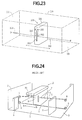
- Fig. 24 shows the system.
- the system comprises a casing 1 having a pair of tray holders 2 secured thereto.
- a disc tray (not shown) on which a plurality of CDs are mounted in the vertical disposition is detachably mounted between the holders 2.
- a pair of pulleys 4 are rotatably mounted on opposite side plates 3 of the casing 1.
- a wire 5 is provided between the pulleys 4 for preventing the discs stored in the tray from removing from the tray.
- An end 6 of the wire 5 is secured to a side of a disc reproducing device 10 through a spring 7.
- the other end 8 of the wire is secured to an opposite side of the reproducing device 10.
- the reproducing device 10 is movable in the directions A and B along the discs between the side plates 3.
- the device 10 has a disc loading device 20 provided on a front portion thereof so as to pick up a selected disc from the tray and load the disc in the device 10 through an opening 11.
- the reproducing device 10 In an automatic changing operation of the disc, when one of the discs is selected to be reproduced, the reproducing device 10 is horizontally moved in the direction A or B and stopped at the position of the selected disc. In this state, the wire 5 is circulated together with the reproducing device 10 so that the wire does not obstruct the movement of the device. By the spring 7 on the wire, a predetermined tension is exerted on the device 10.
- the selected disc is loaded by the loading device 20 in the reproducing device 10 through the inlet 11.
- the wire 5 is secured to the device 10 and extended over the disc tray so that the disc which is accidentally removed from the tray caused by vibration is prevented from removing.
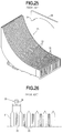
- Fig. 25 shows a disc tray 30 having a plurality of curved holding plates 31 so as to form spaces 32 there-between for storing the discs.
- the holding plate 31 has a tapered upper end.
- a disc 35 is stored in the space 32.
- a loading arm 33 rotatably mounted in the loading device 20 is inserted into the space 32 between the holding plates 31.
- a loading end 34 of the loading arm 33 is engaged with the disc 35 so that the disc is removed from the tray by returning the loading arm 33.
- the end 34 If the end 34 is deflected, the end may be inserted into an adjacent space 32 of the selected disc, causing troubles of the operation.
- An object of the present invention is to provide an automatic disc changer system in which dimension of parts is easily managed and a selected disc is accurately loaded.
- an automatic disc changer for a disc reproducing system having a casing for the automatic disc changer, and a plurality of disc holders arranged in the casing, comprising the disc holder having a plurality of holding plates forming spaces therebetween for storing a plurality of discs in vertical position, a reproducing device provided in the casing to be moved along the disc holders, the reproducing device having a loading arm to be inserted into the space for loading the disc on the reproducing device, a movable frame provided on the disc holder to be shifted by a pitch of the space in a direction of the arrangement of the disc holders, a plurality of guide projections provided on the movable frame, disposed adjacent to ends of the holding plates.
- the guide projections are arranged by a pitch which is twice as much as the pitch of the space, each of the guide projections having a triangular section the bottom of which has an approximately equal to a width of the space so as to close a corresponding space.
- Shifting means is provided for shifting the movable frame by one pitch of the space.
- each of the holding plates has a triangular tip end, and both edges of the bottom of the guide projection is disposed adjacent to tip ends of triangular tip ends of a pair of holding plates.
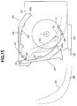
- a disc reproducing system having an automatic disc changer system comprises a casing 100, and a door 110 provided in front of the casing 100.
- a disc reproducing device 200 having a disc loading mechanism, a plurality of disc holders 300, and an auxiliary disc holder 400 are provided.
- the reproducing device 200 is movably mounted in the casing along the holders 300 disposed in the horizontal direction.
- the auxiliary disc holder 400 has a plus-one mechanism and is provided adjacent to the end holder 300.
- the door 110 has a transparent window 111 made of plastic, and a vertical inlet 112 formed corresponding to the auxiliary disc holder 400.
- the disc reproducing system of the present invention has two disc reproducing devices 200 slidably mounted on rails 102 and 104.
- Each of the disc reproducing devices 200 has a casing 201, a vertical opening 202 formed in a front portion of the casing 201, and four rollers 203 rotatably mounted around the inlet 202.
- a driving device (not shown) is provided in the reproducing device 200 for driving the reproducing device 200 along the rails 102 and 104.
- a wire 210 is provided between opposite side plates 101 of the casing 100 for preventing a disc stored in the disc holder 300 from removing from the holder.
- An end 211 of the wire 210 is connected to the side plate 101 of the casing and the other end 212 of the wire is connected to the other side plate 101 through a spring 213.
- the wire 210 is engaged with the four rollers 203 of each disc reproducing device 200 in the shape of an inverted U-shape so as to avoid the opening 202.
- the reproducing devices 200 can be independently moved along the wire 210 and the rails 102 and 104.
- the reproducing device 200 has a disc loading arm 220 rotatably mounted in the casing 201 and projected from the opening 202 to the disc holder 300.
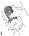
- FIG. 4 showing the disc holders 300 in the casing 100, four disc holders 300 are horizontally arranged corresponding to the front portions of the reproducing device 200.
- a plurality of optical discs 310 are stored in each holder 300 arranged in the horizontal direction.
- Each of the discs 310 is held in the holder in a vertical disposition so as to be removed from the holder.
- Each of the disc holders 300 comprises a base plate 308 having approximately an L-shape in section to be pivotally mounted on a supporting plate 120 provided in the casing 100, and a pair of side plates 301 having a curved periphery.
- a plurality of holding plates 303 are vertically secured to the base plate 308 between the side plates 301 at a predetermined distance so as to form a space 304 between a pair of holding plates 303 for holding the disc 310.
- Each of the holding plates 303 has the same configuration as the side plate 301 in plane, and an upper end portion has a triangular tip end 303a (Fig. 6).
- the disc holder 300 further has a front panel 315 secured to a front end of the base plate 308 to be downwardly projected.
- a plurality of guide perforations 305 are formed, arranged in the horizontal direction corresponding to the spaces 304.
- an encoder 307 having a plurality of detecting perforations 306 is provided corresponding to the perforations 305.
- a slide plate 320 and a movable frame 330 are attached.
- the slide plate 320 has an elongated opening 321, projecting portion 323 having a pin 324, and a plurality of blocking lugs 322 formed corresponding to the perforations 305 of the front panel 315 at every other perforations.
- a pair of side notches 325 are formed on opposite sides of the slide plate.
- the movable frame 330 comprises a guide plate 331 formed on a lower portion, a plurality of horizontally arrange guide projections 336 formed on an upper end portion, and a middle plate 337 provided between the guide plate 331 and the projections 336.
- the guide plate 331 has a cam slit 332 having cam portions 333 and 334 to be engaged with the pin 324 of the slide plate 320, and a pair of guide pins 335 provided on opposite sides.
- the cam portions 333 and 334 are deflected by the pitch of the space 304.
- Each guide projection 336 is in the form of a triangular prism.
- a bottom side of the triangular prism of the guide projection 336 has a length of one pitch of the space 304 between the holding plates 303 and both edges 336a corresponds to the tip ends 303a of the adjacent holding plates 303.
- the distance between the apexes 336a of the projections 336 is twice as much as the pitch of tip ends 303a.
- the base plate 308 has a pair of connecting lugs 302 rotatably engaged with the supporting plate 120 through connecting pins 302a (Fig. 5a), a pair of engaging projections 340 provided on opposite sides corresponding to the side notches 325 of the slide plate 320, and a pair of guide grooves 343 engaged with the guide pins 335 (Fig. 5b) of the guide plate 331 of the movable frame 330.
- a hook 342 is provided on the central portion for a spring 341.
- An engaging projection 345 is provided to be engaged with the opening 321 of the slide plate 320.
- the side notches 325 of the slide plate 320 are engaged with the corresponding projections 340, while the engaging projection 345 is engaged with the opening 321.
- the spring 341 is provide between a hook formed on the periphery of the opening 321 of the slide plate 320 and the hook 342 of the base plate 308 to urge the slide plate 320 to the front panel 315.
- the lugs 322 of the slide plate 320 are abutted on the periphery of the perforations 305 on the front panel at every other perforations.
- the guide plate 331 of the movable frame 330 is mounted on the projecting portion 323 of the slide plate 320 and the cam slit 322 is engaged with the pin 324, while the guide pins 335 (Fig. 5b) are slidably engaged with the guide grooves 343 of the base plate 308.
- the middle plate 337 is mounted between the connecting lugs 302, and the projections 336 are mounted on the upper ends of the holding plates 303.
- a cover plate 350 is mounted on the movable frame 330 and secured to the base plate 308 at the upper portions thereof.
- the movable frame 330 is movably held on the base plate 308 with the cover plate 350.
- the disc holder 300 can be rotated about the connecting pins 302a to be exposed from the casing.
- the disc 310 in the holder 300 can be easily taking out from the casing to be changed.
- the disc loading arm 220 is rotatably mounted on a shaft 221 secured to an inner frame 230.
- a disc discharging arm 223 is rotatably mounted on a shaft 222 secured to the inner frame 230.
- the loading arm 220 has a loading end 220a and a guide grooves 224 to be engaged with the periphery of the disc 310.
- the discharging arm 223 has a discharging end 223a and a guide groove 225 to be engaged with the periphery of the disc 310.
- the loading arm 220 and the discharging end 223a of the discharging arm 223 are adapted to pass through the inlet 202.
- Each of the guide grooves has a width slightly larger than the thickness of the disc 310.
- a slider 234 having a push rod 233 is slidably mounted on a lower portion of the inner frame 230.
- the slider 234 is moved in the direction shown by an arrow and the push rod 233 is engaged with a corresponding perforation 305 of the selected disc in the disc holder 300.
- the slider 234 is moved in the reverse direction so that the push rod 233 is retracted from the perforation.
- a position adjusting member 226 is rotatably mounted on an opposite surface of the inner frame 230 and urged in the direction a by a spring (not shown).
- the position adjusting member 226 has a pair of projections 227 and 228 provided on upper and lower ends thereof to be projected from elliptic holes 231 and 232 formed in the inner frame 230.
- two sizes of the discs can be loaded by the loading mechanism, for example the disc 310 having the diameter of 12 cm and a disc 311 having the diameter of 8 cm.
- one of the disc reproducing devices 200 is moved along the wire 210 to the selected disc in the holder 300.
- the rollers 203 provided on the reproducing device 200 are rotated on the wire 210 which is not circulated, so that the only selected device can be freely moved. Since the wire 210 is horizontally expanded along the disc holders 300, the discs 310 mounted in the holders are prevented from removing.
- the disc is selected in accordance with an address.
- a position sensor is mounted in the device 200 for detecting an on/off signal by the detecting perforation 306 of the encoder 307. Thus, the position of the selected disc is detected by the device 200.
- the slider 234 in the device 200 is moved to the left of Fig. 9 so that the push rod 233 is inserted into the perforation 305 corresponding to the selected disc.
- the blocking lugs 322 of the slide plate 320 close every other perforations 305. Namely, there are no lugs on the perforations 305 corresponding to the spaces 304 storing the discs of the even numbers. On the other hand, the lugs close the perforations 305 corresponding to the discs of the odd numbers.
- the push rod 233 is abutted on the lug 322 through the perforation 305 at the odd number, the lug is pushed so that the slide plate 320 is slid against the spring 341.
- the pin 324 of the slide plate 320 engaged with the cam slit 332 is slid to be engaged with the cam portion 333 so that the movable frame 330 is moved to the right in Fig. 5b.
- the guide projections 336 are moved by the one pitch of the space 304 to open the spaces 304 where the discs of the odd numbers are stored.
- the loading end 220a of the loading arm 220 is inserted into a space between the projections 336 and into the space 304 between holding plate 303.
- the width of the entrance gap that is, the distance between the apexes 336a of the guide projections 336 is twice as much as the pitch of the space 304. Therefore, the arm 220 easily enters the gap between the apexes and engages with the disc. Even if the arm 220 deflects from the center, the end 220a of the arm abuts on one of the slants 336b of the guide projection 336 so that the arm 220 is guided by the slant to the space 304. Thus, the arm can be exactly inserted into the space (Fig. 6).
- the loading arm 220 is inserted into the space 304 for the disc of the even number without engaging with the lug 322 and hence without shifting the projections 336.
- the loading arm 220 is rotated in the counterclockwise direction.
- the loading end 220a is inserted into the space between the projections 336 and into the space 304.
- the guide groove 224 is engaged with the disc 310.
- the arm 220 is further rotated so that the disc is removed from the space 304 of the holder 300 and inserted into the inlet 210 of the device 200.
- the disc is engaged with the end 223a of the discharging arm 223 in the device 200 and the guide groove 225 as shown in Fig. 11.
- Both of the arms 220 and 223 are further rotated in the counterclockwise direction.
- a periphery of the disc 310 is engaged with the projection 227 of the position adjusting member 226 so that the projection 227 is rotated in the direction b and engaged with the hole 231.
- the projection 228 engages with the hole 232, accordingly.
- the disc is loaded to the clamping position P.
- the disc is clamped to a turntable (not shown) by a clamper (not shown). In this state, since the end 220a of the loading arm 220 is disengaged from the disc 310. The disc is reproduced without disturbed by the arm.
- the disc 310 is clamped to the position P and the discharging arm 223 is rotated in the clockwise direction to engage the end 223a with the disc.
- the disc is pushed to be disengaged from the projections 228 and 227.
- the adjusting member 226 is rotated in the direction a by the spring to be returned to the position.
- the guide grooves 224 and 225 of the arms engage with the periphery of disc and guide the disc to be discharged from the inlet 202.
- the disc is stored in the holder.
- the slider 234 is moved to disengage the rod 233 from the perforation 305.
- the operation is approximately the same as the disc 310. Namely, the arm 220 is rotated to engage the disc 311 in the space 304 at the end 220a so as to remove the disc 311 from the space.
- the disc 311 is loaded in the device 200 through the inlet 202 by the end 220a and engaged with the end 223a of the arm 223 as shown in Fig. 14.
- the disc 311 is guided to the clamping position P by the ends 220a and 223a. Since the disc 311 is smaller than the disc 310, the disc 311 is not engaged with the projection 227 of the adjusting member 226.
- the disc 311 is engaged with the projection 228 which is not rotated and held in the position P by the end 220a of the arm 220 and the projection 228 as shown in Fig. 15.
- the disc 311 When discharging the disc 311, the disc 311 is guided by the ends 233a and 220a to be discharged from the inlet 202.
- the holder comprises a left frame member 420 and a right frame member 440.
- a vertical inlet 410 is formed between the left and right frame members corresponding to the inlet 112 of the door 110.
- a vertical space 401 is formed between the frame members. The loading arm 220 of the reproducing device 200 can be inserted into the space 401.
- the left frame member 420 has a supporting member 424 pivotally mounted on a shaft 423.
- the supporting member 424 is urged to the space 401.
- the supporting member 424 has a pair of rollers 422a and 422b rotatably mounted thereon.
- the roller 422a (422b) is mounted in the inclined disposition.
- An upper end of the shaft 423 is rotatably engaged with a support 435.
- a lower end of the shaft is secured to a gear 425 having a pulley 425a coaxial with the gear 425.
- a belt 427 is provided between the pulley 425a and a drive shaft 426a of a motor 426.
- the motor 426 is operated for loading the disc in the holder 400 when the disc is inserted into the inlet 410.
- the gear 425 engages with a gear 428 which engages with a gear (not shown) for rotating rollers 422a and 422b.
- the supporting member 242 further has a cam member 433 provided on a lower portion thereof.
- the left frame member 420 has a hole 420a corresponding to the reproducing device 200 to be engaged with the push rod 233 of the slider 234.
- a slider 430 is provide on the lower portion to be slidable in the direction shown by an arrow.
- the slider 430 has a pair of slits 431 and tapered end 430a engaged with the cam member 433 of the supporting member 424. In the slit 431, a pin 432 secured to the left frame member is engaged.
- a lock member 421 is rotatably mounted on a shaft 436 secured to the left member 420 at the inlet 410 for preventing the disc from inserting into the inlet 410.
- the lock member 421 has a lower engaging portion 437 engaged with a lower end of the supporting member 424 and an upper lock portion 438 (Fig. 17) to be projected on the inlet 410.
- felts 439a, 439b and 439c are provided on the left frame member 420.
- Fig. 22 shows the right frame member 440.
- the right member 440 has a grooves 441 and 442 formed corresponding to the rollers 422a and 422b of the left member 420, and felts 443a, 443b and 443c.
- An engaging groove 444 is provided to be engaged with the lock portion 438 of the lock member 421.
- a sensor (not shown) in the holder 400 detects it to drive the motor 426.
- the motor 426 rotates the drive shaft 426a to rotate the gear 425 through the belt 427 and the pulley 425a.
- the gear 428 is rotated to rotate the rollers 422a and 422b.
- the disc 310 is loaded in the holder 400 and the lower portion of the disc is abutted on the rollers 422a, 422b which are inclined on the supporting member 424.
- the motor 426 stops.
- the disc is engaged with the rollers 422a and 422b and the felts 439a to 439c and 443a to 443c to be stably held in the holder.
- length of the roller is determined to a half of the length of the inlet 410.
- the reproducing device 200 is moved to the holder 400 and the push rod 233 of the slider 234 is inserted into the hole 420a to push the slider 430 to the right of Fig. 19.
- the tapered end 430a is engaged with the cam member 433 of the supporting member 424 to urge the supporting member 424 away from the space 401.
- the rollers 422a and 422b are disengaged from the disc.
- the supporting member 424 is moved, the lower end thereof is abutted on the engaging portion 437 to rotate the lock member 421 in the clockwise direction of Fig. 17.
- the upper lock portion 438 is projected on the inlet 410.
- the disc is loaded in the reproducing device 200 by the arms 220 and 223 in the same manner as hereinbefore described.
- Fig. 23 shows a modification in which a single disc reproducing device 200 is provided. As a further modification, three or more reproducing devices can be provided.
- a pin can be used.
- the projections 336 of the triangular prism in the movable frame 330 can be replaced in the other shape, such as a semi-cylindrical shape.
- the width of the entrance gap for the loading arm is twice as much as the pitch of the space storing the disc, the loading arm is exactly inserted into the space through the gap, guided by the guide projections.
- the reproduction of a desired disc is ensured.
Landscapes
- Automatic Disk Changers (AREA)
Abstract
Description
- The present invention relates to a disc reproducing for reproducing information recorded on a disc such as a CD, and more particularly to an automatic disc changer system in the reproducing system.
- Japanese Patent Application Laid-open 60-138769 discloses an automatic disc changer system, whereby it is possible to store a large number of discs in a small space in the system, to change a disc at a high speed, and to meet requests for a simple structure with an accurate operation.
- Fig. 24 shows the system. The system comprises a
casing 1 having a pair oftray holders 2 secured thereto. A disc tray (not shown) on which a plurality of CDs are mounted in the vertical disposition is detachably mounted between theholders 2. A pair ofpulleys 4 are rotatably mounted onopposite side plates 3 of thecasing 1. Awire 5 is provided between thepulleys 4 for preventing the discs stored in the tray from removing from the tray. Anend 6 of thewire 5 is secured to a side of adisc reproducing device 10 through aspring 7. Theother end 8 of the wire is secured to an opposite side of the reproducingdevice 10. The reproducingdevice 10 is movable in the directions A and B along the discs between theside plates 3. Thedevice 10 has adisc loading device 20 provided on a front portion thereof so as to pick up a selected disc from the tray and load the disc in thedevice 10 through an opening 11. - In an automatic changing operation of the disc, when one of the discs is selected to be reproduced, the reproducing
device 10 is horizontally moved in the direction A or B and stopped at the position of the selected disc. In this state, thewire 5 is circulated together with the reproducingdevice 10 so that the wire does not obstruct the movement of the device. By thespring 7 on the wire, a predetermined tension is exerted on thedevice 10. - At the position, the selected disc is loaded by the
loading device 20 in the reproducingdevice 10 through the inlet 11. - In the system, the
wire 5 is secured to thedevice 10 and extended over the disc tray so that the disc which is accidentally removed from the tray caused by vibration is prevented from removing. - Fig. 25 shows a
disc tray 30 having a plurality ofcurved holding plates 31 so as to formspaces 32 there-between for storing the discs. As shown in Fig. 26, theholding plate 31 has a tapered upper end. Adisc 35 is stored in thespace 32. When a selecteddisc 35 is to be loaded in the reproducingdevice 10 of Fig. 24, aloading arm 33 rotatably mounted in theloading device 20 is inserted into thespace 32 between theholding plates 31. Aloading end 34 of theloading arm 33 is engaged with thedisc 35 so that the disc is removed from the tray by returning theloading arm 33. - In such a structure, it is necessary to accurately position the
end 34 of theloading arm 33 corresponding to thedisc 35 in thespace 32 and the tapered end of theholding plate 31. - If the
end 34 is deflected, the end may be inserted into anadjacent space 32 of the selected disc, causing troubles of the operation. - An object of the present invention is to provide an automatic disc changer system in which dimension of parts is easily managed and a selected disc is accurately loaded.
- According to the present invention, there is provided an automatic disc changer for a disc reproducing system having a casing for the automatic disc changer, and a plurality of disc holders arranged in the casing, comprising the disc holder having a plurality of holding plates forming spaces therebetween for storing a plurality of discs in vertical position, a reproducing device provided in the casing to be moved along the disc holders, the reproducing device having a loading arm to be inserted into the space for loading the disc on the reproducing device, a movable frame provided on the disc holder to be shifted by a pitch of the space in a direction of the arrangement of the disc holders, a plurality of guide projections provided on the movable frame, disposed adjacent to ends of the holding plates.
- The guide projections are arranged by a pitch which is twice as much as the pitch of the space, each of the guide projections having a triangular section the bottom of which has an approximately equal to a width of the space so as to close a corresponding space.
- Shifting means is provided for shifting the movable frame by one pitch of the space.
- The end of each of the holding plates has a triangular tip end, and both edges of the bottom of the guide projection is disposed adjacent to tip ends of triangular tip ends of a pair of holding plates.
- The other objects and features of this invention will become understood from the following description with reference to the accompanying drawings.
- Fig. 1 is a perspective view schematically showing an automatic disc changer system to which the present invention is applied;
- Fig. 2 is a front view of the system;
- Fig. 3 is a perspective view showing disc reproducing devices of the system;
- Fig. 4 is a perspective view showing a main part of the system;
- Figs. 5a and 5b are perspective views showing a disc holder;
- Fig. 6 is a schematic diagram showing the disc holder;
- Fig. 7 is an exploded perspective view showing the disc holder viewed at the bottom;
- Figs. 8a and 8b are schematic side views showing the system;
- Fig. 9 is a sectional side view showing a main part of the disc reproducing device;
- Fig. 10 is a schematic diagrams showing a position adjusting member of a disc;
- Figs. 11 and 12 are sectional side views showing a loading operation of the disc;
- Figs. 13, 14 and 15 are sectional side views showing a loading operation of another type of a disc;
- Fig. 16 is a perspective view showing an auxiliary disc holder of a plus-one mechanism;
- Fig. 17 is a front view of the holder;
- Fig. 18 is a sectional plan view of the holder;
- Fig. 19 is a sectional side view of the holder;
- Fig. 20 is a rear view of the holder;
- Fig. 21 is a sectional side view of the holder;
- Fig. 22 is a sectional side view of the holder;
- Fig. 23 is a perspective view showing a modification of the system;
- Fig. 24 is a perspective view showing a conventional automatic disc changer system;
- Fig. 25 is a perspective view showing a disc tray of the conventional system; and
- Fig. 26 is a schematic diagram showing a part of the disc tray.
-
- Referring to Fig. 1, a disc reproducing system having an automatic disc changer system according to comprises a
casing 100, and adoor 110 provided in front of thecasing 100. In thecasing 100, adisc reproducing device 200 having a disc loading mechanism, a plurality ofdisc holders 300, and anauxiliary disc holder 400 are provided. The reproducingdevice 200 is movably mounted in the casing along theholders 300 disposed in the horizontal direction. Theauxiliary disc holder 400 has a plus-one mechanism and is provided adjacent to theend holder 300. - Referring to Fig. 2, the
door 110 has atransparent window 111 made of plastic, and avertical inlet 112 formed corresponding to theauxiliary disc holder 400. - Referring to Fig. 3, the disc reproducing system of the present invention has two
disc reproducing devices 200 slidably mounted onrails disc reproducing devices 200 has acasing 201, avertical opening 202 formed in a front portion of thecasing 201, and fourrollers 203 rotatably mounted around theinlet 202. A driving device (not shown) is provided in the reproducingdevice 200 for driving the reproducingdevice 200 along therails wire 210 is provided betweenopposite side plates 101 of thecasing 100 for preventing a disc stored in thedisc holder 300 from removing from the holder. Anend 211 of thewire 210 is connected to theside plate 101 of the casing and theother end 212 of the wire is connected to theother side plate 101 through aspring 213. Thewire 210 is engaged with the fourrollers 203 of eachdisc reproducing device 200 in the shape of an inverted U-shape so as to avoid theopening 202. Thus, the reproducingdevices 200 can be independently moved along thewire 210 and therails - As shown in Fig. 1, the reproducing
device 200 has adisc loading arm 220 rotatably mounted in thecasing 201 and projected from theopening 202 to thedisc holder 300. - Referring to Fig. 4 showing the
disc holders 300 in thecasing 100, fourdisc holders 300 are horizontally arranged corresponding to the front portions of the reproducingdevice 200. A plurality ofoptical discs 310 are stored in eachholder 300 arranged in the horizontal direction. Each of thediscs 310 is held in the holder in a vertical disposition so as to be removed from the holder. - Each of the
disc holders 300 comprises abase plate 308 having approximately an L-shape in section to be pivotally mounted on a supportingplate 120 provided in thecasing 100, and a pair ofside plates 301 having a curved periphery. - Referring to Figs. 5a and 5b, a plurality of holding
plates 303 are vertically secured to thebase plate 308 between theside plates 301 at a predetermined distance so as to form aspace 304 between a pair of holdingplates 303 for holding thedisc 310. Each of the holdingplates 303 has the same configuration as theside plate 301 in plane, and an upper end portion has atriangular tip end 303a (Fig. 6). - The
disc holder 300 further has afront panel 315 secured to a front end of thebase plate 308 to be downwardly projected. A plurality ofguide perforations 305 are formed, arranged in the horizontal direction corresponding to thespaces 304. On a lower portion of theperforations 305, anencoder 307 having a plurality of detectingperforations 306 is provided corresponding to theperforations 305. - On the
base plate 308, aslide plate 320 and amovable frame 330 are attached. - The
slide plate 320 has anelongated opening 321, projectingportion 323 having apin 324, and a plurality of blockinglugs 322 formed corresponding to theperforations 305 of thefront panel 315 at every other perforations. A pair ofside notches 325 are formed on opposite sides of the slide plate. - The
movable frame 330 comprises aguide plate 331 formed on a lower portion, a plurality of horizontally arrangeguide projections 336 formed on an upper end portion, and amiddle plate 337 provided between theguide plate 331 and theprojections 336. Theguide plate 331 has acam slit 332 havingcam portions pin 324 of theslide plate 320, and a pair of guide pins 335 provided on opposite sides. Thecam portions space 304. Eachguide projection 336 is in the form of a triangular prism. - As shown in Fig. 6, a bottom side of the triangular prism of the
guide projection 336 has a length of one pitch of thespace 304 between the holdingplates 303 and bothedges 336a corresponds to the tip ends 303a of theadjacent holding plates 303. Thus, the distance between theapexes 336a of theprojections 336 is twice as much as the pitch of tip ends 303a. - Referring to Fig. 7, the
base plate 308 has a pair of connectinglugs 302 rotatably engaged with the supportingplate 120 through connectingpins 302a (Fig. 5a), a pair of engagingprojections 340 provided on opposite sides corresponding to theside notches 325 of theslide plate 320, and a pair ofguide grooves 343 engaged with the guide pins 335 (Fig. 5b) of theguide plate 331 of themovable frame 330. Ahook 342 is provided on the central portion for aspring 341. An engagingprojection 345 is provided to be engaged with theopening 321 of theslide plate 320. - In order to assemble the
slide plate 320 and themovable frame 330 on the base portion of thebase plate 308, theside notches 325 of theslide plate 320 are engaged with the correspondingprojections 340, while the engagingprojection 345 is engaged with theopening 321. Thespring 341 is provide between a hook formed on the periphery of theopening 321 of theslide plate 320 and thehook 342 of thebase plate 308 to urge theslide plate 320 to thefront panel 315. Thus, thelugs 322 of theslide plate 320 are abutted on the periphery of theperforations 305 on the front panel at every other perforations. - The
guide plate 331 of themovable frame 330 is mounted on the projectingportion 323 of theslide plate 320 and the cam slit 322 is engaged with thepin 324, while the guide pins 335 (Fig. 5b) are slidably engaged with theguide grooves 343 of thebase plate 308. Themiddle plate 337 is mounted between the connectinglugs 302, and theprojections 336 are mounted on the upper ends of the holdingplates 303. - A
cover plate 350 is mounted on themovable frame 330 and secured to thebase plate 308 at the upper portions thereof. Thus, themovable frame 330 is movably held on thebase plate 308 with thecover plate 350. - As shown in Figs. 8a and 8b, when the
door 110 of thecasing 100 is opened, thedisc holder 300 can be rotated about the connectingpins 302a to be exposed from the casing. Thus, thedisc 310 in theholder 300 can be easily taking out from the casing to be changed. - Referring to Fig. 9 showing the
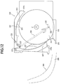
disc reproducing device 200, thedisc loading arm 220 is rotatably mounted on ashaft 221 secured to aninner frame 230. Adisc discharging arm 223 is rotatably mounted on ashaft 222 secured to theinner frame 230. Theloading arm 220 has aloading end 220a and aguide grooves 224 to be engaged with the periphery of thedisc 310. The dischargingarm 223 has a dischargingend 223a and aguide groove 225 to be engaged with the periphery of thedisc 310. Theloading arm 220 and the dischargingend 223a of the dischargingarm 223 are adapted to pass through theinlet 202. Each of the guide grooves has a width slightly larger than the thickness of thedisc 310. - On a lower portion of the
inner frame 230, aslider 234 having apush rod 233 is slidably mounted. When a selecteddisc 310 is reproduced in the reproducingdevice 200, theslider 234 is moved in the direction shown by an arrow and thepush rod 233 is engaged with acorresponding perforation 305 of the selected disc in thedisc holder 300. After reproduction, when the disc is returned to the stored position, theslider 234 is moved in the reverse direction so that thepush rod 233 is retracted from the perforation. - In order to load the
disc 310 to a center P (clamping position), aposition adjusting member 226 is rotatably mounted on an opposite surface of theinner frame 230 and urged in the direction a by a spring (not shown). Theposition adjusting member 226 has a pair ofprojections elliptic holes inner frame 230. - As shown in Fig. 10, when the
disc 310 engages with theprojections member 226 is rotated in the direction b against the spring force so that theprojections respective holes - In the device, two sizes of the discs can be loaded by the loading mechanism, for example the
disc 310 having the diameter of 12 cm and adisc 311 having the diameter of 8 cm. - The automatic changing operation of the disc will be described.
- When a
disc 310 to be reproduced is selected, one of thedisc reproducing devices 200 is moved along thewire 210 to the selected disc in theholder 300. Therollers 203 provided on the reproducingdevice 200 are rotated on thewire 210 which is not circulated, so that the only selected device can be freely moved. Since thewire 210 is horizontally expanded along thedisc holders 300, thediscs 310 mounted in the holders are prevented from removing. - The disc is selected in accordance with an address. A position sensor is mounted in the
device 200 for detecting an on/off signal by the detectingperforation 306 of theencoder 307. Thus, the position of the selected disc is detected by thedevice 200. - At the selected position, the
slider 234 in thedevice 200 is moved to the left of Fig. 9 so that thepush rod 233 is inserted into theperforation 305 corresponding to the selected disc. In thedisc holder 300, the blocking lugs 322 of theslide plate 320 close everyother perforations 305. Namely, there are no lugs on theperforations 305 corresponding to thespaces 304 storing the discs of the even numbers. On the other hand, the lugs close theperforations 305 corresponding to the discs of the odd numbers. Thus, when thepush rod 233 is abutted on thelug 322 through theperforation 305 at the odd number, the lug is pushed so that theslide plate 320 is slid against thespring 341. Thepin 324 of theslide plate 320 engaged with the cam slit 332 is slid to be engaged with thecam portion 333 so that themovable frame 330 is moved to the right in Fig. 5b. Thus, theguide projections 336 are moved by the one pitch of thespace 304 to open thespaces 304 where the discs of the odd numbers are stored. - The
loading end 220a of theloading arm 220 is inserted into a space between theprojections 336 and into thespace 304 between holdingplate 303. As hereinbefore described, the width of the entrance gap, that is, the distance between theapexes 336a of theguide projections 336 is twice as much as the pitch of thespace 304. Therefore, thearm 220 easily enters the gap between the apexes and engages with the disc. Even if thearm 220 deflects from the center, theend 220a of the arm abuts on one of theslants 336b of theguide projection 336 so that thearm 220 is guided by the slant to thespace 304. Thus, the arm can be exactly inserted into the space (Fig. 6). - It will be understood that the
loading arm 220 is inserted into thespace 304 for the disc of the even number without engaging with thelug 322 and hence without shifting theprojections 336. - A loading operation of the
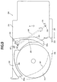
disc 310 of 12 cm for the automatic changer system will be described, first, with reference to Figs. 9, 11 and 12. - As shown in Fig. 9, at the selected position, the
loading arm 220 is rotated in the counterclockwise direction. Theloading end 220a is inserted into the space between theprojections 336 and into thespace 304. Theguide groove 224 is engaged with thedisc 310. Thearm 220 is further rotated so that the disc is removed from thespace 304 of theholder 300 and inserted into theinlet 210 of thedevice 200. The disc is engaged with theend 223a of the dischargingarm 223 in thedevice 200 and theguide groove 225 as shown in Fig. 11. - Both of the
arms disc 310 is engaged with theprojection 227 of theposition adjusting member 226 so that theprojection 227 is rotated in the direction b and engaged with thehole 231. Theprojection 228 engages with thehole 232, accordingly. As shown in Fig 12, the disc is loaded to the clamping position P. The disc is clamped to a turntable (not shown) by a clamper (not shown). In this state, since theend 220a of theloading arm 220 is disengaged from thedisc 310. The disc is reproduced without disturbed by the arm. - After reproduction, the
disc 310 is clamped to the position P and the dischargingarm 223 is rotated in the clockwise direction to engage theend 223a with the disc. The disc is pushed to be disengaged from theprojections member 226 is rotated in the direction a by the spring to be returned to the position. Theguide grooves inlet 202. Thus, the disc is stored in the holder. Theslider 234 is moved to disengage therod 233 from theperforation 305. - Consequently, the
slide plate 320 is slid by thespring 341 to return to the home position and hence themovable frame 330 is moved to return to the original position. - Describing a loading operation of the
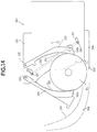
disc 311 of 8 cm with reference to Figs. 13, 14 and 15, the operation is approximately the same as thedisc 310. Namely, thearm 220 is rotated to engage thedisc 311 in thespace 304 at theend 220a so as to remove thedisc 311 from the space. Thedisc 311 is loaded in thedevice 200 through theinlet 202 by theend 220a and engaged with theend 223a of thearm 223 as shown in Fig. 14. Thedisc 311 is guided to the clamping position P by theends disc 311 is smaller than thedisc 310, thedisc 311 is not engaged with theprojection 227 of the adjustingmember 226. At the position P, thedisc 311 is engaged with theprojection 228 which is not rotated and held in the position P by theend 220a of thearm 220 and theprojection 228 as shown in Fig. 15. - When discharging the
disc 311, thedisc 311 is guided by theends 233a and 220a to be discharged from theinlet 202. - Referring to Fig. 16 showing the
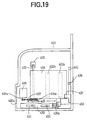
auxiliary disc holder 400, the holder comprises aleft frame member 420 and aright frame member 440. Avertical inlet 410 is formed between the left and right frame members corresponding to theinlet 112 of thedoor 110. On the side of theholder 400 corresponding to thedisc reproducing device 200, avertical space 401 is formed between the frame members. Theloading arm 220 of the reproducingdevice 200 can be inserted into thespace 401. - Referring to Figs. 18 and 19, the
left frame member 420 has a supportingmember 424 pivotally mounted on ashaft 423. The supportingmember 424 is urged to thespace 401. The supportingmember 424 has a pair ofrollers roller 422a (422b) is mounted in the inclined disposition. An upper end of theshaft 423 is rotatably engaged with asupport 435. A lower end of the shaft is secured to agear 425 having apulley 425a coaxial with thegear 425. Abelt 427 is provided between thepulley 425a and adrive shaft 426a of amotor 426. Themotor 426 is operated for loading the disc in theholder 400 when the disc is inserted into theinlet 410. Thegear 425 engages with agear 428 which engages with a gear (not shown) for rotatingrollers cam member 433 provided on a lower portion thereof. - The
left frame member 420 has ahole 420a corresponding to the reproducingdevice 200 to be engaged with thepush rod 233 of theslider 234. Aslider 430 is provide on the lower portion to be slidable in the direction shown by an arrow. Theslider 430 has a pair ofslits 431 andtapered end 430a engaged with thecam member 433 of the supportingmember 424. In theslit 431, apin 432 secured to the left frame member is engaged. - A
lock member 421 is rotatably mounted on ashaft 436 secured to theleft member 420 at theinlet 410 for preventing the disc from inserting into theinlet 410. Thelock member 421 has a lowerengaging portion 437 engaged with a lower end of the supportingmember 424 and an upper lock portion 438 (Fig. 17) to be projected on theinlet 410. - As shown in Fig. 21,
felts left frame member 420. - Fig. 22 shows the
right frame member 440. Theright member 440 has agrooves rollers left member 420, andfelts groove 444 is provided to be engaged with thelock portion 438 of thelock member 421. - The operation of the
auxiliary disc holder 400 will be described. - When the disc 310 (not shown) is inserted into the
inlets holder 400 detects it to drive themotor 426. Themotor 426 rotates thedrive shaft 426a to rotate thegear 425 through thebelt 427 and thepulley 425a. Thus, thegear 428 is rotated to rotate therollers disc 310 is loaded in theholder 400 and the lower portion of the disc is abutted on therollers member 424. When the disc is loaded on a predetermined position, themotor 426 stops. The disc is engaged with therollers felts 439a to 439c and 443a to 443c to be stably held in the holder. - It will be seen that length of the roller is determined to a half of the length of the
inlet 410. - In this state, if another disc is inserted into the
inlet 112, the periphery of that disc is engaged with the disc in the holder, so that the disc can not be inserted into the holder. - In reproducing operation, the reproducing
device 200 is moved to theholder 400 and thepush rod 233 of theslider 234 is inserted into thehole 420a to push theslider 430 to the right of Fig. 19. Thus, thetapered end 430a is engaged with thecam member 433 of the supportingmember 424 to urge the supportingmember 424 away from thespace 401. Thus, therollers member 424 is moved, the lower end thereof is abutted on the engagingportion 437 to rotate thelock member 421 in the clockwise direction of Fig. 17. Thus, theupper lock portion 438 is projected on theinlet 410. The disc is loaded in the reproducingdevice 200 by thearms - Fig. 23 shows a modification in which a single
disc reproducing device 200 is provided. As a further modification, three or more reproducing devices can be provided. - In place of the
rollers 203, a pin can be used. - The
projections 336 of the triangular prism in themovable frame 330 can be replaced in the other shape, such as a semi-cylindrical shape. - In accordance with the present invention, the width of the entrance gap for the loading arm is twice as much as the pitch of the space storing the disc, the loading arm is exactly inserted into the space through the gap, guided by the guide projections. Thus, the reproduction of a desired disc is ensured.
- Even if the position accuracy of the loading arm and the space is reduced, the loading of the disc is accurately operated.
- While the presently preferred embodiment of the present invention has been shown and described, it is to be understood that this disclosure is for the purpose of illustration and that various changes and modifications may be made without departing from the scope of the invention as set forth in the appended claims.
Claims (2)
- An automatic disc changer for a disc reproducing system comprising:a disc holder (300) having a plurality of holding plates (303) forming spaces (304) therebetween for storing a plurality of discs (310) in vertical position and a reproducing device (200),a panel (315) secured to the disc holder (300) , a plurality of guide apertures (305) being formed in the panel (315), arranged in the horizontal direction, each aperture positioned at a corresponding space (304),a slider (234) having a push rod (233) and being slidably mounted in the reproducing device (200) so that the push rod engages with one of the guide apertures, whereby the reproducing device is surely positioned with respect to the space (304).
- The automatic disc changer for a disc reproducing system according to Claim 1, wherein a plurality of detecting perforations (306) are provided, positioned at a corresponding space (304), and a position sensor is provided in the reproducing device (200) for detecting the position of the detecting perforation (306) of a selected disc.
Applications Claiming Priority (3)
| Application Number | Priority Date | Filing Date | Title |
|---|---|---|---|
| JP12594 | 1994-01-05 | ||
| JP00012594A JP3384856B2 (en) | 1994-01-05 | 1994-01-05 | Disc auto changer |
| EP95100017A EP0662687B1 (en) | 1994-01-05 | 1995-01-02 | Automatic disc changer for a disc reproducing system |
Related Parent Applications (1)
| Application Number | Title | Priority Date | Filing Date |
|---|---|---|---|
| EP95100017A Division EP0662687B1 (en) | 1994-01-05 | 1995-01-02 | Automatic disc changer for a disc reproducing system |
Publications (2)
| Publication Number | Publication Date |
|---|---|
| EP0924698A2 true EP0924698A2 (en) | 1999-06-23 |
| EP0924698A3 EP0924698A3 (en) | 2000-03-29 |
Family
ID=11465320
Family Applications (2)
| Application Number | Title | Priority Date | Filing Date |
|---|---|---|---|
| EP95100017A Expired - Lifetime EP0662687B1 (en) | 1994-01-05 | 1995-01-02 | Automatic disc changer for a disc reproducing system |
| EP99101213A Withdrawn EP0924698A3 (en) | 1994-01-05 | 1995-01-02 | Automatic disc changer for a disc reproducing system |
Family Applications Before (1)
| Application Number | Title | Priority Date | Filing Date |
|---|---|---|---|
| EP95100017A Expired - Lifetime EP0662687B1 (en) | 1994-01-05 | 1995-01-02 | Automatic disc changer for a disc reproducing system |
Country Status (4)
| Country | Link |
|---|---|
| US (1) | US5550801A (en) |
| EP (2) | EP0662687B1 (en) |
| JP (1) | JP3384856B2 (en) |
| DE (1) | DE69511122T2 (en) |
Cited By (3)
| Publication number | Priority date | Publication date | Assignee | Title |
|---|---|---|---|---|
| US10438629B2 (en) | 2016-02-17 | 2019-10-08 | International Business Machines Corporation | Disc storage cassettes comprising track connectors |
| US10529371B1 (en) | 2018-10-29 | 2020-01-07 | International Business Machines Corporation | Actuator tip calibration for robotic optical storage system |
| US10600441B1 (en) | 2018-12-07 | 2020-03-24 | International Business Machines Corporation | Disc gripper for storage discs |
Families Citing this family (18)
| Publication number | Priority date | Publication date | Assignee | Title |
|---|---|---|---|---|
| JP3113772B2 (en) * | 1994-01-05 | 2000-12-04 | パイオニア株式会社 | Disc auto changer |
| JP3090410B2 (en) * | 1995-09-12 | 2000-09-18 | 松下電器産業株式会社 | Disc changer device |
| JPH0991831A (en) * | 1995-09-20 | 1997-04-04 | Funai Electric Co Ltd | Disk auto-changer |
| JP3402888B2 (en) * | 1995-12-14 | 2003-05-06 | パイオニア株式会社 | Disk autochanger device |
| US5805787A (en) * | 1995-12-29 | 1998-09-08 | Emc Corporation | Disk based disk cache interfacing system and method |
| JP3406764B2 (en) * | 1996-02-06 | 2003-05-12 | パイオニア株式会社 | Auto disk changer device |
| US5936930A (en) * | 1996-04-17 | 1999-08-10 | Funai Electronic Co., Ltd. | Automatic disk changer |
| JPH09282771A (en) * | 1996-04-17 | 1997-10-31 | Funai Electric Co Ltd | Disk automatic changer |
| GB9617193D0 (en) * | 1996-08-16 | 1996-09-25 | Sound Leisure Ltd | Disc changer |
| US5912873A (en) * | 1997-06-18 | 1999-06-15 | Multidisc Technologies | Compact disc transporter with dual transport sites |
| US5886974A (en) * | 1997-06-18 | 1999-03-23 | Multidisc Technologies | Compact disc loader and transport apparatus |
| US5886960A (en) * | 1997-11-04 | 1999-03-23 | Multidisc Technologies | Optical disc system using multiple optical heads for accessing information data |
| JP2001148145A (en) * | 1999-11-19 | 2001-05-29 | Yamaha Corp | Disk holder and disk changer device |
| WO2010129906A2 (en) * | 2009-05-08 | 2010-11-11 | Powerfile, Inc. | Optical disc storage system |
| JP2014203483A (en) * | 2013-04-05 | 2014-10-27 | 日立コンシューマエレクトロニクス株式会社 | Optical disk library device |
| US9741389B1 (en) * | 2016-02-17 | 2017-08-22 | International Business Machines Corporation | High performance robotic optical storage system |
| US9672863B1 (en) | 2016-02-17 | 2017-06-06 | International Business Machines Corporation | Disc gripper for storage discs |
| US9741390B1 (en) | 2016-03-23 | 2017-08-22 | International Business Machines Corporation | Optical disc drive |
Citations (4)
| Publication number | Priority date | Publication date | Assignee | Title |
|---|---|---|---|---|
| US3662344A (en) * | 1970-09-24 | 1972-05-09 | Nsm Apparatebau Gmbh Kg | Automatic phonograph with pin memory unit and cam readout unit |
| JPS59213065A (en) * | 1983-05-17 | 1984-12-01 | Nec Corp | Goods carrying device |
| US4580254A (en) * | 1983-07-27 | 1986-04-01 | Victor Company Of Japan, Ltd. | Automatic disc selection type reproducing apparatus |
| EP0313110A2 (en) * | 1983-12-27 | 1989-04-26 | Kabushiki Kaisha Toshiba | Autochanger type disc player |
Family Cites Families (10)
| Publication number | Priority date | Publication date | Assignee | Title |
|---|---|---|---|---|
| US3009705A (en) * | 1957-10-10 | 1961-11-21 | Harting Elektro W | Mechanism for the preselection of gramophone records |
| JPS59231772A (en) * | 1983-06-13 | 1984-12-26 | Toshiba Corp | Automatic disk changing device |
| JPS6040563A (en) * | 1983-08-12 | 1985-03-02 | Pioneer Electronic Corp | Disk player |
| JPS6040559A (en) * | 1983-08-12 | 1985-03-02 | Pioneer Electronic Corp | Disk player |
| JPS60138789A (en) * | 1983-12-27 | 1985-07-23 | Toshiba Corp | Assembling method of magnetic head |
| JPH0821188B2 (en) * | 1983-12-27 | 1996-03-04 | 株式会社東芝 | Disc auto changer device |
| JPS61190753A (en) * | 1985-02-19 | 1986-08-25 | Toshiba Corp | Disk return device for disk selection type player |
| JPS6450274A (en) * | 1987-08-21 | 1989-02-27 | Pioneer Electronic Corp | Auto-changer type disk player |
| JPH04111277A (en) * | 1990-08-30 | 1992-04-13 | Matsushita Electric Ind Co Ltd | Disk magazine |
| JP3096334B2 (en) * | 1991-11-08 | 2000-10-10 | パイオニア株式会社 | Position detection device |
-
1994
- 1994-01-05 JP JP00012594A patent/JP3384856B2/en not_active Expired - Fee Related
-
1995
- 1995-01-02 DE DE69511122T patent/DE69511122T2/en not_active Expired - Fee Related
- 1995-01-02 EP EP95100017A patent/EP0662687B1/en not_active Expired - Lifetime
- 1995-01-02 EP EP99101213A patent/EP0924698A3/en not_active Withdrawn
- 1995-01-05 US US08/368,913 patent/US5550801A/en not_active Expired - Lifetime
Patent Citations (4)
| Publication number | Priority date | Publication date | Assignee | Title |
|---|---|---|---|---|
| US3662344A (en) * | 1970-09-24 | 1972-05-09 | Nsm Apparatebau Gmbh Kg | Automatic phonograph with pin memory unit and cam readout unit |
| JPS59213065A (en) * | 1983-05-17 | 1984-12-01 | Nec Corp | Goods carrying device |
| US4580254A (en) * | 1983-07-27 | 1986-04-01 | Victor Company Of Japan, Ltd. | Automatic disc selection type reproducing apparatus |
| EP0313110A2 (en) * | 1983-12-27 | 1989-04-26 | Kabushiki Kaisha Toshiba | Autochanger type disc player |
Non-Patent Citations (1)
| Title |
|---|
| PATENT ABSTRACTS OF JAPAN vol. 009, no. 083 (P-348), 12 April 1985 (1985-04-12) & JP 59 213065 A (NIPPON DENKI KK), 1 December 1984 (1984-12-01) * |
Cited By (5)
| Publication number | Priority date | Publication date | Assignee | Title |
|---|---|---|---|---|
| US10438629B2 (en) | 2016-02-17 | 2019-10-08 | International Business Machines Corporation | Disc storage cassettes comprising track connectors |
| US10580451B2 (en) | 2016-02-17 | 2020-03-03 | International Business Machines Corporation | Disc storage cassettes comprising index features |
| US10529371B1 (en) | 2018-10-29 | 2020-01-07 | International Business Machines Corporation | Actuator tip calibration for robotic optical storage system |
| US10692526B2 (en) | 2018-10-29 | 2020-06-23 | International Business Machines Corporation | Actuator tip calibration for robotic optical storage system |
| US10600441B1 (en) | 2018-12-07 | 2020-03-24 | International Business Machines Corporation | Disc gripper for storage discs |
Also Published As
| Publication number | Publication date |
|---|---|
| JPH07210972A (en) | 1995-08-11 |
| EP0924698A3 (en) | 2000-03-29 |
| JP3384856B2 (en) | 2003-03-10 |
| US5550801A (en) | 1996-08-27 |
| EP0662687B1 (en) | 1999-08-04 |
| DE69511122T2 (en) | 2000-04-06 |
| DE69511122D1 (en) | 1999-09-09 |
| EP0662687A1 (en) | 1995-07-12 |
Similar Documents
| Publication | Publication Date | Title |
|---|---|---|
| EP0662687B1 (en) | Automatic disc changer for a disc reproducing system | |
| US6314073B2 (en) | Disc drive apparatus with insertion error inhibit means for recording media having different structures | |
| KR100536103B1 (en) | Changer device for information disc | |
| US6373795B2 (en) | Apparatus for reproducing an optical disc | |
| KR910006084B1 (en) | Disk auto-changer | |
| US6167015A (en) | Apparatus for loading discs of different sizes | |
| US6480453B2 (en) | Apparatus and method for driving an optical disc with a caddy having a cover | |
| EP0662686B1 (en) | Automatic disc changer for a disc reproducing system | |
| US6934225B2 (en) | Disc cartridge and disc recording and/or reproducing apparatus | |
| US6222816B1 (en) | Disc reproducing device | |
| US6473372B2 (en) | Disc changer for a disc player | |
| KR100558719B1 (en) | Changer device for information disc | |
| US6493294B1 (en) | Disc reproducing device | |
| US6337843B2 (en) | Disc changer for a disc player | |
| US6680882B2 (en) | System for reproducing a disc | |
| JP2906993B2 (en) | Disc loading mechanism | |
| KR0139966Y1 (en) | Disk reproducing device | |
| JPH0231371A (en) | Multi-magazine disk player | |
| JP2625037B2 (en) | Adapter for small diameter discs in magazines for disc changers | |
| JP3613012B2 (en) | Disc changer device | |
| WO2005027114A1 (en) | Disk drive | |
| JPH052812A (en) | Disk player | |
| JPH02227863A (en) | Magazine holder for disk player with magazine changer | |
| JPH11191260A (en) | Disk exchanging device | |
| JPH0231367A (en) | Multi-magazine disk player |
Legal Events
| Date | Code | Title | Description |
|---|---|---|---|
| PUAI | Public reference made under article 153(3) epc to a published international application that has entered the european phase |
Free format text: ORIGINAL CODE: 0009012 |
|
| AC | Divisional application: reference to earlier application |
Ref document number: 662687 Country of ref document: EP |
|
| AK | Designated contracting states |
Kind code of ref document: A2 Designated state(s): DE FR GB |
|
| PUAL | Search report despatched |
Free format text: ORIGINAL CODE: 0009013 |
|
| AK | Designated contracting states |
Kind code of ref document: A3 Designated state(s): DE FR GB |
|
| 17P | Request for examination filed |
Effective date: 20000428 |
|
| 17Q | First examination report despatched |
Effective date: 20020425 |
|
| STAA | Information on the status of an ep patent application or granted ep patent |
Free format text: STATUS: THE APPLICATION IS DEEMED TO BE WITHDRAWN |
|
| 18D | Application deemed to be withdrawn |
Effective date: 20020906 |