US6337843B2 - Disc changer for a disc player - Google Patents

Disc changer for a disc player Download PDF

Info

Publication number
US6337843B2
US6337843B2 US09/289,657 US28965799A US6337843B2 US 6337843 B2 US6337843 B2 US 6337843B2 US 28965799 A US28965799 A US 28965799A US 6337843 B2 US6337843 B2 US 6337843B2
Authority
US
United States
Prior art keywords
disc
trays
tray
operating member
space
Prior art date
Legal status (The legal status is an assumption and is not a legal conclusion. Google has not performed a legal analysis and makes no representation as to the accuracy of the status listed.)
Expired - Fee Related
Application number
US09/289,657
Other versions
US20010043551A1 (en
Inventor
Susumu Yoshida
Toru Suzuki
Tomomichi Kimura
Kenjiro Ido
Takashi Mizoguchi
Kenji Uchiyama
Current Assignee (The listed assignees may be inaccurate. Google has not performed a legal analysis and makes no representation or warranty as to the accuracy of the list.)
Pioneer Corp
Original Assignee
Pioneer Electronic Corp
Priority date (The priority date is an assumption and is not a legal conclusion. Google has not performed a legal analysis and makes no representation as to the accuracy of the date listed.)
Filing date
Publication date
Application filed by Pioneer Electronic Corp filed Critical Pioneer Electronic Corp
Assigned to PIONEER ELECTRONIC CORPORATION reassignment PIONEER ELECTRONIC CORPORATION ASSIGNMENT OF ASSIGNORS INTEREST (SEE DOCUMENT FOR DETAILS). Assignors: IDO, KENJIRO, KIMURA, TOMOMICHI, MIZOGUCHI, TAKASHI, SUZUKI, TORU, UCHIYAMA, KENJI, YOSHIDA, SUSUMU
Publication of US20010043551A1 publication Critical patent/US20010043551A1/en
Application granted granted Critical
Publication of US6337843B2 publication Critical patent/US6337843B2/en
Anticipated expiration legal-status Critical
Expired - Fee Related legal-status Critical Current

Links

Images

Classifications

    • GPHYSICS
    • G11INFORMATION STORAGE
    • G11BINFORMATION STORAGE BASED ON RELATIVE MOVEMENT BETWEEN RECORD CARRIER AND TRANSDUCER
    • G11B17/00Guiding record carriers not specifically of filamentary or web form, or of supports therefor
    • G11B17/02Details
    • G11B17/021Selecting or spacing of record carriers for introducing the heads
    • GPHYSICS
    • G11INFORMATION STORAGE
    • G11BINFORMATION STORAGE BASED ON RELATIVE MOVEMENT BETWEEN RECORD CARRIER AND TRANSDUCER
    • G11B17/00Guiding record carriers not specifically of filamentary or web form, or of supports therefor
    • G11B17/22Guiding record carriers not specifically of filamentary or web form, or of supports therefor from random access magazine of disc records
    • G11B17/30Guiding record carriers not specifically of filamentary or web form, or of supports therefor from random access magazine of disc records wherein the playing unit is moved according to the location of the selected record

Definitions

  • the present invention relates to an optical disc changer for automatically changing a disc to another disc instructed by a user.
  • disc changer having disc storage in which a plurality of discs are arranged therein.
  • the device has a disc separating device for forming a space between the discs. A disc player is inserted in the space for reproducing a selected disc.
  • the disc storage is moved over the full height of storage in order to select a desired disc. As a result, the height of the device becomes large.
  • An object of the present invention is to provide a disc changer which may be reduced in size.
  • Another object of the present invention is to provide a disc changer in which the disc player and the disc separating device can be accurately positioned at a desired disc.
  • a disc changer comprising, a disc storage, a plurality of trays, each for holding a disc, arranged in a disc arranging direction in the disc storage and slidably held in the storage, a movable member provided to be moved in the disc arranging direction, first driving means for moving the movable member in the disc arranging direction, a disc player mounted on the movable member, a tray moving member mounted on the movable member and provided to be engaged with trays for moving the trays and for forming spaces between trays for receiving disc player, second driving means for moving the disc player between a retracted position and a disc reproducing position.
  • the trays are stacked in the storage.
  • the tray moving member is rotatably mounted on the movable member, and has a plurality of cams to be engaged with trays for raising the trays and for forming spaces between trays.
  • the first driving means comprises a pair of slide plates, each slide plate has at least one inclined hole having a plurality of steps corresponding the member of the trays, a pin secured to the movable member and engaged with the inclined hole, and means for sliding the slide plate.
  • the disc player is pivotally mounted on the movable member, and the second driving means is provided for rotating the disc player.
  • FIG. 1 is a perspective view of a disc changer according to the present invention
  • FIGS. 2 a , 2 b and 3 are plan views of a part of the disc changer
  • FIG. 4 is a side view of a tray stack
  • FIG. 5 is a front view of the disc changer
  • FIG. 6 is a side view of a driving roller
  • FIG. 7 a is a plan view showing a disc player
  • FIG. 7 b is a plan view showing a clamper
  • FIG. 8 is a side view showing a turntable
  • FIG. 9 is a plan view showing the operation of the disc player.
  • FIG. 10 is a plan view showing a chassis
  • FIG. 11 is a side view showing a slide plate
  • FIG. 12 is a side view showing a disc separating member
  • FIGS. 13 to 19 are side views showing the operation of the disc changer.
  • main composition of the device comprises a disc carrier 100 having a pair of driving rollers 101 , a disc player 200 having a turntable 201 , clamper 202 , pickup 203 , a disc storage 300 having six trays 301 (FIG. 2) for arranging discs in the Z-direction and a tray moving mechanism having a movable plate 400 for moving the tray 301 .
  • a chassis 1 main composition of the device.
  • the disc carrier 100 is provided for carrying a disc inserted from an opening by a user to the disc storage 300 , and for discharging the disc in the storage 300 .
  • the driving rollers 101 are provided to contact with the underside of the inserted disc and to carry it in the X-direction.
  • the tray 301 has a disc supporting plate 301 a having a V-shaped notch 301 b and a pair of notches 301 c .
  • the turntable 201 , clamper 202 and pickup 203 are inserted.
  • the tray 301 has a pair of holes 301 d in which guide shafts 2 are inserted, a pair of disc holding members 301 e , four projections 301 f.
  • the shaft 2 is inserted in the holes 301 d of six trays 301 and a hole of a regulating plate 302 on the stack of trays, thereby arranging the trays in the Z-direction.
  • the regulating plate 302 is urged by springs 303 provided inside wall of the chassis 1 so that regulating plate 302 is prevented from upwardly moving.
  • the regulating plate 302 has a vertical member 302 a to hold the trays, thereby preventing the trays from moving in the Y-direction.
  • a worm wheel 101 a is formed on a side of each driving roller 101 .
  • the driving roller 101 is rotatably mounted on an upright plate 103 a of a supporting plate 103 .
  • a disc path regulating plate 106 is provided above the driving roller 101 and rotatably supported by a shaft 103 b .
  • a disc carrying path 102 is formed between the plate 106 and the driving roller 101 .
  • a coil spring 107 is provided between the regulating plate 106 and the supporting plate 103 to urge the plate 106 toward the driving roller 101 .
  • a pair of rotatable shaft 105 are rotatably mounted on shafts 104 .
  • An upper portion of the rotatable shaft 105 is supported by the supporting plate 103 and a worm 105 is formed on an upper most portion of the rotatable shaft.
  • the worm 105 is engaged with the worm wheel 101 a of the driving roller 101 .
  • a pulley 105 a is formed on one of the rotatable shaft 105 , which pulley 105 a engages with a belt 109 of a motor 108 (FIG. 2 ); Both rotatable shafts 105 have pulleys and are connected by a belt (not shown). Thus, both the shafts 105 are rotated by the motor 108 through the belts.
  • Each supporting plate 103 has a downwardly projecting projection 103 c , passing through a hole formed in a movable plate 400 .
  • a movable member 110 is slidably mounted on the chassis 1 and engaged with the projection 103 c . Therefore, when the movable member 110 moves in the X-direction, each of the plates 103 is rotated about the shaft 104 to rotate the driving roller 101 about the shaft 104 .
  • FIG. 2 a shows the driving roller 101 at the disc carrying position
  • FIG. 2 b shows the one at the retracted position.
  • rollers 101 When the driving rollers 101 are located at the disc carrying position, the rollers are inserted in the notches 301 c as shown in FIG. 2 a . At the positions, rollers are positioned in the Y-direction, where the rollers are parallel with the roller insertion opening and located on the disc mounted on the disc supporting plate 301 a.
  • the driving rollers 101 at the retracted position are positioned outside the notches 301 c as shown in FIG. 2 b.
  • FIGS. 7 a to 9 show the disc player 200 and the disc moving mechanism.
  • On a base 200 a of the disc player 200 there is provided the turntable 201 , pickup 203 , and pickup moving mechanism 204 .
  • the base 200 a is rotatably supported by a shaft 401 on the movable plate 400 .
  • a clamper base 205 is rotatably supported by a shaft 200 b on the base 200 a and holds the clamper 202 at an end portion.
  • a restriction portion 205 a is formed on the clamper base 205 .
  • the clamper base 205 is urged to the base 200 a by a spring 206 mounted on the shaft 200 b.
  • a cramper operation member 207 is provided on the base 200 a .
  • a pair of elongated holes 207 a there is provided a pair of elongated holes 207 a , an elongated hole 207 b perpendicular with the holes 207 a , and a roller 207 c .
  • engaged is a pin 200 c projected from the base 200 a , so that the member 207 is movable in the axis direction of a shaft 200 b on the base 200 a.
  • the movable plate 400 has an arcuated hole 402 in which a movable pin 3 is inserted.
  • the pin 3 is further engaged with the elongated hole 207 b .
  • the pin 3 is moved in the arcuated hole 402 by a driving mechanism (not shown).
  • the movement of the pin 3 causes the movement of the disc player between the reproduction position and the retracted position and the disc clamping operation.
  • the disc player 200 is at the retracted position, where the restriction portion 205 a of the clamper base 205 is mounted on the roller 207 c of the clamp operating member 207 , thereby releasing the clamper 202 from the turntable 201 .
  • the driving direction of the pin 3 becomes parallel with the longitudinal direction of the elongated holes 207 a of the operating member 207 . Therefore, only the operating member 207 is moved in the longitudinal direction with respect to the base 200 a , so that the restriction portion 205 a of the base 205 removes from the roller 207 c . As a result, the clamper 202 is pressed against the turntable 201 by the coil spring 206 .
  • the disc clamp operation is carried out with the movement of the disc player 200 from the retracted position to the reproduction position, and the clamping is done at the same time as the positioning of the disc player 200 to the reproducing position.
  • the clamp is released when the disc player moves from the reproduction position to the retracted position.
  • an arm 4 is rotatably supported by a shaft 4 a at the underside of the chassis 1 .
  • the arm is adapted to be pivoted by a motor (not shown).
  • a pair of vertical guide plates 1 a are formed on both sides of the chassis 1 , in the Z-direction.
  • Slide plates 5 and 6 are slidably attached on the guide plates 1 a .
  • the slide plates 5 and 6 have projections 5 a , 6 a at the lower ends thereof, which projections are pivotally connected to both ends of the arm 4 . Therefore, when the arm 4 is pivoted, the slide plates are moved in the opposite directions.
  • the slide plate 6 has a pair of holes 6 b in the X-direction, each of the holes 6 b slidably engages with a pin 1 c on the guide plate 1 a .
  • the slide plate 5 has also the same holes as 6 b .
  • Each guide plate 1 a has a vertical guide hole 1 b in which slidably engaged is a pin 400 c provided on a vertical plate 400 b of the movable plate 400 .
  • the pin 400 c is slidably engaged with a step wisely inclined heaving hole 6 c formed in the slide plate 6 .
  • the slide plate 5 has also heaving hole inclined in the reverse direction to the hole 6 c .
  • four pins 400 c engage with the heaving holes and are moved in the Z-direction when the slide plates 5 and 6 moves in the X-direction, which causes the movable plate 400 to vertically move.
  • the heaving hole has six steps which corresponds to the six trays.
  • FIG. 12 shows one of four tray moving members 410 which are pivotally mounted on the vertical plate 400 b at a shaft 410 a .
  • a projection 410 b is slidably engaged with an arcuated groove 400 d formed in the vertical plate 400 b .
  • the tray moving member 410 has an L-shaped hole 410 c in which a projection 301 f (FIG. 3) of the tray 301 .
  • FIGS. 13 through 17 show the operation for mounting a disc inserted from the opening on the tray 301 of the disc storage 300 .
  • the operation is described about the mounting of the inserted disc on the second tray from the lower most tray.
  • FIG. 13 shows a waiting state. In the state, all trays are stacked up.
  • the pin 400 c is mounted on the lower most step of the inclined hole 6 c , and the movable plate 400 is positioned at the lower most position.
  • the tray moving member 410 is retracted from the tray 310 so that the tray moving member does not strike the tray when the movable plate 400 moves.
  • the slide member 6 When the user inserts a disc in the opening, the slide member 6 is moved to the left and the slide member 5 is moved to the right by the arm 4 to raise the movable plate 400 .
  • the slide member 6 (the description about the slide member will be omitted hereinafter) stops to stop the movable plate 400 .
  • the tray moving member 410 holds the second tray 301 , engaging with the underside of the tray.
  • the tray moving member 410 is rotated in the clockwise direction, so that the cam 410 d raises the projection 301 f of the third tray, thereby lifting the third through sixth trays.
  • the projection 301 f of the second tray mounts on the cam 410 e and enters the hole 410 c .
  • the second tray is held by the tray moving member 410 .
  • the slide member 6 is moved to the left to lift the movable plate 400 . Therefore, the third to sixth trays are raised by the cam 410 d , and the second tray is raised by the cam 410 e , leaving the first tray.
  • the slide member 6 stops.
  • the second tray held by the tray moving member 410 is placed at a position corresponding to the upper most tray position before the lifting shown in FIG. 13 .
  • This position corresponds to the position of the driving roller 101 of the disc carrier 100 (FIG. 5 ), where the insertion and discharge of the disc are performed at the height.
  • the tray moving member 410 is slightly rotated in the clockwise direction, so that the third through sixth trays are raised by the cam 410 d although the second tray is not raised.
  • the driving roller 101 is moved from the retracted position (FIG. 2 b ) to the disc carrying position (FIG. 2 a ).
  • the driving roller 101 is driven so that the disc inserted by the user is carried.
  • the driving roller 101 is stopped.
  • the driving roller 101 is moved from the disc carrying position to the retracted position. At that time, the driving roller moves while rotated in the disc feeding direction. Therefore, the disc is not moved to the retracted position.
  • the driving roller reaches to the retracted position, the disc is released from the roller, so that disc falls on a holding surface 301 a (FIG. 2 b ) of the second tray.
  • the slide member 6 is moved to lower the movable plate 400 .
  • the pin 400 c reaches the second step, the slide member 6 is stopped. Therefore, the plate 400 is positioned at the position shown in FIG. 14 .
  • the tray moving member 410 is rotated in the counterclockwise direction so that cams 410 d and 410 e are released from the projections 301 f of the trays.
  • the slide member 6 is further moved.
  • the pin 400 c reaches the lower most step, the slide member is stopped.
  • the operation for discharging disc is the same as the above described operation except the rotating of the driving roller 101 in the disc discharge direction.
  • the movable plate 400 is raised so that the tray moving member 410 and the disc player 200 are positioned at the second tray.
  • a space for inserting the disc player 200 is formed between the second tray and the third tray, by the rotation of the tray moving member 410 in the clockwise direction, which operation is the same manner as above description as shown in FIG. 14 .
  • the tray moving member 410 is further rotated in the clockwise direction, so that the third to sixth trays are moreover raised from the position of FIG. 14 .
  • the second tray is raised by the cam 410 f .
  • the first tray is pressed by the outside of the cam 410 e , thereby prevented from moving.
  • a large space is formed under the second tray, so that the player 200 can be inserted.
  • the projection 301 f of the second tray is deeply inserted in the hole 410 c to be held by the tray moving member 410 .
  • the disc player 200 is moved from retracted position to the reproduction position in the above described spaces by the player moving mechanism as shown in FIG. 9 .
  • the clamper 202 and the turntable 201 are separated from each other as shown in FIG. 18 .
  • the clamper 202 is lowered to clamp the disc on the turntable 201 .
  • the tray moving member 410 is slightly rotated in the counterclockwise direction to lower the second tray. Therefore, the disc on the second tray is clamped by the clamper and the turntable as shown in FIG. 19 .
  • the disc separating member for forming a space between the disc and the disc player to be inserted in the space are moved together. Therefore, the height of the disc changer can be reduced compared with the device in which the whole of the disc storage is moved.
  • both the devices can be accurately positioned at a desired disc.

Landscapes

  • Automatic Disk Changers (AREA)

Abstract

A disc storage is provided for storing a plurality of trays, each for holding a disc. The trays are stacked in the storage. A movable member is provided to be moved in the vertical direction. A disc player, a tray moving device are mounted on the movable member. The tray moving device is provided to be engaged with trays for moving the trays and for forming spaces between trays for receiving disc player. A driving device is provided for vertically moving the movable member.

Description

BACKGROUND OF THE INVENTION
The present invention relates to an optical disc changer for automatically changing a disc to another disc instructed by a user.
There is used a disc changer having disc storage in which a plurality of discs are arranged therein.
The device has a disc separating device for forming a space between the discs. A disc player is inserted in the space for reproducing a selected disc.
In the conventional disc changer, the disc storage is moved over the full height of storage in order to select a desired disc. As a result, the height of the device becomes large.
In addition, it is necessary to accurately position the desired disc, disc player and disc separating device in order to reproduce the desired disc. However, it is difficult to accurately position those devices.
SUMMARY OF THE INVENTION
An object of the present invention is to provide a disc changer which may be reduced in size.
Another object of the present invention is to provide a disc changer in which the disc player and the disc separating device can be accurately positioned at a desired disc.
According to the present invention, there is provided a disc changer comprising, a disc storage, a plurality of trays, each for holding a disc, arranged in a disc arranging direction in the disc storage and slidably held in the storage, a movable member provided to be moved in the disc arranging direction, first driving means for moving the movable member in the disc arranging direction, a disc player mounted on the movable member, a tray moving member mounted on the movable member and provided to be engaged with trays for moving the trays and for forming spaces between trays for receiving disc player, second driving means for moving the disc player between a retracted position and a disc reproducing position.
The trays are stacked in the storage.
The tray moving member is rotatably mounted on the movable member, and has a plurality of cams to be engaged with trays for raising the trays and for forming spaces between trays.
The first driving means comprises a pair of slide plates, each slide plate has at least one inclined hole having a plurality of steps corresponding the member of the trays, a pin secured to the movable member and engaged with the inclined hole, and means for sliding the slide plate.
The disc player is pivotally mounted on the movable member, and the second driving means is provided for rotating the disc player.
These and other objects and features of the present invention will become more apparent from the following detailed description with reference to the accompanying drawings.
BRIEF DESCRIPTION OF DRAWINGS
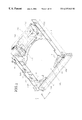
FIG. 1 is a perspective view of a disc changer according to the present invention;
FIGS. 2a, 2 b and 3 are plan views of a part of the disc changer;
FIG. 4 is a side view of a tray stack;
FIG. 5 is a front view of the disc changer;
FIG. 6 is a side view of a driving roller;
FIG. 7a is a plan view showing a disc player;
FIG. 7b is a plan view showing a clamper;
FIG. 8 is a side view showing a turntable;
FIG. 9 is a plan view showing the operation of the disc player;
FIG. 10 is a plan view showing a chassis;
FIG. 11 is a side view showing a slide plate;
FIG. 12 is a side view showing a disc separating member; and
FIGS. 13 to 19 are side views showing the operation of the disc changer.
DETAILED DESCRIPTION OF THE PREFERRED EMBODIMENT
Referring to FIGS. 1, 2 a and 2 b showing the disc changer according to the present invention, main composition of the device comprises a disc carrier 100 having a pair of driving rollers 101, a disc player 200 having a turntable 201, clamper 202, pickup 203, a disc storage 300 having six trays 301 (FIG. 2) for arranging discs in the Z-direction and a tray moving mechanism having a movable plate 400 for moving the tray 301. These portions are provided in a chassis 1.
The disc carrier 100 is provided for carrying a disc inserted from an opening by a user to the disc storage 300, and for discharging the disc in the storage 300.
The driving rollers 101 are provided to contact with the underside of the inserted disc and to carry it in the X-direction.
Referring to FIG. 3, the tray 301 has a disc supporting plate 301 a having a V-shaped notch 301 b and a pair of notches 301 c. In the notch 301 b, the turntable 201, clamper 202 and pickup 203 are inserted. Furthermore, the tray 301 has a pair of holes 301 d in which guide shafts 2 are inserted, a pair of disc holding members 301 e, four projections 301 f.
As shown in FIG. 4, the shaft 2 is inserted in the holes 301 d of six trays 301 and a hole of a regulating plate 302 on the stack of trays, thereby arranging the trays in the Z-direction. The regulating plate 302 is urged by springs 303 provided inside wall of the chassis 1 so that regulating plate 302 is prevented from upwardly moving. The regulating plate 302 has a vertical member 302 a to hold the trays, thereby preventing the trays from moving in the Y-direction.
Referring to FIGS. 5 and 6 showing the disc carrier 100, a worm wheel 101 a is formed on a side of each driving roller 101. The driving roller 101 is rotatably mounted on an upright plate 103 a of a supporting plate 103. A disc path regulating plate 106 is provided above the driving roller 101 and rotatably supported by a shaft 103 b. Between the plate 106 and the driving roller 101, a disc carrying path 102 is formed. A coil spring 107 is provided between the regulating plate 106 and the supporting plate 103 to urge the plate 106 toward the driving roller 101.
A pair of rotatable shaft 105 are rotatably mounted on shafts 104. An upper portion of the rotatable shaft 105 is supported by the supporting plate 103 and a worm 105 is formed on an upper most portion of the rotatable shaft. The worm 105 is engaged with the worm wheel 101 a of the driving roller 101. A pulley 105 a is formed on one of the rotatable shaft 105, which pulley 105 a engages with a belt 109 of a motor 108 (FIG. 2); Both rotatable shafts 105 have pulleys and are connected by a belt (not shown). Thus, both the shafts 105 are rotated by the motor 108 through the belts.
Each supporting plate 103 has a downwardly projecting projection 103 c, passing through a hole formed in a movable plate 400. A movable member 110 is slidably mounted on the chassis 1 and engaged with the projection 103 c. Therefore, when the movable member 110 moves in the X-direction, each of the plates 103 is rotated about the shaft 104 to rotate the driving roller 101 about the shaft 104.
Due to the above described construction, the driving rollers 101 are moved between a disc carrying position and a retracted position. FIG. 2a shows the driving roller 101 at the disc carrying position, and FIG. 2b shows the one at the retracted position.
When the driving rollers 101 are located at the disc carrying position, the rollers are inserted in the notches 301 c as shown in FIG. 2a. At the positions, rollers are positioned in the Y-direction, where the rollers are parallel with the roller insertion opening and located on the disc mounted on the disc supporting plate 301 a.
The driving rollers 101 at the retracted position are positioned outside the notches 301 c as shown in FIG. 2b.
FIGS. 7a to 9 show the disc player 200 and the disc moving mechanism. On a base 200 a of the disc player 200, there is provided the turntable 201, pickup 203, and pickup moving mechanism 204. The base 200 a is rotatably supported by a shaft 401 on the movable plate 400. A clamper base 205 is rotatably supported by a shaft 200 b on the base 200 a and holds the clamper 202 at an end portion. A restriction portion 205 a is formed on the clamper base 205. The clamper base 205 is urged to the base 200 a by a spring 206 mounted on the shaft 200 b.
On the base 200 a, a cramper operation member 207 is provided. There is provided a pair of elongated holes 207 a, an elongated hole 207 b perpendicular with the holes 207 a, and a roller 207 c. In each hole 207 a, engaged is a pin 200 c projected from the base 200 a, so that the member 207 is movable in the axis direction of a shaft 200 b on the base 200 a.
The movable plate 400 has an arcuated hole 402 in which a movable pin 3 is inserted. The pin 3 is further engaged with the elongated hole 207 b. The pin 3 is moved in the arcuated hole 402 by a driving mechanism (not shown).
The movement of the pin 3 causes the movement of the disc player between the reproduction position and the retracted position and the disc clamping operation.
In FIG. 7a, the disc player 200 is at the retracted position, where the restriction portion 205 a of the clamper base 205 is mounted on the roller 207 c of the clamp operating member 207, thereby releasing the clamper 202 from the turntable 201.
When the pin 3 is moved in the direction shown by the arrow, the operating member 207 and base 200 a are rotated about the shaft 401 in the clockwise direction. Thus, the disc player 200 is rotated to the reproduction position shown by dot and dash lines in FIG. 9.
Immediately before the reaching of the pin to the end of the arcuated hole 402, namely, immediately before the time when the disc player reaches the reproduction position, the driving direction of the pin 3 becomes parallel with the longitudinal direction of the elongated holes 207 a of the operating member 207. Therefore, only the operating member 207 is moved in the longitudinal direction with respect to the base 200 a, so that the restriction portion 205 a of the base 205 removes from the roller 207 c. As a result, the clamper 202 is pressed against the turntable 201 by the coil spring 206.
As described above, the disc clamp operation is carried out with the movement of the disc player 200 from the retracted position to the reproduction position, and the clamping is done at the same time as the positioning of the disc player 200 to the reproducing position. The clamp is released when the disc player moves from the reproduction position to the retracted position.
Referring to FIG. 10, an arm 4 is rotatably supported by a shaft 4 a at the underside of the chassis 1. The arm is adapted to be pivoted by a motor (not shown).
As shown in FIGS. 1, 10 and 11, a pair of vertical guide plates 1 a are formed on both sides of the chassis 1, in the Z-direction. Slide plates 5 and 6 are slidably attached on the guide plates 1 a. The slide plates 5 and 6 have projections 5 a, 6 a at the lower ends thereof, which projections are pivotally connected to both ends of the arm 4. Therefore, when the arm 4 is pivoted, the slide plates are moved in the opposite directions.
As shown in FIG. 11, the slide plate 6 has a pair of holes 6 b in the X-direction, each of the holes 6 b slidably engages with a pin 1 c on the guide plate 1 a. The slide plate 5 has also the same holes as 6 b. Each guide plate 1 a has a vertical guide hole 1 b in which slidably engaged is a pin 400 c provided on a vertical plate 400 b of the movable plate 400. Furthermore, the pin 400 c is slidably engaged with a step wisely inclined heaving hole 6 c formed in the slide plate 6. The slide plate 5 has also heaving hole inclined in the reverse direction to the hole 6 c. Thus, four pins 400 c engage with the heaving holes and are moved in the Z-direction when the slide plates 5 and 6 moves in the X-direction, which causes the movable plate 400 to vertically move.
The heaving hole has six steps which corresponds to the six trays.
FIG. 12 shows one of four tray moving members 410 which are pivotally mounted on the vertical plate 400 b at a shaft 410 a. A projection 410 b is slidably engaged with an arcuated groove 400 d formed in the vertical plate 400 b. The tray moving member 410 has an L-shaped hole 410 c in which a projection 301 f (FIG. 3) of the tray 301. There is formed four cams 410 d, 410 e, 410 f and 410 g which are engaged with the projections 301 f.
The operation of the device will be described hereinafter with reference to FIGS. 13 through 19. FIGS. 13 through 17 show the operation for mounting a disc inserted from the opening on the tray 301 of the disc storage 300. The operation is described about the mounting of the inserted disc on the second tray from the lower most tray.
FIG. 13 shows a waiting state. In the state, all trays are stacked up. The pin 400 c is mounted on the lower most step of the inclined hole 6 c, and the movable plate 400 is positioned at the lower most position. The tray moving member 410 is retracted from the tray 310 so that the tray moving member does not strike the tray when the movable plate 400 moves.
When the user inserts a disc in the opening, the slide member 6 is moved to the left and the slide member 5 is moved to the right by the arm 4 to raise the movable plate 400. When the pin 400 c reaches the second step as shown in FIG. 14, the slide member 6 (the description about the slide member will be omitted hereinafter) stops to stop the movable plate 400. At the position, the tray moving member 410 holds the second tray 301, engaging with the underside of the tray.
More particularly, the tray moving member 410 is rotated in the clockwise direction, so that the cam 410 d raises the projection 301 f of the third tray, thereby lifting the third through sixth trays.
On the other hand, the projection 301 f of the second tray mounts on the cam 410 e and enters the hole 410 c. Thus, the second tray is held by the tray moving member 410.
Next, the slide member 6 is moved to the left to lift the movable plate 400. Therefore, the third to sixth trays are raised by the cam 410 d, and the second tray is raised by the cam 410 e, leaving the first tray.
As shown in FIG. 15, when the pin 400 c reaches the upper most step, the slide member 6 stops. The second tray held by the tray moving member 410 is placed at a position corresponding to the upper most tray position before the lifting shown in FIG. 13. This position corresponds to the position of the driving roller 101 of the disc carrier 100 (FIG. 5), where the insertion and discharge of the disc are performed at the height.
As shown in FIG. 16, the tray moving member 410 is slightly rotated in the clockwise direction, so that the third through sixth trays are raised by the cam 410 d although the second tray is not raised. Thus, there is formed a space above the second tray, in which space the driving roller 101 can be inserted. Therefore, the driving roller 101 is moved from the retracted position (FIG. 2b) to the disc carrying position (FIG. 2a).
Thereafter, the driving roller 101 is driven so that the disc inserted by the user is carried. When the disc reaches the second tray, the driving roller 101 is stopped.
Next, as shown in FIG. 17, the driving roller 101 is moved from the disc carrying position to the retracted position. At that time, the driving roller moves while rotated in the disc feeding direction. Therefore, the disc is not moved to the retracted position. When the driving roller reaches to the retracted position, the disc is released from the roller, so that disc falls on a holding surface 301 a (FIG. 2b) of the second tray.
Thereafter, the slide member 6 is moved to lower the movable plate 400. When the pin 400 c reaches the second step, the slide member 6 is stopped. Therefore, the plate 400 is positioned at the position shown in FIG. 14. Furthermore, the tray moving member 410 is rotated in the counterclockwise direction so that cams 410 d and 410 e are released from the projections 301 f of the trays.
Next, the slide member 6 is further moved. When the pin 400 c reaches the lower most step, the slide member is stopped. Thus, the operation for carrying the disc to the tray finishes.
The operation for discharging disc is the same as the above described operation except the rotating of the driving roller 101 in the disc discharge direction.
The operation for reproducing the disc held on the tray will be described hereinafter.
In the waiting state shown in FIG. 13, when the reproduction of the disc held on the second disc is instructed, the movable plate 400 is raised so that the tray moving member 410 and the disc player 200 are positioned at the second tray.
Next, a space for inserting the disc player 200 is formed between the second tray and the third tray, by the rotation of the tray moving member 410 in the clockwise direction, which operation is the same manner as above description as shown in FIG. 14.
Thereafter, the tray moving member 410 is further rotated in the clockwise direction, so that the third to sixth trays are moreover raised from the position of FIG. 14. At the same time, the second tray is raised by the cam 410 f. On the other hand, the first tray is pressed by the outside of the cam 410 e, thereby prevented from moving. Thus, as shown in FIG. 18, a large space is formed under the second tray, so that the player 200 can be inserted. The projection 301 f of the second tray is deeply inserted in the hole 410 c to be held by the tray moving member 410.
Next, the disc player 200 is moved from retracted position to the reproduction position in the above described spaces by the player moving mechanism as shown in FIG. 9. At that time, the clamper 202 and the turntable 201 are separated from each other as shown in FIG. 18. When the player 200 is positioned at the reproduction position, the clamper 202 is lowered to clamp the disc on the turntable 201. At the same time, the tray moving member 410 is slightly rotated in the counterclockwise direction to lower the second tray. Therefore, the disc on the second tray is clamped by the clamper and the turntable as shown in FIG. 19.
In accordance with the present invention, the disc separating member for forming a space between the disc and the disc player to be inserted in the space are moved together. Therefore, the height of the disc changer can be reduced compared with the device in which the whole of the disc storage is moved.
Furthermore, since the disc separating member and the disc player are integrally provided, both the devices can be accurately positioned at a desired disc.
While the invention has been described in conjunction with preferred specific embodiment thereof, it will be understood that this description is intended to illustrate and not limit the scope of the invention, which is defined by the following claims.

Claims (3)

What is claimed is:
1. A disc changer comprising:
a disc storage unit;
a plurality of trays, each for holding a disc, arranged in a disc arranging direction in the disc storage unit and slidably held in the disc storage unit;
an operating member provided to be relatively moved with the plurality of trays in the disc arranging direction;
a first driving means for relatively moving the operating member with the plurality of trays;
a tray moving member mounted on the operating member wherein the tray moving member moves a selected one of the plurality of trays and an adjacent tray in the disc arranging direction forming a first space and a second space on opposite sides of the selected one of the plurality of trays; and
a second driving means for moving a part of a disc player into the second space,
wherein the disc arranging direction is a vertical direction, and the plurality of trays are stacked, and
wherein the tray moving member is rotatably mounted on the operating member, and has a plurality of cams to be provided for raising the plurality of trays and sequentially forming spaces between the plurality of trays, and further for engaging with the plurality of trays.
2. A disc changer comprising:
a disc storage unit;
a plurality of trays, each for holding a disc, arranged in a disc arranging direction in the disc storage unit and slidably held in the disc storage unit;
an operating member provided to be relatively moved with the plurality of trays in the disc arranging direction;
a first driving means for relatively moving the operating member with the plurality of trays;
a tray moving member mounted on the operating member wherein the tray moving member moves a selected one of the plurality of trays and an adjacent tray in the disc arranging direction forming a first space and a second space on opposite sides of the selected one of the plurality of trays; and
a second driving means for moving a part of a disc player into the second space,
wherein the disc arranging direction is a vertical direction, and the plurality of trays are stacked, and
wherein the first driving means comprises a pair of slidable plates, each slide plate has at least one inclined hole having a plurality of steps, the plurality of steps corresponding to a number of the trays, a pin secured to the operating member and engaged with the inclined hole, and means for sliding each slide plate.
3. A disc changer comprising:
a disc storage unit;
a plurality of trays, each for holding a disc, arranged in a disc arranging direction in the disc storage unit and slidably held in the disc storage unit;
an operating member provided to be relatively moved with the plurality of trays in the disc arranging direction;
a first driving means for relatively moving the operating member with the plurality of trays;
a tray moving member mounted on the operating member wherein the tray moving member moves a selected one of the plurality of trays and an adjacent tray in the disc arranging direction forming a first space and a second space on opposite sides of the selected one of the plurality of trays; and
a second driving means for moving a part of a disc player into the second space,
wherein the disc arranging direction is a vertical direction, and the plurality of trays are stacked, and
wherein the disc player is pivotally mounted on the operating member, and the second driving means is provided for rotating the disc player.
US09/289,657 1998-04-17 1999-04-12 Disc changer for a disc player Expired - Fee Related US6337843B2 (en)

Applications Claiming Priority (2)

Application Number Priority Date Filing Date Title
JP10726598A JP3624687B2 (en) 1998-04-17 1998-04-17 Disc player
JP10-107265 1998-04-17

Publications (2)

Publication Number Publication Date
US20010043551A1 US20010043551A1 (en) 2001-11-22
US6337843B2 true US6337843B2 (en) 2002-01-08

Family

ID=14454680

Family Applications (1)

Application Number Title Priority Date Filing Date
US09/289,657 Expired - Fee Related US6337843B2 (en) 1998-04-17 1999-04-12 Disc changer for a disc player

Country Status (4)

Country Link
US (1) US6337843B2 (en)
EP (1) EP0955633B1 (en)
JP (1) JP3624687B2 (en)
DE (1) DE69912513T2 (en)

Cited By (6)

* Cited by examiner, † Cited by third party
Publication number Priority date Publication date Assignee Title
US20020038260A1 (en) * 2000-09-28 2002-03-28 Kabushiki Kaisha Toshiba Semiconductor device, sales method for semiconductor device, sales system for semiconductor device and program product storing sales program for semiconductor device
US20030198147A1 (en) * 1999-09-28 2003-10-23 Sony Corporation Disc recording and/or reproducing device
US6654319B1 (en) * 1999-09-29 2003-11-25 Sony Corporation Disc recording and/or reproducing apparatus having control plates and space forming features
US20060242656A1 (en) * 2003-01-06 2006-10-26 Jisung Woo Changer for optical recording media
US20070247980A1 (en) * 2004-08-23 2007-10-25 Matsushita Electric Industrial Co., Ltd. Optical Disk Device
US20100095315A1 (en) * 2006-12-22 2010-04-15 Mitsubishi Electric Corporation Storage medium playback device

Families Citing this family (1)

* Cited by examiner, † Cited by third party
Publication number Priority date Publication date Assignee Title
CN101611446B (en) * 2007-02-08 2012-01-11 皇家飞利浦电子股份有限公司 Disk loading mechanism

Citations (7)

* Cited by examiner, † Cited by third party
Publication number Priority date Publication date Assignee Title
US5117409A (en) * 1990-02-09 1992-05-26 Pioneer Electronic Corporation Multidisk containing player including magazine having a housing with separable upper and lower half portions
EP0519069A1 (en) 1990-12-28 1992-12-23 Nkk Corporation Automatic disc selector
JPH06131792A (en) * 1992-10-20 1994-05-13 Fujitsu Ten Ltd Auto-changer for compact disk
US5508994A (en) * 1993-03-05 1996-04-16 Nakamichi Corporation Disk player with compact arrangement of a reader and disk storage magazine
US5793717A (en) * 1995-01-25 1998-08-11 Pioneer Electronic Corporation Information recording and reproducing apparatus and method of loading/unloading discs
US5917787A (en) * 1996-08-23 1999-06-29 Alpine Electronics, Inc. Disk player
US5970041A (en) * 1996-07-15 1999-10-19 Sony Corporation Disc changer device increasing the distance between a gripped disc and neighboring discs on both sides of the gripped disc

Family Cites Families (1)

* Cited by examiner, † Cited by third party
Publication number Priority date Publication date Assignee Title
DE19725169B4 (en) * 1996-06-13 2011-01-27 Fujitsu Ten Ltd., Kobe-shi Disc-shaped record carrier reproducing apparatus

Patent Citations (7)

* Cited by examiner, † Cited by third party
Publication number Priority date Publication date Assignee Title
US5117409A (en) * 1990-02-09 1992-05-26 Pioneer Electronic Corporation Multidisk containing player including magazine having a housing with separable upper and lower half portions
EP0519069A1 (en) 1990-12-28 1992-12-23 Nkk Corporation Automatic disc selector
JPH06131792A (en) * 1992-10-20 1994-05-13 Fujitsu Ten Ltd Auto-changer for compact disk
US5508994A (en) * 1993-03-05 1996-04-16 Nakamichi Corporation Disk player with compact arrangement of a reader and disk storage magazine
US5793717A (en) * 1995-01-25 1998-08-11 Pioneer Electronic Corporation Information recording and reproducing apparatus and method of loading/unloading discs
US5970041A (en) * 1996-07-15 1999-10-19 Sony Corporation Disc changer device increasing the distance between a gripped disc and neighboring discs on both sides of the gripped disc
US5917787A (en) * 1996-08-23 1999-06-29 Alpine Electronics, Inc. Disk player

Cited By (11)

* Cited by examiner, † Cited by third party
Publication number Priority date Publication date Assignee Title
US20030198147A1 (en) * 1999-09-28 2003-10-23 Sony Corporation Disc recording and/or reproducing device
US6751181B1 (en) * 1999-09-28 2004-06-15 Sony Corporation Recording and/or reproducing device for disks
US6760283B2 (en) * 1999-09-28 2004-07-06 Sony Corporation Disk recording and/or reproducing device with starting and ejection control means
US6654319B1 (en) * 1999-09-29 2003-11-25 Sony Corporation Disc recording and/or reproducing apparatus having control plates and space forming features
US20020038260A1 (en) * 2000-09-28 2002-03-28 Kabushiki Kaisha Toshiba Semiconductor device, sales method for semiconductor device, sales system for semiconductor device and program product storing sales program for semiconductor device
US7042790B2 (en) * 2000-09-28 2006-05-09 Kabushiki Kaisha Toshiba Semiconductor device, sales method for semiconductor device, sales system for semiconductor device and program product storing sales program for semiconductor device
US20060242656A1 (en) * 2003-01-06 2006-10-26 Jisung Woo Changer for optical recording media
US7283431B2 (en) * 2003-01-06 2007-10-16 Thomson Licensing Charger for optical recording media
US20070247980A1 (en) * 2004-08-23 2007-10-25 Matsushita Electric Industrial Co., Ltd. Optical Disk Device
US7836462B2 (en) * 2004-08-23 2010-11-16 Panasonic Corporation Optical disk device
US20100095315A1 (en) * 2006-12-22 2010-04-15 Mitsubishi Electric Corporation Storage medium playback device

Also Published As

Publication number Publication date
DE69912513D1 (en) 2003-12-11
US20010043551A1 (en) 2001-11-22
EP0955633A1 (en) 1999-11-10
EP0955633B1 (en) 2003-11-05
DE69912513T2 (en) 2004-08-19
JPH11306635A (en) 1999-11-05
JP3624687B2 (en) 2005-03-02

Similar Documents

Publication Publication Date Title
US5123001A (en) Disk playback device
US6373795B2 (en) Apparatus for reproducing an optical disc
EP0146179B1 (en) Disc player
US6473372B2 (en) Disc changer for a disc player
US6222816B1 (en) Disc reproducing device
US6493294B1 (en) Disc reproducing device
US6337843B2 (en) Disc changer for a disc player
US6411590B1 (en) Disc reproducing apparatus
KR100558719B1 (en) Changer device for information disc
EP0662686B1 (en) Automatic disc changer for a disc reproducing system
US6990675B2 (en) Recording medium playback device
US6058097A (en) Changer-type disk playback device
US6438093B1 (en) Disc reproducing apparatus
US5828647A (en) Disk changer with reduced driving time
JPH04325958A (en) Disk housing part structure for disk loading device
US5917786A (en) Reduced size automatic loading disc changer
KR100213766B1 (en) Multi-changer for compact disc player
JP3449916B2 (en) Disk playing device
JP3383687B2 (en) Disk selection device
JP2679229B2 (en) Recording and playback device
JP3078218B2 (en) Disk transfer device
JP2005228376A (en) Disk changer
JP2000011514A (en) Insertion device for tray for transportation
JPH07114062B2 (en) Disc player
JPH09212982A (en) Disk apparatus

Legal Events

Date Code Title Description
AS Assignment

Owner name: PIONEER ELECTRONIC CORPORATION, JAPAN

Free format text: ASSIGNMENT OF ASSIGNORS INTEREST;ASSIGNORS:YOSHIDA, SUSUMU;SUZUKI, TORU;KIMURA, TOMOMICHI;AND OTHERS;REEL/FRAME:009908/0882

Effective date: 19990405

FEPP Fee payment procedure

Free format text: PAYOR NUMBER ASSIGNED (ORIGINAL EVENT CODE: ASPN); ENTITY STATUS OF PATENT OWNER: LARGE ENTITY

FPAY Fee payment

Year of fee payment: 4

FPAY Fee payment

Year of fee payment: 8

REMI Maintenance fee reminder mailed
LAPS Lapse for failure to pay maintenance fees
STCH Information on status: patent discontinuation

Free format text: PATENT EXPIRED DUE TO NONPAYMENT OF MAINTENANCE FEES UNDER 37 CFR 1.362

FP Lapsed due to failure to pay maintenance fee

Effective date: 20140108