EP0924520A2 - A sensor and a set of sensors - Google Patents
A sensor and a set of sensors Download PDFInfo
- Publication number
- EP0924520A2 EP0924520A2 EP98310317A EP98310317A EP0924520A2 EP 0924520 A2 EP0924520 A2 EP 0924520A2 EP 98310317 A EP98310317 A EP 98310317A EP 98310317 A EP98310317 A EP 98310317A EP 0924520 A2 EP0924520 A2 EP 0924520A2
- Authority
- EP
- European Patent Office
- Prior art keywords
- sensor
- passage
- sample
- inlet
- sensors
- Prior art date
- Legal status (The legal status is an assumption and is not a legal conclusion. Google has not performed a legal analysis and makes no representation as to the accuracy of the status listed.)
- Granted
Links
Images


Classifications
-
- B—PERFORMING OPERATIONS; TRANSPORTING
- B01—PHYSICAL OR CHEMICAL PROCESSES OR APPARATUS IN GENERAL
- B01L—CHEMICAL OR PHYSICAL LABORATORY APPARATUS FOR GENERAL USE
- B01L3/00—Containers or dishes for laboratory use, e.g. laboratory glassware; Droppers
- B01L3/50—Containers for the purpose of retaining a material to be analysed, e.g. test tubes
- B01L3/502—Containers for the purpose of retaining a material to be analysed, e.g. test tubes with fluid transport, e.g. in multi-compartment structures
- B01L3/5027—Containers for the purpose of retaining a material to be analysed, e.g. test tubes with fluid transport, e.g. in multi-compartment structures by integrated microfluidic structures, i.e. dimensions of channels and chambers are such that surface tension forces are important, e.g. lab-on-a-chip
- B01L3/502707—Containers for the purpose of retaining a material to be analysed, e.g. test tubes with fluid transport, e.g. in multi-compartment structures by integrated microfluidic structures, i.e. dimensions of channels and chambers are such that surface tension forces are important, e.g. lab-on-a-chip characterised by the manufacture of the container or its components
-
- B—PERFORMING OPERATIONS; TRANSPORTING
- B01—PHYSICAL OR CHEMICAL PROCESSES OR APPARATUS IN GENERAL
- B01L—CHEMICAL OR PHYSICAL LABORATORY APPARATUS FOR GENERAL USE
- B01L2200/00—Solutions for specific problems relating to chemical or physical laboratory apparatus
- B01L2200/14—Process control and prevention of errors
- B01L2200/141—Preventing contamination, tampering
-
- B—PERFORMING OPERATIONS; TRANSPORTING
- B01—PHYSICAL OR CHEMICAL PROCESSES OR APPARATUS IN GENERAL
- B01L—CHEMICAL OR PHYSICAL LABORATORY APPARATUS FOR GENERAL USE
- B01L2300/00—Additional constructional details
- B01L2300/06—Auxiliary integrated devices, integrated components
- B01L2300/0627—Sensor or part of a sensor is integrated
- B01L2300/0645—Electrodes
-
- B—PERFORMING OPERATIONS; TRANSPORTING
- B01—PHYSICAL OR CHEMICAL PROCESSES OR APPARATUS IN GENERAL
- B01L—CHEMICAL OR PHYSICAL LABORATORY APPARATUS FOR GENERAL USE
- B01L2300/00—Additional constructional details
- B01L2300/08—Geometry, shape and general structure
- B01L2300/0809—Geometry, shape and general structure rectangular shaped
- B01L2300/0825—Test strips
-
- B—PERFORMING OPERATIONS; TRANSPORTING
- B01—PHYSICAL OR CHEMICAL PROCESSES OR APPARATUS IN GENERAL
- B01L—CHEMICAL OR PHYSICAL LABORATORY APPARATUS FOR GENERAL USE
- B01L2300/00—Additional constructional details
- B01L2300/08—Geometry, shape and general structure
- B01L2300/0887—Laminated structure
-
- B—PERFORMING OPERATIONS; TRANSPORTING
- B01—PHYSICAL OR CHEMICAL PROCESSES OR APPARATUS IN GENERAL
- B01L—CHEMICAL OR PHYSICAL LABORATORY APPARATUS FOR GENERAL USE
- B01L2400/00—Moving or stopping fluids
- B01L2400/04—Moving fluids with specific forces or mechanical means
- B01L2400/0403—Moving fluids with specific forces or mechanical means specific forces
- B01L2400/0406—Moving fluids with specific forces or mechanical means specific forces capillary forces
Definitions
- the present invention relates to a sensor and a set of sensors for use, for example, in measurement of a liquid sample of an organism.
- a disposable sensor has been used for general purposes in the field of clinical tests such as biochemical analysis (e.g., Japanese Laid-Open Patent Publication No. 4-188065 and Japanese Patent Publication No. 6-58338).
- a disposable sensor does not need cleaning after measurement, so that it is suitable for personal use.
- a sensor having a capillary passage easily used with a liquid sample such as blood is advantageous for self-monitoring such as self-measurement of blood glucose.
- Such a sensor can be categorized into two types, i.e., electrochemical type and optical type, which are different from each other in the detecting means.
- An electrochemical sensor is provided with, for example, electrodes arranged on a rectangular substrate and a passage through which a sample flows. An end of the passage constitutes an inlet for a sample. A reagent that is changed electrochemically when it reacts with the sample is generally placed on the electrodes. When a sample such as blood is contacted with the sample inlet, the sample is drawn through the passage into an electrode part (analyzing part) by capillary phenomenon, and the sample reacts with the reagent. A component of the sample can be analyzed in the following manner. This sensor is positioned in a measuring device, a sample is supplied, and a voltage is applied to the electrodes. Then, a reaction with the reagent is detected by the electrodes as an electrochemical change.
- an optical sensor instead of the electrodes and the reagent that effects an electrochemical change, a reagent that effects an optical change when it reacts with a sample is placed on the substrate. A part of the sensor is externally observable by being transparent so that the optical change is detected outside the sensor. Other than that, the optical sensor has the same configuration as that of the electrochemical sensor. The optical change of the reagent is measured by visual observation, a spectrophotometer, a reflectometer or the like. In this manner, a component of the sample is analyzed.
- the senor is prevented from being in contact with the outside, for example, by being contained in a can or closely packaged with an aluminum foil seal one by one, in order to ensure temporal stability of a reagent containing enzyme or to prevent a substance that could interfere with measurement from entering the sensor.
- the containment in a can or the packaging with seals increases the number of steps for production of the sensor, thus leading to high cost.
- the containment or the packaging makes the sensor more difficult to use.
- the present invention provides a first sensor and a second sensor described as follows.
- a first sensor of the present invention includes an analyzing part and a passage having two ends. One end of the passage is connected to the analyzing part. The other end of the passage is closed before use so that the inside of the passage and the analyzing part are sealed to prevent contact with the outside. When the sensor is to be used, the other end of the passage may be opened so as to provide an inlet for a sample.
- the first sensor of the present invention has no inlet for a sample before use, so that the inside of the passage and the analyzing part are sealed to prevent contact with the outside.
- a substance that could interfere with measurement is prevented from entering the sensor, thereby resulting in excellent temporal stability of the electrodes or the reagent.
- the sensor of the present invention can be produced in a more simplified step than the step of packaging the sensors individually.
- the end of the sensor where the end of the passage is positioned is cut off by a cutter or the like, the end of the passage can be opened easily so that the opening can serve as an inlet for a sample.
- the provision of the opening can be performed in a manner as simple as the conventional operation of opening the individual package of the sensor. When a cutter dedicated for this purpose is used, the opening can be provided more efficiently.
- the passage is preferably a capillary passage, and an air vent in communication with the capillary passage is preferably formed when the sensor is to be used.
- the passage is a capillary passage, the formation of an air vent strengthens the suction by the capillary phenomenon. Even if there is no air vent, a strong capillary phenomenon can occur in the passage, if there is a place such as an air reservoir to which the air in the capillary passage can escape.
- the first sensors of the present invention are preferably used as a set where a plurality of sensors are integrated into one unit.
- the use of such a set of sensors improves the efficiency in replacement of the sensors.
- a second sensor of the present invention includes a passage having two ends, an analyzing part and an inlet for a sample. One end of the passage is connected to the analyzing part. The other end of the passage constitutes the inlet for a sample.
- the inlet for a sample is closed with a sealing member before use so that the inside of the passage and the analyzing part are sealed to prevent contact with the outside.
- the sealing member is removed so as to expose the inlet for a sample.
- the inlet for a sample is closed with a sealing member before use so that the inside of the passage and the analyzing part are sealed to prevent contact with the outside.
- a substance that could interfere with measurement or could deteriorate the sensors is prevented from entering the sensor, thus resulting in excellent temporal stability of the electrodes or the reagent.
- the sensor of the present invention can be produced in more simplified steps than the production steps including the step of packaging the sensors individually.
- the sealing member may be removed so that the inlet for a sample can be exposed. The provision of the opening can be performed in a manner as simple as the conventional operation of opening the individual package of the sensor.
- the passage is preferably a capillary passage for the same reason as described with reference to the first sensor.
- the second sensor preferably includes an air vent in communication with the capillary passage.
- the air vent is preferably closed with a sealing member before use.
- the sealing member is preferably removed so as to expose the air vent.
- the second sensors of the present invention are preferably used as a set where a plurality of sensors are integrated into one unit for the same reason as described with reference to the first sensor.
- At least an active electrode and a counter electrode are generally arranged in the analyzing part.
- a reagent that effects an optical change when reacting with a sample is arranged in the analyzing part.
- the passage and the analyzing part are sealed from the outside. Therefore, without packaging the sensors individually, a substance that could interfere with measurement can be prevented from entering the sensors, thus resulting in excellent temporal stability of the electrodes or the reagent. In addition, the operability of the sensor can be improved. Moreover, the sensor in these embodiments can be produced in a simplified manner. In addition, the step of packaging the sensors individually can be eliminated, so that the production efficiency can be higher than that of conventional sensors.
- Figures 1A through 1C show an example of a first sensor of the present invention.
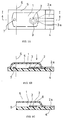
- Figure 1A is a plan view showing an example of the first sensor before use.
- Figure 1B is a cross-sectional view of the first sensor taken along line I-I of Figure 1A.
- Figure 1C is a cross-sectional view showing an example of the first sensor in use.
- the same parts bear the same reference numerals.
- the first sensor is an electrochemical sensor. More specifically, an active electrode 2 and a counter electrode 3 are arranged substantially in the center of a rectangular substrate 4. A reagent (not shown) that causes an electrochemical change upon reaction with a sample is arranged on the electrodes 2 and 3. This part constitutes an analyzing part. The ends of the active electrode 2 and the counter electrode 3 extend toward one end of the substrate 4 (the right end in Figure 1A) so as to constitute an active electrode terminal 2a and a counter electrode terminal 3a. The entire surface except the terminals 2a and 3a is covered with a cover film 5.
- the edge of the cover film 5 is tightly attached to the substrate 4, but a gap is formed between the cover film 5 and the substrate 4 in the portion other than the edge of the cover film 5.
- This gap constitutes a capillary passage 1.
- the active electrode 2 and the counter electrode 3 are positioned in one end of the capillary passage 1 (the right end in Figure 1A).
- a desiccant 7 may be arranged in the other end of the capillary passage 1 (the left end in Figure 1A). The desiccant 7 can prevent the deterioration of the electrodes or the reagent.
- the sensor is cut along the dashed line 6, and an air vent 8 is opened at the position shown by the arrow in Figure 1B.
- the parts other than the electrodes are formed of an insulating material.
- the substrate 4 can be formed of polyethylene terephthalate (PET), acrylonitrile-butadiene-styrene copolymer (ABS resin), polystyrene, nonyl, polyethylene, acrylic resin, vinylidene chloride resin or the like.
- PET polyethylene terephthalate
- ABS resin acrylonitrile-butadiene-styrene copolymer
- polystyrene nonyl
- polyethylene acrylic resin
- vinylidene chloride resin vinylidene chloride resin
- the above-listed materials and other materials such as paper may be laminated so as to form the substrate 4.
- the cover film can be formed of a material as listed as the material for the substrate 4. Examples of the material for the cover film include PET, polyethylene, polyvinyl chloride or the like.
- spacers may be placed between the substrate and the cover film, as described in Japanese Patent Publication No. 6-58338
- the electrodes 2 and 3 and the terminals thereof 2a and 3a can be formed of precious metal such as gold, silver and platinum, carbon or the like.
- the sensor of the present invention can be produced in the following manner. First, the terminals 2a and 3a are screen printed on the substrate by using silver paste. The active electrode 2 and the counter electrode 3 are screen printed with conductive carbon paste. The shapes of the active electrode and the counter electrode are not limited to the shapes shown in Figure 1A.
- the cover film 5 formed into a predetermined shape is placed on the substrate 4. Then, the edge of the cover film is attached to the substrate 4. Thus, the sensor shown in Figure 1A can be produced. The attachment can be performed by using an adhesive or by pressing while heating (laminating). In the case of a sensor that electrically detects an electrochemical reaction between a sample and a reagent, the reagent is generally placed on the active electrode 2 and the counter electrode 3.
- a separately prepared reagent film may be used to be placed on the electrodes 2 and 3.
- a reagent layer may be formed directly on the electrodes 2 and 3.
- a hydrophilic polymer aqueous solution may be applied onto the electrodes 2 and 3 and then dried. Then, a reagent solution may be applied thereto and dried. Thus, a reagent layer can be formed.
- a carboxymethyl-cellulose (CMC) aqueous solution can be used for the hydrophilic polymer aqueous solution.
- the reagent for example, in the analysis of lactic acid, an aqueous solution of lactic acid oxidase and potassium ferricyanide can be used.
- glucose oxidase can be used, instead of lactic acid oxidase.
- cholesterol oxidase can be used, instead of lactic acid oxidase.
- gold or platinum electrodes can be used for measurement of an amount of hydrogen peroxide decreased or an amount of oxygen decreased in the detection of the results of the enzyme reaction.
- a reaction is detected by a mediator
- potassium ferricyanide, ferrocene or the like can be used as the mediator.
- the size of the sensor before use shown in Figure 1A is not particularly limited. Generally, the entire size is 3 to 50mm in length, 3 to 10mm in width, 0.2 to 2mm in the maximum thickness, and 0.1 to 0.5mm in the minimum thickness. The volume is about 0.5 to 10 ⁇ l.
- the sensor is provided with an opening 9 to let in a sample by cutting the sensor at the position shown by the dashed line 6 of Figure 1A.
- the sensor can be cut with an ordinary cutting tool such as scissors or a cutter.
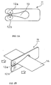
- a cutter shown in Figures 2A and 2B which is dedicated to serve this purpose, is preferably used.
- the cutter 11 includes a pair of round blades 12a and 12b and a space 13 in which the sensor is inserted.
- the sensor 14 is inserted into the space 13 to be positioned in a cutting location, then moved in the direction shown by the arrow. Then, the round blades 12a and 12b cut the sensor 14.
- the cutting position is not particularly limited, as long as an opening for letting in a sample can be provided in the sensor. However, it is preferable to cut the sensor in a position that allows a capillary passage to have a suitable length when a capillary passage is formed. This is because an excessively short capillary passage prevents the expression of the capillary phenomenon. Furthermore, it is preferable to form an air vent 8 at the time of this cutting.
- the cover film is formed of resin
- the air vent 8 can be formed by piercing the cover film with a needle or the like. It is preferable to heat the needle before piercing. The heated needle can easily form the air vent 8 simply by being contacted with the cover film, and this method of forming the air vent 8 hardly causes a change in the volume of the analyzing part or the passage.
- the thus produced sensor provided with the sample inlet 9 can be used in the same manner as an ordinary sensor.
- a sample such as blood is contacted with the sample inlet 9, the capillary phenomenon allows the sample to be introduced into the analyzing part where the electrodes 2 and 3 are positioned. Then, the sensor is positioned in a measuring device so that predetermined test items are measured.
- an electrochemical sensor has been described.
- the electrodes for the analyzing part in the electrochemical sensor are replaced by a reagent that effects an optical change upon reaction with a sample.
- the configuration and the material for the optical sensor are the same as those of the electrochemical sensor, for example, except that the portion of the sensor that is irradiated with light (which is transmissive, if necessary) is transparent.
- the reagent that effects an optical change upon reaction with a sample can be suitably selected in accordance with the test item. Examples of such a reagent include a reagent obtained by combining a color-developing substrate and peroxidase (POD).
- the reagent can be placed on the analyzing part in the same manner as in the case of the electrochemical sensor.
- PET, an acrylic resin or the like can be used as a transparent material for the substrate and the cover film.
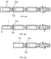
- Figures 3A to 3C are plan views showing a set of sensors, each of which is as shown in Figures 1A to 1C.
- Figures 3A to 3C the same parts as in Figures 1A to 1C bear the same reference numerals.
- Figure 3A shows a set of sensors before use. As shown in Figure 3A, the set of sensors is formed by aligning the sensors of Figure 1A in the longitudinal direction so that the sensors are integrated, and the substrate is continuous.
- the arrow in Figure 3A shows a position at which the sensor is cut so as to form an inlet for a sample. This set of sensors is generally positioned in a measuring device.
- Japanese Laid-Open Patent Publication No. 7-167820 discloses an example of the measuring device including the cutter therein, which can be used in the present invention. Furthermore, the electrode terminals 2a and 3a are exposed so as to be connected to the terminals of the measuring device.
- the electrodes of an individual sensor may be independent from each other. Alternatively, the electrodes and the terminals may be integrated, and the electrodes are continuously linear and shared by a plurality of sensors, as in the sensor disclosed in Japanese Laid-Open Patent Publication No. 7-167820. This is advantageous in the production.
- the length of the sensor is suitably determined by the number of the sensors that are to be arranged.
- the sizes other than the length are the same as those of the sensor of Figure 1A.
- This set of sensors can be produced by forming a plurality pairs of electrodes on one belt-shaped substrate and attaching a cover film for each sensor in the same manner as described above.
- This set of sensors is used, for example in the following manner.
- the set of sensors shown in Figure 3A is positioned in a measuring device.
- a sensor is cut at the position shown by the arrow in Figure 3A with a cutter provided in the measuring device or the like, so that a sample inlet is formed, as shown in Figure 3B.
- a sample such as blood is introduced from the sample inlet to the analyzing part so as to measure the sample, as described above.
- the sensor is cut off at the position shown by the arrow in Figure 3B so as to obtain a set of sensors shown in Figure 3C.
- the set of sensors shown in Figure 3C is provided with no opening so that the capillary passage and the analyzing part are sealed from the outside.
- another sensor is cut in the same position as that shown by the arrow in Figure 3A, so that the sensor is provided with a sample inlet.
- a set of optical sensors has the same configuration as that of the electrochemical sensor, except that a predetermined reagent is arranged instead of the electrodes, and a predetermined portion can be observed from outside by making the portion transparent or the like.
- Figure 4A is a plan view showing a sensor before use
- Figure 4B is a cross-sectional view of the sensor taken along line II-II of Figure 4A
- Figure 5A is a plan view showing a sensor in use
- Figure 5B is a cross-sectional view of the sensor taken along line III-III of Figure 5A.
- the sensor shown in these figures is obtained by partially covering the sensor in use of Example 1 (see Figure 1C) with a cap.
- a cap 10 covers the sample inlet 9 and the air vent 8 of the sensor before use so that the capillary passage 1 and the analyzing part (where the electrodes 2 and 3 are positioned) are sealed from the outside. Furthermore, a desiccant 7 may be placed at an inner part of the cap 10.
- the shape, size and material of the sensor are not particularly limited, as long as the cap 10 can seal the sample inlet 9 and the air vent 8.
- the inner shape of the cap shown in Figures 4A and 4B is substantially a hexahedron.
- the size of the cap is suitably determined by the size of the sensor.
- the minimum size of the inner shape is generally about 1.5mm in depth, about 3mm in width and about 0.2mm in height.
- the cap can be formed of any resin that is listed above as a material for the substrate or the cover film. Among them, chlorinated polyethylene, butadiene resin or the like, which have elasticity, are preferable.
- the configuration, size, material or the like of the sensor except for the provision of the cap are the same as those of the sensor in Example 1.
- the relationship between the electrochemical sensor and an optical sensor configured according to Example 2 is the same as that in Example 1.
- a method for producing the sensor of Example 2 is the same as that of Example 1, except that the sample inlet 9 and the air vent 8 are formed beforehand.
- the cap is provided in the sensor in Example 2 before use.
- the cap is removed, as shown in Figures 5A and 5B. Thereafter, the sensor can be used in the same manner as in Example 1.
- Figures 6A to 6C are plan views showing a set of the sensors, each one of which is as shown in Figures 4A, 4B and 5A and 5B.
- the same parts bear the same reference numerals.
- the cap 10 in the set of the sensors, the cap 10 has two recesses. One of the recesses is deep so that the portion on the side of the sample inlet of the sensor is inserted and engaged therein. The other recess is shallow so that the portion on the side of the terminals 2a and 3a of the sensor is inserted and engaged therein.
- the sensors are arranged in a line in the longitudinal direction via the caps so as to be integrated.
- This set of sensors is generally positioned in a measuring device for use.
- the length of the set of sensors is suitably determined by the number of the sensors that are to be arranged, and other sizes are the same as those of the sensor shown in Figures 4A, 4B and 5A, 5B.
- This set of sensors can be used, for example in the following manner. First, the set of sensors shown in Figure 6A is positioned in a measuring device. Then, the cap 10 is removed for use while the sample inlet portion at one end of the sensor protrudes from the measuring device, so that the sample inlet is exposed, as shown in Figure 6B. Then, as described above, a sample such as blood is introduced from the sample inlet to the analyzing part for measurement. After the measurement, the used sensor is removed from a next cap so as to obtain the sensors shown in Figure 6C.
- This set of sensors which is provided with no sample inlets nor air vents, has the same state as an unused sensor so that the capillary passage and the analyzing part are sealed from the outside. When a next test is to be carried out, the cap of a next sensor is removed so as to provide a sample inlet again.
- the use of the set of sensors of the present invention facilitates the replacement of the sensors so that the operability can be improved.
- a set of optical sensors has the same configuration as that of the electrochemical sensor, except that a predetermined reagent is arranged, instead of the electrodes, and that a predetermined portion can be observed from outside by making the portion transparent or the like.
Landscapes
- Chemical & Material Sciences (AREA)
- Health & Medical Sciences (AREA)
- Clinical Laboratory Science (AREA)
- Analytical Chemistry (AREA)
- General Health & Medical Sciences (AREA)
- Hematology (AREA)
- Dispersion Chemistry (AREA)
- Chemical Kinetics & Catalysis (AREA)
- Investigating Or Analysing Biological Materials (AREA)
- Investigating Or Analysing Materials By The Use Of Chemical Reactions (AREA)
- Sampling And Sample Adjustment (AREA)
- Harvester Elements (AREA)
- Measuring Pulse, Heart Rate, Blood Pressure Or Blood Flow (AREA)
- Optical Measuring Cells (AREA)
- Automatic Analysis And Handling Materials Therefor (AREA)
Abstract
Description
- The present invention relates to a sensor and a set of sensors for use, for example, in measurement of a liquid sample of an organism.
- Conventionally, a disposable sensor has been used for general purposes in the field of clinical tests such as biochemical analysis (e.g., Japanese Laid-Open Patent Publication No. 4-188065 and Japanese Patent Publication No. 6-58338). A disposable sensor does not need cleaning after measurement, so that it is suitable for personal use. In particular, a sensor having a capillary passage easily used with a liquid sample such as blood is advantageous for self-monitoring such as self-measurement of blood glucose. Such a sensor can be categorized into two types, i.e., electrochemical type and optical type, which are different from each other in the detecting means.
- An electrochemical sensor is provided with, for example, electrodes arranged on a rectangular substrate and a passage through which a sample flows. An end of the passage constitutes an inlet for a sample. A reagent that is changed electrochemically when it reacts with the sample is generally placed on the electrodes. When a sample such as blood is contacted with the sample inlet, the sample is drawn through the passage into an electrode part (analyzing part) by capillary phenomenon, and the sample reacts with the reagent. A component of the sample can be analyzed in the following manner. This sensor is positioned in a measuring device, a sample is supplied, and a voltage is applied to the electrodes. Then, a reaction with the reagent is detected by the electrodes as an electrochemical change.
- In an optical sensor, instead of the electrodes and the reagent that effects an electrochemical change, a reagent that effects an optical change when it reacts with a sample is placed on the substrate. A part of the sensor is externally observable by being transparent so that the optical change is detected outside the sensor. Other than that, the optical sensor has the same configuration as that of the electrochemical sensor. The optical change of the reagent is measured by visual observation, a spectrophotometer, a reflectometer or the like. In this manner, a component of the sample is analyzed.
- High precision in measurement is required for such a sensor. Therefore, the sensor is prevented from being in contact with the outside, for example, by being contained in a can or closely packaged with an aluminum foil seal one by one, in order to ensure temporal stability of a reagent containing enzyme or to prevent a substance that could interfere with measurement from entering the sensor. However, the containment in a can or the packaging with seals increases the number of steps for production of the sensor, thus leading to high cost. In addition, the containment or the packaging makes the sensor more difficult to use.
- Therefore, with the foregoing in mind, it is the object of the present invention to provide a sensor or a set of sensors that are protected against a substance that could interfere with measurement or could deteriorate the sensors, have temporal stability, permit high production efficiency, and have excellent operability.
- In order to achieve the above object, the present invention provides a first sensor and a second sensor described as follows.
- A first sensor of the present invention includes an analyzing part and a passage having two ends. One end of the passage is connected to the analyzing part. The other end of the passage is closed before use so that the inside of the passage and the analyzing part are sealed to prevent contact with the outside. When the sensor is to be used, the other end of the passage may be opened so as to provide an inlet for a sample.
- Thus, the first sensor of the present invention has no inlet for a sample before use, so that the inside of the passage and the analyzing part are sealed to prevent contact with the outside. In the sensor in this embodiment, a substance that could interfere with measurement is prevented from entering the sensor, thereby resulting in excellent temporal stability of the electrodes or the reagent. In addition, the sensor of the present invention can be produced in a more simplified step than the step of packaging the sensors individually. Moreover, in use, when the end of the sensor where the end of the passage is positioned is cut off by a cutter or the like, the end of the passage can be opened easily so that the opening can serve as an inlet for a sample. The provision of the opening can be performed in a manner as simple as the conventional operation of opening the individual package of the sensor. When a cutter dedicated for this purpose is used, the opening can be provided more efficiently.
- In one embodiment of the first sensor of the present invention, the passage is preferably a capillary passage, and an air vent in communication with the capillary passage is preferably formed when the sensor is to be used. When the passage is a capillary passage, the formation of an air vent strengthens the suction by the capillary phenomenon. Even if there is no air vent, a strong capillary phenomenon can occur in the passage, if there is a place such as an air reservoir to which the air in the capillary passage can escape.
- The first sensors of the present invention are preferably used as a set where a plurality of sensors are integrated into one unit. The use of such a set of sensors improves the efficiency in replacement of the sensors.
- A second sensor of the present invention includes a passage having two ends, an analyzing part and an inlet for a sample. One end of the passage is connected to the analyzing part. The other end of the passage constitutes the inlet for a sample. The inlet for a sample is closed with a sealing member before use so that the inside of the passage and the analyzing part are sealed to prevent contact with the outside. When the sensor is to be used, the sealing member is removed so as to expose the inlet for a sample.
- Thus, in the second sensor of the present invention, the inlet for a sample is closed with a sealing member before use so that the inside of the passage and the analyzing part are sealed to prevent contact with the outside. In the sensor in this embodiment, a substance that could interfere with measurement or could deteriorate the sensors is prevented from entering the sensor, thus resulting in excellent temporal stability of the electrodes or the reagent. In addition, the sensor of the present invention can be produced in more simplified steps than the production steps including the step of packaging the sensors individually. Moreover, in use, the sealing member may be removed so that the inlet for a sample can be exposed. The provision of the opening can be performed in a manner as simple as the conventional operation of opening the individual package of the sensor.
- In the second sensor of the present invention, the passage is preferably a capillary passage for the same reason as described with reference to the first sensor. The second sensor preferably includes an air vent in communication with the capillary passage. The air vent is preferably closed with a sealing member before use. When the sensor is to be used, the sealing member is preferably removed so as to expose the air vent.
- The second sensors of the present invention are preferably used as a set where a plurality of sensors are integrated into one unit for the same reason as described with reference to the first sensor.
- In the first and the second sensors, in the case of electrochemical sensors, at least an active electrode and a counter electrode are generally arranged in the analyzing part. In the case of optical sensors, a reagent that effects an optical change when reacting with a sample is arranged in the analyzing part.
- As described above, in these embodiments of the sensor and the set of the sensors of the present invention, the passage and the analyzing part are sealed from the outside. Therefore, without packaging the sensors individually, a substance that could interfere with measurement can be prevented from entering the sensors, thus resulting in excellent temporal stability of the electrodes or the reagent. In addition, the operability of the sensor can be improved. Moreover, the sensor in these embodiments can be produced in a simplified manner. In addition, the step of packaging the sensors individually can be eliminated, so that the production efficiency can be higher than that of conventional sensors.
- These and other advantages of the present invention will become apparent to those skilled in the art upon reading and understanding the following detailed description with reference to the accompanying figures.
- Figure 1A is a plan view showing an example of a sensor of the present invention.
- Figures 1B and 1C are cross-sectional views showing the sensor shown in Figure 1A.
- Figure 2A is a plan view showing an example of a cutter for cutting the sensor of the present invention.
- Figure 2B is a perspective view showing an example where the cutter of Figure 2A is cutting the sensor.
- Figures 3A to 3C are plan views showing an example of a set of sensors of the present invention.
- Figure 4A is a plan view showing another example of a sensor of the present invention before use.
- Figure 4B is a cross-sectional view showing the sensor shown in Figure 4A.
- Figure 5A is a plan view showing the sensor of Figure 4A in use.
- Figure 5B is a cross-sectional view showing the sensor shown in Figure 5A.
- Figures 6A to 6C are plan views showing a set of the sensors of Figure 4A of the present invention.
-
- Hereinafter, the sensor of the present invention will be described by way of examples with reference to the accompanying drawings.
- Figures 1A through 1C show an example of a first sensor of the present invention. Figure 1A is a plan view showing an example of the first sensor before use. Figure 1B is a cross-sectional view of the first sensor taken along line I-I of Figure 1A. Figure 1C is a cross-sectional view showing an example of the first sensor in use. In Figures 1A through 1C, the same parts bear the same reference numerals.
- As shown in Figures 1A and 1B, the first sensor is an electrochemical sensor. More specifically, an
active electrode 2 and acounter electrode 3 are arranged substantially in the center of arectangular substrate 4. A reagent (not shown) that causes an electrochemical change upon reaction with a sample is arranged on theelectrodes active electrode 2 and thecounter electrode 3 extend toward one end of the substrate 4 (the right end in Figure 1A) so as to constitute anactive electrode terminal 2a and a counter electrode terminal 3a. The entire surface except theterminals 2a and 3a is covered with acover film 5. The edge of thecover film 5 is tightly attached to thesubstrate 4, but a gap is formed between thecover film 5 and thesubstrate 4 in the portion other than the edge of thecover film 5. This gap constitutes acapillary passage 1. Theactive electrode 2 and thecounter electrode 3 are positioned in one end of the capillary passage 1 (the right end in Figure 1A). A desiccant 7 may be arranged in the other end of the capillary passage 1 (the left end in Figure 1A). The desiccant 7 can prevent the deterioration of the electrodes or the reagent. In Figures 1A and 1B, the sensor is cut along the dashedline 6, and anair vent 8 is opened at the position shown by the arrow in Figure 1B. - In this sensor, which is an electrochemical sensor, the parts other than the electrodes are formed of an insulating material. For example, the
substrate 4 can be formed of polyethylene terephthalate (PET), acrylonitrile-butadiene-styrene copolymer (ABS resin), polystyrene, nonyl, polyethylene, acrylic resin, vinylidene chloride resin or the like. Alternatively, the above-listed materials and other materials such as paper may be laminated so as to form thesubstrate 4. The cover film can be formed of a material as listed as the material for thesubstrate 4. Examples of the material for the cover film include PET, polyethylene, polyvinyl chloride or the like. In the sensor of the present invention, spacers may be placed between the substrate and the cover film, as described in Japanese Patent Publication No. 6-58338. - The
electrodes terminals thereof 2a and 3a can be formed of precious metal such as gold, silver and platinum, carbon or the like. - The sensor of the present invention can be produced in the following manner. First, the
terminals 2a and 3a are screen printed on the substrate by using silver paste. Theactive electrode 2 and thecounter electrode 3 are screen printed with conductive carbon paste. The shapes of the active electrode and the counter electrode are not limited to the shapes shown in Figure 1A. Thecover film 5 formed into a predetermined shape is placed on thesubstrate 4. Then, the edge of the cover film is attached to thesubstrate 4. Thus, the sensor shown in Figure 1A can be produced. The attachment can be performed by using an adhesive or by pressing while heating (laminating). In the case of a sensor that electrically detects an electrochemical reaction between a sample and a reagent, the reagent is generally placed on theactive electrode 2 and thecounter electrode 3. A separately prepared reagent film may be used to be placed on theelectrodes electrodes electrodes - For example, gold or platinum electrodes can be used for measurement of an amount of hydrogen peroxide decreased or an amount of oxygen decreased in the detection of the results of the enzyme reaction. In a method in which a reaction is detected by a mediator, potassium ferricyanide, ferrocene or the like can be used as the mediator.
- The size of the sensor before use shown in Figure 1A is not particularly limited. Generally, the entire size is 3 to 50mm in length, 3 to 10mm in width, 0.2 to 2mm in the maximum thickness, and 0.1 to 0.5mm in the minimum thickness. The volume is about 0.5 to 10µl.
- Next, as shown in Figure 1C, the sensor is provided with an
opening 9 to let in a sample by cutting the sensor at the position shown by the dashedline 6 of Figure 1A. The sensor can be cut with an ordinary cutting tool such as scissors or a cutter. However, a cutter shown in Figures 2A and 2B, which is dedicated to serve this purpose, is preferably used. As shown in the plan view of Figure 2A, thecutter 11 includes a pair ofround blades space 13 in which the sensor is inserted. As shown in Figure 2B, thesensor 14 is inserted into thespace 13 to be positioned in a cutting location, then moved in the direction shown by the arrow. Then, theround blades sensor 14. The cutting position is not particularly limited, as long as an opening for letting in a sample can be provided in the sensor. However, it is preferable to cut the sensor in a position that allows a capillary passage to have a suitable length when a capillary passage is formed. This is because an excessively short capillary passage prevents the expression of the capillary phenomenon. Furthermore, it is preferable to form anair vent 8 at the time of this cutting. When the cover film is formed of resin, theair vent 8 can be formed by piercing the cover film with a needle or the like. It is preferable to heat the needle before piercing. The heated needle can easily form theair vent 8 simply by being contacted with the cover film, and this method of forming theair vent 8 hardly causes a change in the volume of the analyzing part or the passage. - The thus produced sensor provided with the
sample inlet 9 can be used in the same manner as an ordinary sensor. For example, a sample such as blood is contacted with thesample inlet 9, the capillary phenomenon allows the sample to be introduced into the analyzing part where theelectrodes - In this example, an electrochemical sensor has been described. In an optical sensor, the electrodes for the analyzing part in the electrochemical sensor are replaced by a reagent that effects an optical change upon reaction with a sample. The configuration and the material for the optical sensor are the same as those of the electrochemical sensor, for example, except that the portion of the sensor that is irradiated with light (which is transmissive, if necessary) is transparent. The reagent that effects an optical change upon reaction with a sample can be suitably selected in accordance with the test item. Examples of such a reagent include a reagent obtained by combining a color-developing substrate and peroxidase (POD). The reagent can be placed on the analyzing part in the same manner as in the case of the electrochemical sensor. Furthermore, PET, an acrylic resin or the like can be used as a transparent material for the substrate and the cover film.
- Next, Figures 3A to 3C are plan views showing a set of sensors, each of which is as shown in Figures 1A to 1C. In Figures 3A to 3C, the same parts as in Figures 1A to 1C bear the same reference numerals. Figure 3A shows a set of sensors before use. As shown in Figure 3A, the set of sensors is formed by aligning the sensors of Figure 1A in the longitudinal direction so that the sensors are integrated, and the substrate is continuous. The arrow in Figure 3A shows a position at which the sensor is cut so as to form an inlet for a sample. This set of sensors is generally positioned in a measuring device. Every time a test is carried out, the sensor is cut with a cutter provided in the measuring device so as to form a sample inlet, and the used sensor is disposed of. Japanese Laid-Open Patent Publication No. 7-167820 discloses an example of the measuring device including the cutter therein, which can be used in the present invention. Furthermore, the
electrode terminals 2a and 3a are exposed so as to be connected to the terminals of the measuring device. The electrodes of an individual sensor may be independent from each other. Alternatively, the electrodes and the terminals may be integrated, and the electrodes are continuously linear and shared by a plurality of sensors, as in the sensor disclosed in Japanese Laid-Open Patent Publication No. 7-167820. This is advantageous in the production. - The length of the sensor is suitably determined by the number of the sensors that are to be arranged. The sizes other than the length are the same as those of the sensor of Figure 1A. This set of sensors can be produced by forming a plurality pairs of electrodes on one belt-shaped substrate and attaching a cover film for each sensor in the same manner as described above.
- This set of sensors is used, for example in the following manner. First, the set of sensors shown in Figure 3A is positioned in a measuring device. In use, a sensor is cut at the position shown by the arrow in Figure 3A with a cutter provided in the measuring device or the like, so that a sample inlet is formed, as shown in Figure 3B. Then, a sample such as blood is introduced from the sample inlet to the analyzing part so as to measure the sample, as described above. After measurement, the sensor is cut off at the position shown by the arrow in Figure 3B so as to obtain a set of sensors shown in Figure 3C. The set of sensors shown in Figure 3C is provided with no opening so that the capillary passage and the analyzing part are sealed from the outside. Then, when a next test is carried out, another sensor is cut in the same position as that shown by the arrow in Figure 3A, so that the sensor is provided with a sample inlet.
- The use of such a set of the sensors of the present invention facilitates the replacement of the sensors so that measurement operations are simplified. In addition, a large number of samples are treated quickly and easily.
- A set of optical sensors has the same configuration as that of the electrochemical sensor, except that a predetermined reagent is arranged instead of the electrodes, and a predetermined portion can be observed from outside by making the portion transparent or the like.
- Next, a second sensor of the present invention will be described with reference to Figures 4A, 4B and 5A, 5B. Figure 4A is a plan view showing a sensor before use, and Figure 4B is a cross-sectional view of the sensor taken along line II-II of Figure 4A. Figure 5A is a plan view showing a sensor in use, and Figure 5B is a cross-sectional view of the sensor taken along line III-III of Figure 5A. In these figures, the same parts bear the same reference numerals. The sensor shown in these figures is obtained by partially covering the sensor in use of Example 1 (see Figure 1C) with a cap.
- More specifically, as shown in Figures 4A, a
cap 10 covers thesample inlet 9 and theair vent 8 of the sensor before use so that thecapillary passage 1 and the analyzing part (where theelectrodes cap 10. - The shape, size and material of the sensor are not particularly limited, as long as the
cap 10 can seal thesample inlet 9 and theair vent 8. For example, the inner shape of the cap shown in Figures 4A and 4B is substantially a hexahedron. The size of the cap is suitably determined by the size of the sensor. The minimum size of the inner shape is generally about 1.5mm in depth, about 3mm in width and about 0.2mm in height. Furthermore, the cap can be formed of any resin that is listed above as a material for the substrate or the cover film. Among them, chlorinated polyethylene, butadiene resin or the like, which have elasticity, are preferable. - The configuration, size, material or the like of the sensor except for the provision of the cap are the same as those of the sensor in Example 1. The relationship between the electrochemical sensor and an optical sensor configured according to Example 2 is the same as that in Example 1. A method for producing the sensor of Example 2 is the same as that of Example 1, except that the
sample inlet 9 and theair vent 8 are formed beforehand. - The cap is provided in the sensor in Example 2 before use. When the sensor is to be used, the cap is removed, as shown in Figures 5A and 5B. Thereafter, the sensor can be used in the same manner as in Example 1.
- Figures 6A to 6C are plan views showing a set of the sensors, each one of which is as shown in Figures 4A, 4B and 5A and 5B. In these figures, the same parts bear the same reference numerals. As shown in Figure 6A, in the set of the sensors, the
cap 10 has two recesses. One of the recesses is deep so that the portion on the side of the sample inlet of the sensor is inserted and engaged therein. The other recess is shallow so that the portion on the side of theterminals 2a and 3a of the sensor is inserted and engaged therein. Thus, the sensors are arranged in a line in the longitudinal direction via the caps so as to be integrated. This set of sensors is generally positioned in a measuring device for use. - The length of the set of sensors is suitably determined by the number of the sensors that are to be arranged, and other sizes are the same as those of the sensor shown in Figures 4A, 4B and 5A, 5B.
- This set of sensors can be used, for example in the following manner. First, the set of sensors shown in Figure 6A is positioned in a measuring device. Then, the
cap 10 is removed for use while the sample inlet portion at one end of the sensor protrudes from the measuring device, so that the sample inlet is exposed, as shown in Figure 6B. Then, as described above, a sample such as blood is introduced from the sample inlet to the analyzing part for measurement. After the measurement, the used sensor is removed from a next cap so as to obtain the sensors shown in Figure 6C. This set of sensors, which is provided with no sample inlets nor air vents, has the same state as an unused sensor so that the capillary passage and the analyzing part are sealed from the outside. When a next test is to be carried out, the cap of a next sensor is removed so as to provide a sample inlet again. - The use of the set of sensors of the present invention facilitates the replacement of the sensors so that the operability can be improved.
- As described in Example 1, a set of optical sensors has the same configuration as that of the electrochemical sensor, except that a predetermined reagent is arranged, instead of the electrodes, and that a predetermined portion can be observed from outside by making the portion transparent or the like.
Claims (12)
- A sensor comprising an analyzing part and a passage (1) having two ends, one end of the passage (1) being connected to the analyzing part,
wherein the other end of the passage (1) is closed before use so that an inside of the passage and the analyzing part are sealed to prevent contact with the outside, andsaid other end of the passage (1) being openable so as to provide an inlet (9) for the sample when the sensor is to be used. - The sensor according to claim 1, wherein the passage (1) is a capillary passage, and having an air vent (8) in communication with the capillary passage when the sensor is to be used.
- A sensor comprising a passage (1) having two ends, an analyzing part (2, 3) and an inlet (9) for a sample, one end of the passage (1) being connected to the analyzing part, the other end of the passage (1) constituting the inlet (9) for a sample,
wherein the inlet (9) for a sample is closed with a sealing member (10) before use so that an inside of the passage (1) and the analyzing part are sealed to prevent contact with the outside, andthe sealing member (10) being removable so as to expose the inlet (9) for a sample when the sensor is to be used. - The sensor according to claim 3,
wherein the passage (1) is a capillary passage,the sensor includes an air vent (8) in communication with the capillary passage,the air vent (8) is closed with a sealing member (10) before use, andthe sealing member (10) being removable so as to expose the air vent (8) when the sensor is to be used. - The sensor according to any of claims 1 to 4, wherein at least an active electrode (2) and a counter electrode (3) are arranged in the analyzing part.
- The sensor according to any of claims 1 to 4, wherein a reagent that effects an optical change when reacting with a sample is arranged in the analyzing part.
- A set of sensors, wherein a plurality of sensors according to any of claims 1 to 6 integrated into one unit.
- The set of sensors according to claim 7 as dependent on claim 1 or claim 2, wherein the plurality of sensors are formed on one substrate (4).
- The set of sensors of claim 7 as dependent on claim 3 or claim 4,
wherein the sealing member (10 has two recesses,a side of the inlet (9) for a sample of the sensor being inserted and engaged in one of the recesses, andthe side opposite to the inlet for a sample being inserted and engaged in the other recess, whereby a plurality of sensors are connected via the sealing members (10). - A method of analyzing a sample fluid, comprising:providing a sensor comprising an analyzing part and a passage (1) having two ends, one end of the passage (1) being connected to the analyzing part, wherein the other end of the passage (1) is closed before use so that an inside of the passage and the analyzing part are sealed to prevent contact with the outside,opening the other end of the passage to provide an inlet (9) for a sample, andcontacting the inlet (9) with the sample fluid to draw the fluid to the analyzing part.
- The method of claim 10, wherein the passage (1) is a capillary passage and the method further comprises forming an air vent (8) in communication with the capillary passage when the sensor is to be used.
- A method of analyzing a sample fluid, comprising:providing a sensor comprising a passage (1) having two ends, an analyzing part and an inlet (9) for a sample, one end of the passage (1) being connected to the analyzing part, the other end of the passage (1) constituting the inlet (9) for a sample, wherein the inlet (9) for a sample is closed with a sealing member (10) before use so that an inside of the passage (1) and the analyzing part are sealed to prevent contact with the outside,removing the sealing member (10) so as to expose the inlet (9) for a sample when the sensor is to be used, andcontacting the inlet (9) with the sample fluid to draw the fluid to the analyzing part.
Applications Claiming Priority (2)
| Application Number | Priority Date | Filing Date | Title |
|---|---|---|---|
| JP34832097 | 1997-12-17 | ||
| JP34832097A JP3896435B2 (en) | 1997-12-17 | 1997-12-17 | Sensor and sensor assembly |
Publications (3)
| Publication Number | Publication Date |
|---|---|
| EP0924520A2 true EP0924520A2 (en) | 1999-06-23 |
| EP0924520A3 EP0924520A3 (en) | 2001-04-04 |
| EP0924520B1 EP0924520B1 (en) | 2005-08-31 |
Family
ID=18396246
Family Applications (1)
| Application Number | Title | Priority Date | Filing Date |
|---|---|---|---|
| EP98310317A Expired - Lifetime EP0924520B1 (en) | 1997-12-17 | 1998-12-16 | A set of sensors |
Country Status (5)
| Country | Link |
|---|---|
| US (1) | US6125292A (en) |
| EP (1) | EP0924520B1 (en) |
| JP (1) | JP3896435B2 (en) |
| AT (1) | ATE303596T1 (en) |
| DE (1) | DE69831384T2 (en) |
Cited By (6)
| Publication number | Priority date | Publication date | Assignee | Title |
|---|---|---|---|---|
| EP1413880A1 (en) * | 2001-07-27 | 2004-04-28 | Arkray, Inc. | Analyzing instrument |
| WO2006005483A1 (en) * | 2004-07-09 | 2006-01-19 | Roche Diagnostics Gmbh | Analytical test element |
| EP2407775A1 (en) * | 2010-07-12 | 2012-01-18 | Arkray, Inc. | Biosensor and biosensor manufacturing method |
| US9017544B2 (en) | 2002-10-04 | 2015-04-28 | Roche Diagnostics Operations, Inc. | Determining blood glucose in a small volume sample receiving cavity and in a short time period |
| US9017543B2 (en) | 2001-11-16 | 2015-04-28 | Roche Diagnostics Operations, Inc. | Method for determining the concentration of an analyte in a liquid sample using small volume samples and fast test times |
| US10041901B2 (en) | 2013-03-15 | 2018-08-07 | Roche Diabetes Care, Inc. | Electrode configuration for a biosensor |
Families Citing this family (22)
| Publication number | Priority date | Publication date | Assignee | Title |
|---|---|---|---|---|
| JP2003529061A (en) * | 2000-03-28 | 2003-09-30 | ダイアビ−ティ−ズ・ダイアグノスティックス・インコ−ポレイテッド | Continuous manufacturing method of disposable electrochemical sensor |
| EP1167538A1 (en) * | 2000-06-30 | 2002-01-02 | Schibli Engineering GmbH | Biosensor and method for its production |
| US6488828B1 (en) * | 2000-07-20 | 2002-12-03 | Roche Diagnostics Corporation | Recloseable biosensor |
| HUP0302819A2 (en) * | 2000-08-29 | 2003-12-29 | Nestle Sa | Flexible container having flat walls |
| US6814843B1 (en) * | 2000-11-01 | 2004-11-09 | Roche Diagnostics Corporation | Biosensor |
| US6558528B1 (en) * | 2000-12-20 | 2003-05-06 | Lifescan, Inc. | Electrochemical test strip cards that include an integral dessicant |
| GB0128350D0 (en) * | 2001-11-27 | 2002-01-16 | Lab901 Ltd | Non-rigid apparatus for microfluidic applications |
| US8460523B2 (en) * | 2002-12-02 | 2013-06-11 | Arkray, Inc. | Analysis instrument |
| US20050247573A1 (en) * | 2004-03-23 | 2005-11-10 | Hideaki Nakamura | Biosensors |
| DE102004050062A1 (en) * | 2004-10-13 | 2006-04-27 | Boehringer Ingelheim Microparts Gmbh | Apparatus, meter and method for receiving and assaying or manipulating sample fluids in a microfluidic platform |
| US8691161B2 (en) * | 2004-12-13 | 2014-04-08 | Bayer Healthcare Llc | Self-contained test sensor |
| KR101017279B1 (en) * | 2006-11-06 | 2011-02-28 | 아크레이 가부시키가이샤 | Cartridge and analysis system |
| JP4852399B2 (en) * | 2006-11-22 | 2012-01-11 | 富士フイルム株式会社 | Two-component merger |
| US20100051455A1 (en) * | 2008-08-26 | 2010-03-04 | Roche Diagnostics Operations, Inc. | Biosensor test strip cards |
| JP4677642B2 (en) * | 2008-09-26 | 2011-04-27 | 独立行政法人産業技術総合研究所 | Manufacturing method of biosensor connecting sheet |
| JP5548531B2 (en) | 2010-06-17 | 2014-07-16 | アズビル株式会社 | Dual physical quantity sensor |
| US9523653B2 (en) | 2013-05-09 | 2016-12-20 | Changsha Sinocare Inc. | Disposable test sensor with improved sampling entrance |
| US9518951B2 (en) | 2013-12-06 | 2016-12-13 | Changsha Sinocare Inc. | Disposable test sensor with improved sampling entrance |
| US9897566B2 (en) | 2014-01-13 | 2018-02-20 | Changsha Sinocare Inc. | Disposable test sensor |
| US9939401B2 (en) | 2014-02-20 | 2018-04-10 | Changsha Sinocare Inc. | Test sensor with multiple sampling routes |
| JP2016008906A (en) * | 2014-06-25 | 2016-01-18 | 株式会社東芝 | Aging apparatus of constant potential electrolysis type gas sensor and aging method of constant potential electrolysis type gas sensor |
| JP7202820B2 (en) * | 2018-09-12 | 2023-01-12 | 株式会社フコク | microfluidic chip |
Citations (9)
| Publication number | Priority date | Publication date | Assignee | Title |
|---|---|---|---|---|
| US3640267A (en) * | 1969-12-15 | 1972-02-08 | Damon Corp | Clinical sample container |
| US4065263A (en) * | 1976-04-02 | 1977-12-27 | Woodbridge Iii Richard G | Analytical test strip apparatus |
| EP0255338A2 (en) * | 1986-07-30 | 1988-02-03 | Glyme Valley Technology Limited | A lancet device |
| US4756884A (en) * | 1985-08-05 | 1988-07-12 | Biotrack, Inc. | Capillary flow device |
| EP0537761A2 (en) * | 1991-10-18 | 1993-04-21 | Matsushita Electric Industrial Co., Ltd. | A biosensor and a method for measuring a concentration of a substrate in a sample |
| WO1996000614A1 (en) * | 1994-06-30 | 1996-01-11 | Zia Yassinzadeh | Sample collection and manipulation apparatus and method |
| JPH08114539A (en) * | 1994-08-25 | 1996-05-07 | Nihon Medi Physics Co Ltd | Tool and method for analyzing body fluid component |
| EP0803288A2 (en) * | 1996-04-26 | 1997-10-29 | Kyoto Daiichi Kagaku Co., Ltd. | Device and method for analyzing a sample |
| US5694932A (en) * | 1993-03-01 | 1997-12-09 | Disetronic Licensing Ag | Sensor array |
Family Cites Families (19)
| Publication number | Priority date | Publication date | Assignee | Title |
|---|---|---|---|---|
| US3620676A (en) * | 1969-02-20 | 1971-11-16 | Sterilizer Control Royalties A | Disposable colorimetric indicator and sampling device for liquids |
| SE399768B (en) * | 1975-09-29 | 1978-02-27 | Lilja Jan E | CYVETT FOR SAMPLING, MIXING OF, THE SAMPLE WITH A REAGENTS AND DIRECT PERFORMANCE OF, SPECIAL OPTICAL, ANALYSIS OF THE SAMPLE MIXED WITH THE REAGENTS |
| US4195526A (en) * | 1978-02-09 | 1980-04-01 | Corning Glass Works | Hand-held pipetter |
| JPS57132900A (en) * | 1981-01-02 | 1982-08-17 | Instrumentation Labor Inc | Analyzing apparatus for body liquid |
| GB2090659A (en) * | 1981-01-02 | 1982-07-14 | Instrumentation Labor Inc | Analytical device |
| US4624928A (en) * | 1984-11-01 | 1986-11-25 | Allied Corporation | Liquid handling process |
| US4650662A (en) * | 1984-11-13 | 1987-03-17 | Cedars-Sinai Medical Center | Portable blood typing apparatus and method |
| WO1989009397A1 (en) * | 1988-03-31 | 1989-10-05 | Matsushita Electric Industrial Co., Ltd. | Biosensor and process for its production |
| JPH0658338B2 (en) * | 1988-05-18 | 1994-08-03 | 松下電器産業株式会社 | Biosensor |
| JPH04188065A (en) * | 1990-11-21 | 1992-07-06 | Kyoto Daiichi Kagaku:Kk | Tool and method for analyzing liquid sample |
| US5192415A (en) * | 1991-03-04 | 1993-03-09 | Matsushita Electric Industrial Co., Ltd. | Biosensor utilizing enzyme and a method for producing the same |
| US5262037A (en) * | 1992-05-22 | 1993-11-16 | Biomedical Sensors, Ltd. | Electrochemical sensor |
| US5354448A (en) * | 1992-05-22 | 1994-10-11 | Biomedical Sensors Ltd. | Electrochemical sensor |
| ATE234088T1 (en) * | 1992-09-22 | 2003-03-15 | Us Gov Health & Human Serv | TAXOL FOR THE TREATMENT OF LYMPHOMAS AND BREAST CANCER AND TO REDUCE MULTI-DRUG RESISTANCE TO TAXOL |
| US5387327A (en) * | 1992-10-19 | 1995-02-07 | Duquesne University Of The Holy Ghost | Implantable non-enzymatic electrochemical glucose sensor |
| FR2710411B1 (en) * | 1993-09-21 | 1995-11-17 | Asulab Sa | Measuring device for removable multi-zone sensors. |
| JP3027306B2 (en) * | 1994-06-02 | 2000-04-04 | 松下電器産業株式会社 | Biosensor and manufacturing method thereof |
| US5582697A (en) * | 1995-03-17 | 1996-12-10 | Matsushita Electric Industrial Co., Ltd. | Biosensor, and a method and a device for quantifying a substrate in a sample liquid using the same |
| JP3213566B2 (en) * | 1996-04-26 | 2001-10-02 | アークレイ株式会社 | Sample analysis tool, sample analysis method and sample analyzer using the same |
-
1997
- 1997-12-17 JP JP34832097A patent/JP3896435B2/en not_active Expired - Fee Related
-
1998
- 1998-12-07 US US09/206,581 patent/US6125292A/en not_active Expired - Fee Related
- 1998-12-16 AT AT98310317T patent/ATE303596T1/en not_active IP Right Cessation
- 1998-12-16 DE DE69831384T patent/DE69831384T2/en not_active Expired - Lifetime
- 1998-12-16 EP EP98310317A patent/EP0924520B1/en not_active Expired - Lifetime
Patent Citations (9)
| Publication number | Priority date | Publication date | Assignee | Title |
|---|---|---|---|---|
| US3640267A (en) * | 1969-12-15 | 1972-02-08 | Damon Corp | Clinical sample container |
| US4065263A (en) * | 1976-04-02 | 1977-12-27 | Woodbridge Iii Richard G | Analytical test strip apparatus |
| US4756884A (en) * | 1985-08-05 | 1988-07-12 | Biotrack, Inc. | Capillary flow device |
| EP0255338A2 (en) * | 1986-07-30 | 1988-02-03 | Glyme Valley Technology Limited | A lancet device |
| EP0537761A2 (en) * | 1991-10-18 | 1993-04-21 | Matsushita Electric Industrial Co., Ltd. | A biosensor and a method for measuring a concentration of a substrate in a sample |
| US5694932A (en) * | 1993-03-01 | 1997-12-09 | Disetronic Licensing Ag | Sensor array |
| WO1996000614A1 (en) * | 1994-06-30 | 1996-01-11 | Zia Yassinzadeh | Sample collection and manipulation apparatus and method |
| JPH08114539A (en) * | 1994-08-25 | 1996-05-07 | Nihon Medi Physics Co Ltd | Tool and method for analyzing body fluid component |
| EP0803288A2 (en) * | 1996-04-26 | 1997-10-29 | Kyoto Daiichi Kagaku Co., Ltd. | Device and method for analyzing a sample |
Non-Patent Citations (1)
| Title |
|---|
| PATENT ABSTRACTS OF JAPAN vol. 1996, no. 09, 30 September 1996 (1996-09-30) & JP 08 114539 A (NIHON MEDI PHYSICS CO LTD), 7 May 1996 (1996-05-07) * |
Cited By (18)
| Publication number | Priority date | Publication date | Assignee | Title |
|---|---|---|---|---|
| EP1413880A4 (en) * | 2001-07-27 | 2010-06-02 | Arkray Inc | Analyzing instrument |
| US7824616B2 (en) | 2001-07-27 | 2010-11-02 | Arkray, Inc. | Analyzing instrument |
| EP1413880A1 (en) * | 2001-07-27 | 2004-04-28 | Arkray, Inc. | Analyzing instrument |
| US8425841B2 (en) | 2001-07-27 | 2013-04-23 | Arkray, Inc. | Analyzing instrument |
| US10386322B2 (en) | 2001-11-16 | 2019-08-20 | Roche Diabetes Care, Inc. | Method for determining the concentration of an analyte in a liquid sample using small volume samples and fast test times |
| US9658183B2 (en) | 2001-11-16 | 2017-05-23 | Roche Diabetes Care, Inc. | Method for determining the concentration of an analyte in a liquid sample using small volume samples and fast test times |
| US9017543B2 (en) | 2001-11-16 | 2015-04-28 | Roche Diagnostics Operations, Inc. | Method for determining the concentration of an analyte in a liquid sample using small volume samples and fast test times |
| US9638658B2 (en) | 2002-10-04 | 2017-05-02 | Roche Diabetes Care, Inc. | Determining blood glucose in a small volume sample receiving cavity and in a short time period |
| US10408784B2 (en) | 2002-10-04 | 2019-09-10 | Roche Diabetes Care, Inc. | Determining blood glucose in a small volume sample receiving cavity and in a short time period |
| US9017544B2 (en) | 2002-10-04 | 2015-04-28 | Roche Diagnostics Operations, Inc. | Determining blood glucose in a small volume sample receiving cavity and in a short time period |
| WO2006005483A1 (en) * | 2004-07-09 | 2006-01-19 | Roche Diagnostics Gmbh | Analytical test element |
| US8252248B2 (en) | 2004-07-09 | 2012-08-28 | Roche Diagnostics Operations, Inc. | Analytical test element |
| EP2407775A1 (en) * | 2010-07-12 | 2012-01-18 | Arkray, Inc. | Biosensor and biosensor manufacturing method |
| US8920747B2 (en) | 2010-07-12 | 2014-12-30 | Arkray, Inc. | Biosensor and biosensor manufacturing method |
| CN102375051B (en) * | 2010-07-12 | 2014-07-30 | 爱科来株式会社 | Biosensor and biosensor manufacturing method |
| CN102375051A (en) * | 2010-07-12 | 2012-03-14 | 爱科来株式会社 | Biosensor and biosensor manufacturing method |
| US10041901B2 (en) | 2013-03-15 | 2018-08-07 | Roche Diabetes Care, Inc. | Electrode configuration for a biosensor |
| US10996184B2 (en) | 2013-03-15 | 2021-05-04 | Roche Diabetes Care, Inc. | Electrode configuration for a biosensor |
Also Published As
| Publication number | Publication date |
|---|---|
| ATE303596T1 (en) | 2005-09-15 |
| JPH11183423A (en) | 1999-07-09 |
| JP3896435B2 (en) | 2007-03-22 |
| DE69831384D1 (en) | 2005-10-06 |
| EP0924520B1 (en) | 2005-08-31 |
| EP0924520A3 (en) | 2001-04-04 |
| US6125292A (en) | 2000-09-26 |
| DE69831384T2 (en) | 2006-02-02 |
Similar Documents
| Publication | Publication Date | Title |
|---|---|---|
| EP0924520B1 (en) | A set of sensors | |
| CN101614730B (en) | Self-contained test sensor | |
| US9927386B2 (en) | Multiple-biosensor article | |
| EP1145000B1 (en) | Small volume in vitro analyte sensor | |
| EP1369083B1 (en) | Test strip container system | |
| US7785271B2 (en) | Sensor for blood component analysis | |
| US8007645B2 (en) | Biosensor | |
| TWI408366B (en) | Electrochemical test sensor with reduced sample volume | |
| US20120234487A1 (en) | Analyte Sensors and Methods of Use | |
| JP2002340840A (en) | Biosensor | |
| JP2002214188A (en) | Biosensor | |
| CN1456890A (en) | Physiological sample collector and use method thereof | |
| JPWO2002048703A1 (en) | Analytical element, measuring instrument and substrate quantification method using the same | |
| EP1802970B1 (en) | Detecting incomplete fill of biosensors | |
| CN216978925U (en) | Biosensor for detection | |
| EP3926338A1 (en) | Biosensor | |
| CA2617914C (en) | Method for distinguishing electrochemical sensors | |
| EP1275963B1 (en) | Volume meter testing device | |
| US7797987B2 (en) | Test sensor with a side vent and method of making the same | |
| US20080133059A1 (en) | Table-driven test sequence | |
| JPWO2009098902A1 (en) | Blood sensor, blood test apparatus, and blood analysis method | |
| EP2098161A1 (en) | Test sensor with a side vent and method of making the same | |
| JP2008003066A (en) | Biosensor cartridge |
Legal Events
| Date | Code | Title | Description |
|---|---|---|---|
| PUAI | Public reference made under article 153(3) epc to a published international application that has entered the european phase |
Free format text: ORIGINAL CODE: 0009012 |
|
| AK | Designated contracting states |
Kind code of ref document: A2 Designated state(s): AT BE CH CY DE DK ES FI FR GB GR IE IT LI LU MC NL PT SE |
|
| AX | Request for extension of the european patent |
Free format text: AL;LT;LV;MK;RO;SI |
|
| PUAL | Search report despatched |
Free format text: ORIGINAL CODE: 0009013 |
|
| AK | Designated contracting states |
Kind code of ref document: A3 Designated state(s): AT BE CH CY DE DK ES FI FR GB GR IE IT LI LU MC NL PT SE |
|
| AX | Request for extension of the european patent |
Free format text: AL;LT;LV;MK;RO;SI |
|
| RIC1 | Information provided on ipc code assigned before grant |
Free format text: 7G 01N 33/487 A, 7G 01N 33/50 B, 7G 01N 27/00 B, 7G 01N 21/25 B, 7B 01L 3/00 B, 7G 01N 27/403 B |
|
| 17P | Request for examination filed |
Effective date: 20010607 |
|
| AKX | Designation fees paid |
Free format text: AT BE CH CY DE DK ES FI FR GB GR IE IT LI LU MC NL PT SE |
|
| 17Q | First examination report despatched |
Effective date: 20021004 |
|
| GRAP | Despatch of communication of intention to grant a patent |
Free format text: ORIGINAL CODE: EPIDOSNIGR1 |
|
| RTI1 | Title (correction) |
Free format text: A SET OF SENSORS |
|
| RAP1 | Party data changed (applicant data changed or rights of an application transferred) |
Owner name: ARKRAY, INC. |
|
| GRAS | Grant fee paid |
Free format text: ORIGINAL CODE: EPIDOSNIGR3 |
|
| GRAA | (expected) grant |
Free format text: ORIGINAL CODE: 0009210 |
|
| AK | Designated contracting states |
Kind code of ref document: B1 Designated state(s): AT BE CH CY DE DK ES FI FR GB GR IE IT LI LU MC NL PT SE |
|
| PG25 | Lapsed in a contracting state [announced via postgrant information from national office to epo] |
Ref country code: NL Free format text: LAPSE BECAUSE OF FAILURE TO SUBMIT A TRANSLATION OF THE DESCRIPTION OR TO PAY THE FEE WITHIN THE PRESCRIBED TIME-LIMIT Effective date: 20050831 Ref country code: LI Free format text: LAPSE BECAUSE OF FAILURE TO SUBMIT A TRANSLATION OF THE DESCRIPTION OR TO PAY THE FEE WITHIN THE PRESCRIBED TIME-LIMIT Effective date: 20050831 Ref country code: FI Free format text: LAPSE BECAUSE OF FAILURE TO SUBMIT A TRANSLATION OF THE DESCRIPTION OR TO PAY THE FEE WITHIN THE PRESCRIBED TIME-LIMIT Effective date: 20050831 Ref country code: CH Free format text: LAPSE BECAUSE OF FAILURE TO SUBMIT A TRANSLATION OF THE DESCRIPTION OR TO PAY THE FEE WITHIN THE PRESCRIBED TIME-LIMIT Effective date: 20050831 Ref country code: BE Free format text: LAPSE BECAUSE OF FAILURE TO SUBMIT A TRANSLATION OF THE DESCRIPTION OR TO PAY THE FEE WITHIN THE PRESCRIBED TIME-LIMIT Effective date: 20050831 Ref country code: AT Free format text: LAPSE BECAUSE OF FAILURE TO SUBMIT A TRANSLATION OF THE DESCRIPTION OR TO PAY THE FEE WITHIN THE PRESCRIBED TIME-LIMIT Effective date: 20050831 |
|
| REG | Reference to a national code |
Ref country code: GB Ref legal event code: FG4D Ref country code: CH Ref legal event code: EP |
|
| REG | Reference to a national code |
Ref country code: IE Ref legal event code: FG4D |
|
| REF | Corresponds to: |
Ref document number: 69831384 Country of ref document: DE Date of ref document: 20051006 Kind code of ref document: P |
|
| PG25 | Lapsed in a contracting state [announced via postgrant information from national office to epo] |
Ref country code: SE Free format text: LAPSE BECAUSE OF FAILURE TO SUBMIT A TRANSLATION OF THE DESCRIPTION OR TO PAY THE FEE WITHIN THE PRESCRIBED TIME-LIMIT Effective date: 20051130 Ref country code: GR Free format text: LAPSE BECAUSE OF FAILURE TO SUBMIT A TRANSLATION OF THE DESCRIPTION OR TO PAY THE FEE WITHIN THE PRESCRIBED TIME-LIMIT Effective date: 20051130 Ref country code: DK Free format text: LAPSE BECAUSE OF FAILURE TO SUBMIT A TRANSLATION OF THE DESCRIPTION OR TO PAY THE FEE WITHIN THE PRESCRIBED TIME-LIMIT Effective date: 20051130 |
|
| PG25 | Lapsed in a contracting state [announced via postgrant information from national office to epo] |
Ref country code: ES Free format text: LAPSE BECAUSE OF FAILURE TO SUBMIT A TRANSLATION OF THE DESCRIPTION OR TO PAY THE FEE WITHIN THE PRESCRIBED TIME-LIMIT Effective date: 20051212 |
|
| PG25 | Lapsed in a contracting state [announced via postgrant information from national office to epo] |
Ref country code: IE Free format text: LAPSE BECAUSE OF NON-PAYMENT OF DUE FEES Effective date: 20051216 Ref country code: CY Free format text: LAPSE BECAUSE OF FAILURE TO SUBMIT A TRANSLATION OF THE DESCRIPTION OR TO PAY THE FEE WITHIN THE PRESCRIBED TIME-LIMIT Effective date: 20051216 |
|
| PG25 | Lapsed in a contracting state [announced via postgrant information from national office to epo] |
Ref country code: MC Free format text: LAPSE BECAUSE OF NON-PAYMENT OF DUE FEES Effective date: 20051231 Ref country code: LU Free format text: LAPSE BECAUSE OF NON-PAYMENT OF DUE FEES Effective date: 20051231 |
|
| PG25 | Lapsed in a contracting state [announced via postgrant information from national office to epo] |
Ref country code: PT Free format text: LAPSE BECAUSE OF FAILURE TO SUBMIT A TRANSLATION OF THE DESCRIPTION OR TO PAY THE FEE WITHIN THE PRESCRIBED TIME-LIMIT Effective date: 20060222 |
|
| NLV1 | Nl: lapsed or annulled due to failure to fulfill the requirements of art. 29p and 29m of the patents act | ||
| REG | Reference to a national code |
Ref country code: CH Ref legal event code: PL |
|
| ET | Fr: translation filed | ||
| PLBE | No opposition filed within time limit |
Free format text: ORIGINAL CODE: 0009261 |
|
| STAA | Information on the status of an ep patent application or granted ep patent |
Free format text: STATUS: NO OPPOSITION FILED WITHIN TIME LIMIT |
|
| 26N | No opposition filed |
Effective date: 20060601 |
|
| REG | Reference to a national code |
Ref country code: IE Ref legal event code: MM4A |
|
| PGFP | Annual fee paid to national office [announced via postgrant information from national office to epo] |
Ref country code: FR Payment date: 20110104 Year of fee payment: 13 |
|
| PGFP | Annual fee paid to national office [announced via postgrant information from national office to epo] |
Ref country code: GB Payment date: 20101221 Year of fee payment: 13 |
|
| PGFP | Annual fee paid to national office [announced via postgrant information from national office to epo] |
Ref country code: IT Payment date: 20101228 Year of fee payment: 13 Ref country code: DE Payment date: 20101222 Year of fee payment: 13 |
|
| GBPC | Gb: european patent ceased through non-payment of renewal fee |
Effective date: 20111216 |
|
| REG | Reference to a national code |
Ref country code: FR Ref legal event code: ST Effective date: 20120831 |
|
| REG | Reference to a national code |
Ref country code: DE Ref legal event code: R119 Ref document number: 69831384 Country of ref document: DE Effective date: 20120703 |
|
| PG25 | Lapsed in a contracting state [announced via postgrant information from national office to epo] |
Ref country code: DE Free format text: LAPSE BECAUSE OF NON-PAYMENT OF DUE FEES Effective date: 20120703 Ref country code: GB Free format text: LAPSE BECAUSE OF NON-PAYMENT OF DUE FEES Effective date: 20111216 |
|
| PG25 | Lapsed in a contracting state [announced via postgrant information from national office to epo] |
Ref country code: IT Free format text: LAPSE BECAUSE OF NON-PAYMENT OF DUE FEES Effective date: 20111216 |
|
| PG25 | Lapsed in a contracting state [announced via postgrant information from national office to epo] |
Ref country code: FR Free format text: LAPSE BECAUSE OF NON-PAYMENT OF DUE FEES Effective date: 20120102 |