EP0924151A2 - Paper web folding and cutting apparatus - Google Patents
Paper web folding and cutting apparatus Download PDFInfo
- Publication number
- EP0924151A2 EP0924151A2 EP98117808A EP98117808A EP0924151A2 EP 0924151 A2 EP0924151 A2 EP 0924151A2 EP 98117808 A EP98117808 A EP 98117808A EP 98117808 A EP98117808 A EP 98117808A EP 0924151 A2 EP0924151 A2 EP 0924151A2
- Authority
- EP
- European Patent Office
- Prior art keywords
- paper web
- cut
- roller
- oscillatory
- nozzle
- Prior art date
- Legal status (The legal status is an assumption and is not a legal conclusion. Google has not performed a legal analysis and makes no representation as to the accuracy of the status listed.)
- Withdrawn
Links
Images


Classifications
-
- B—PERFORMING OPERATIONS; TRANSPORTING
- B65—CONVEYING; PACKING; STORING; HANDLING THIN OR FILAMENTARY MATERIAL
- B65H—HANDLING THIN OR FILAMENTARY MATERIAL, e.g. SHEETS, WEBS, CABLES
- B65H35/00—Delivering articles from cutting or line-perforating machines; Article or web delivery apparatus incorporating cutting or line-perforating devices, e.g. adhesive tape dispensers
- B65H35/04—Delivering articles from cutting or line-perforating machines; Article or web delivery apparatus incorporating cutting or line-perforating devices, e.g. adhesive tape dispensers from or with transverse cutters or perforators
- B65H35/08—Delivering articles from cutting or line-perforating machines; Article or web delivery apparatus incorporating cutting or line-perforating devices, e.g. adhesive tape dispensers from or with transverse cutters or perforators from or with revolving, e.g. cylinder, cutters or perforators
-
- B—PERFORMING OPERATIONS; TRANSPORTING
- B65—CONVEYING; PACKING; STORING; HANDLING THIN OR FILAMENTARY MATERIAL
- B65H—HANDLING THIN OR FILAMENTARY MATERIAL, e.g. SHEETS, WEBS, CABLES
- B65H35/00—Delivering articles from cutting or line-perforating machines; Article or web delivery apparatus incorporating cutting or line-perforating devices, e.g. adhesive tape dispensers
- B65H35/10—Delivering articles from cutting or line-perforating machines; Article or web delivery apparatus incorporating cutting or line-perforating devices, e.g. adhesive tape dispensers from or with devices for breaking partially-cut or perforated webs, e.g. bursters
-
- B—PERFORMING OPERATIONS; TRANSPORTING
- B65—CONVEYING; PACKING; STORING; HANDLING THIN OR FILAMENTARY MATERIAL
- B65H—HANDLING THIN OR FILAMENTARY MATERIAL, e.g. SHEETS, WEBS, CABLES
- B65H45/00—Folding thin material
- B65H45/02—Folding limp material without application of pressure to define or form crease lines
- B65H45/06—Folding webs
- B65H45/10—Folding webs transversely
- B65H45/101—Folding webs transversely in combination with laying, i.e. forming a zig-zag pile
- B65H45/107—Folding webs transversely in combination with laying, i.e. forming a zig-zag pile by means of swinging or reciprocating guide bars
-
- B—PERFORMING OPERATIONS; TRANSPORTING
- B65—CONVEYING; PACKING; STORING; HANDLING THIN OR FILAMENTARY MATERIAL
- B65H—HANDLING THIN OR FILAMENTARY MATERIAL, e.g. SHEETS, WEBS, CABLES
- B65H2511/00—Dimensions; Position; Numbers; Identification; Occurrences
- B65H2511/10—Size; Dimensions
- B65H2511/11—Length
-
- B—PERFORMING OPERATIONS; TRANSPORTING
- B65—CONVEYING; PACKING; STORING; HANDLING THIN OR FILAMENTARY MATERIAL
- B65H—HANDLING THIN OR FILAMENTARY MATERIAL, e.g. SHEETS, WEBS, CABLES
- B65H2513/00—Dynamic entities; Timing aspects
- B65H2513/50—Timing
- B65H2513/51—Sequence of process
Definitions
- the present invention relates to a paper web folding and cutting apparatus particularly for a form printing press.
- a continuous web of paper is fed in a predetermined direction and, during this feeding, the continuous web of paper is sequentially printed and worked. Thereafter, the continuous web of paper is folded in a zigzag fashion by a folding and cutting apparatus including an oscillatory shooter assembly and is then cut into a predetermined pieces having sheet or strip shape and then discharged.
- the folding and cutting apparatus has a structure in which the continuous web paper is swung bilaterally by the oscillatory shooter assembly which swings bilaterally like a pendulum in a perpendicular plane, and according to such motion of the oscillatory shooter assembly, the continuous web of paper is worked or bent in a zigzag fashion at a folded portion, which is then piled.
- the thus folded and piled continuous web of paper is thereafter cut into predetermined number of sheets such as 500 sheets in one set, discharged on a conveyer, then packaged and shipped.
- Japanese Patent Publication No. HEI 8-18750 discloses a technique such that the continuous web of paper is automatically cut by means of a cutter knife along the cross line of perforations in a timing coincident with the folding of the continuous web of paper in the predetermined number of sheets, or Japanese Utility Model Laid-open Publication No.
- HEI 5-41811 discloses a technique such that the continuous web of paper is folded in a predetermined number of sheets and, then, the folded continuous web paper is cut along the cross line of perforations by pressing, against the continuous web of paper, a press roller and a tension roller rotating at a peripheral speed faster than a traveling speed of the continuous web of paper and then pulling the continuous web of paper to cut the same.
- Japanese Patent Laid-open Publication HEI 9-76460 discloses a technique such that cuts or notches are formed on and along the cross line of perforations of the continuous web of paper in an overlapped manner in coincidence with a timing of every predetermined number of sheets of the folded continuous web of paper and, thereafter, a roller rotating at a peripheral speed faster than a travelling speed of the continuous web of paper is pressed against the continuous web of paper to thereby cut along the cut and the cross line of perforations.
- the folding line accords with the cross line of perforations, and hence, the thickness of the folded portion becomes completely more than a total thickness of two sheets of the continuous web of paper (called hereinlater, continuous paper web or simply paper web). Therefore, a set product of the folded and discharged continuous paper web has a protuberant portion at the folded portion along the cross line of perforations (i.e. both ends in the width direction of the folded paper web) and an upper surface of the product will be curled. If such curled product is fed for the next working such as bookbinding working, a certain trouble will be caused. Accordingly, in order to eliminate such trouble, it has been required to press down the curled portion as a pre- working manually or by means of press so as to make flat the upper surface of the set product.
- An object of the present invention is to substantially eliminate defects or drawbacks encountered in the prior art mentioned above and to provide a folding and cutting apparatus of a form printing press, without forming cross line of perforations, capable of preventing a formation of a protuberant portion at a folded portion of a set product, which is then cut and discharged to thereby prevent any curled portion from being formed and easily cutting a continuous web of paper to a predetermined position.
- a paper web folding and cutting apparatus comprising:
- the cut portion forming means for forming a cut portion comprises a paper web cut path disposed on an upstream side of the oscillatory shooter assembly and a cut cylinder assembly composed of an impression cylinder and a cut cylinder which are arranged on both sides of the paper web cut path in an opposed manner.
- the impression cylinder and the cut cylinder have substantially the same diameter and are rotated at the same peripheral speed in a paper web traveling direction with the continuous paper web being interposed therebetween.
- a cutting blade is mounted to the cut cylinder so as to extend in a longitudinal direction thereof for forming a line of cuts as the cut portion along which the continuous paper web is folded and cut, the cutting blade being formed with at least one cutout for forming at least one uncut portion to the cut portion.
- the nozzle roller is supported by a frame member through a bearing means to be rotatable and a rotational center of the bearing means with respect to the frame member is offset from a rotational center of the nozzle roller.
- the folding and cutting apparatus further includes a controller for controlling a timing for pressing the nozzle roller against the counter roller.
- the nozzle roller is pressed against the counter roller at a timing when a plurality of set sheets of the continuous paper web are folded by the oscillatory shooter assembly.
- the folding and cutting apparatus of the characters described above is particularly applicable to a form printing press.
- the portion of the continuous paper web to be folded by the oscillatory shooter assembly is composed of a cut portion of a line having a long cut-in length and a small uncut portion in comparison with the formation of a cross line of perforations, which is a line composed of continuous fine holes, so that the continuous paper web can be bent and folded with no protuberant portion at the bent portion, and the set products discharged after the cutting do not provide any expanded or protuberant portion as well as no clearance, in which air may stay, between the piled folded portions, thus providing a product with no curl.
- the operations and workings can be made easy and simple and members or parts to be used, such as perforated cross line forming device, can be effectively reduced.
- the continuous paper web can be easily cut at a predetermined portion along the long cuts.
- reference numeral 1 denotes a continuous web of paper (called hereinlater, continuous paper web, or simply, paper web), on which a predetermined picture pattern or the like is printed at a printing section, not shown, and cut marks are marked to positions of every predetermined numbers of sheets for cutting, each consisting of a portion between one and next positions to be folded of the continuous web paper, by a marking member, not shown.
- the continuous paper web has no perforated cross line as in the prior art.
- Reference numeral 2 denotes a paper folding and cutting apparatus for folding the continuous paper web 1 with predetermined top and bottom dimensions and cutting the paper web 1 at the portion to be folded, to which the marking is made.
- the continuous paper web 1 is fed along a paper web traveling path at a predetermined traveling speed.
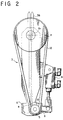
- the folding and cutting apparatus 2 is provided with an oscillatory shooter assembly 3, which is swingable in a pendulum motion in a perpendicular plane about a rotation fulcrum O 1 by a driving means, not shown.
- a counter (pressure receive) roller 4 and a nozzle roller 5 opposing thereto are formed to a front end portion of the oscillatory shooter assembly 3.
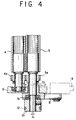
- the nozzle roller 5 and an associated structure is shown in Fig. 3 or 4, in which the counter roller 4 is supported by a shooter frame 6.
- the nozzle roller 5 is supported by the shooter frame 6 through a bearing box 7 rotatably supported thereto.
- the rotational center O 2 of the bearing box 7 with respect to the shooter frame 6 is slightly offset by an amount ⁇ 1 of eccentricity, for example, about 1 mm, with respect to the center of a bearing 7a received in the bearing box 7, that is, the rotational center O 3 of the nozzle roller 5.
- An arm member 8 is provided for the bearing box 7 and an operation (working) cylinder 9 is coupled to the arm member 8.
- the operation cylinder 9 when the operation cylinder 9 is expanded or contracted, the bearing box 7 is rotated and the nozzle roller 5 is moved in a direction contacting to (towards) or separating (away) from the counter roller by the existence of the amount ⁇ 1 of eccentricity.
- the nozzle roller 5 is moved to a position separated from the receive roller 4 by a small distance such as a distance further smaller than a thickness of the continuous paper web 1, this position being called “first position”, and on the other hand, when the operation cylinder is extended, the nozzle roller is moved to a position forcibly contacted to the counter roller 4, this position being called “second position”.
- a driven (follower) pulley 10 is secured to one end of a shaft to which the nozzle roller 5 is mounted, and the driven pulley 10 is coupled to a driving pulley 11, through a belt 12, which is disposed coaxially with the rotation fulcrum O 1 of the oscillatory shooter assembly 3.
- the driving pulley 11 is coupled to a power shaft of the folding and cutting apparatus 2 by means of a coupling member, not shown, in a manner such that the nozzle roller 5 is driven to be rotated at a peripheral speed faster than the traveling speed of the continuous paper web 1.
- the counter roller 4 and the nozzle roller 5 are coupled together by means of gears 4a and 5a so as to rotate together in the traveling direction of the paper web 1 at the same peripheral speed. Further, it is to be noted that although the gearing conditions of these gears 4a and 5a are changed by the eccentric motion of the nozzle roller 5, it causes substantially no problem because of extremely small change of the gearing condition.
- a pair of beaters 13, 13 and a pair of screws 14, 14 are arranged, respectively, on both sides of the swinging direction of the oscillatory shooter assembly 3.
- the beaters 13, 13 and the screws 14, 14 are operated in synchronism with the oscillatory motion of the oscillatory shooter assembly 3 so as to fold the continuous paper web 1 delivered from the shooter assembly 3.
- reference numeral 15 denotes a conveyer.
- An upstream side of the oscillatory shooter assembly 3 on the paper web traveling path is constructed as a paper web cut path 17 having a perpendicular structure from the oscillatory shooter assembly 3 to a pull roller 16.
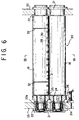
- An impression cylinder 18 and a cut cylinder 19, which constitute a cut cylinder assembly 20, are arranged in an opposing manner with the paper web cut path 17 being interposed therebetween.
- the cut cylinder assembly 20 has a structure shown in Figs. 5 to 7, in which both end portions of the impression cylinder 18 and the cut cylinder 19 are respectively supported by front and rear frames 23 to be rotatable through bearing boxes 21 and 22 in which bearings 21a and 22a are housed.
- the impression cylinder 18 and the cut cylinder 19 have the same diameter.
- Gears 24 and 25 are mounted to the impression cylinder 18 and the cut cylinder 19 respectively and the gear 24 mounted to the impression cylinder 18 is meshed with a driving gear 26, by which the impression cylinder 18 and the cut cylinder 19 are rotated through the gears 24 and 25 at the same peripheral speed in the traveling direction of the paper web 1 in a manner such that opposing surfaces of these cylinders 18 and 19 clamp the paper web 1 therebetween.
- the bearings 21a and 22a supporting the impression cylinder 18 and the cut cylinder 19 may be arranges so as to be directly supported by the frames 23, 23.
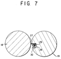
- the cut cylinder 19 is provided with a groove 28 formed to a peripheral surface thereof so as to extend in a longitudinal, i.e. axial, direction thereof, and a full-edge-type cutting blade 27 having a length extending in the full length of the cut cylinder 19 is fitted in the groove 28 and secured under force by a push plate 29 and a push bolt 30.
- the cutting blade 27 projects outward from the peripheral surface of the cut cylinder 19 by a length corresponding to a clearance S between the impression cylinder 18 and the cut cylinder 19.
- the cutting blade 27 has a structure shown in Fig. 8 and is provided with a blade edge 27a formed to the entire length portion of the blade 27 with at least one, for example, two in the illustration of Fig. 8, cutout 31 having a depth larger than the projecting length S of the blade 27.
- Grooves 32 are formed to the peripheral surface of the cut cylinder 19 at positions corresponding to the formation of the cutouts 31 of the blade 27.
- a paper web guide assembly 33 for guiding the traveling of the continuous paper web 1 passing the paper web cut path 17 is arranged to a portion perpendicular to the cut cylinder assembly 20.
- the paper web guide assembly 33 is composed of two guide wires 34a and 34b arranged oppositely to each other with respect to the paper web cut path 17 being interposed therebetween, and these guide wires 34a and 34b are disposed in the cutouts 31 formed to the cutting blade 27, respectively, as shown in Figs. 5 to 8.
- Guide roller assemblies 35a and 35b each composed of a pair of rollers are arranged at vertical upper and lower sides of the cut cylinder assembly 20 on the paper web cut path 17, respectively, and a guide device 36 is disposed by arranging a plate member between the oscillatory shooter assembly 3 and the lower guide roller assembly 35b.
- a paper web guide path 40 is arranged on the upstream side of the paper web cut path 17, and the paper web guide path 40 includes pull rollers 16, 37, a compensation roller 38, and guide rollers 39a, 39b.
- a mark sensor 41 is disposed at a position close to the guide roller 39b between the pull roller 16 and the compensation roller 38 of the paper web guide path 40.
- the cylinder diameter of the cut cylinder 19 of the cut cylinder assembly 20 is decided by the top and bottom dimension of the continuous paper web 1 to be folded as one sheet, i.e. folding pitch thereof.
- the diameter of the cut cylinder 19 is determined such that the peripheral length of the cut cylinder 19 is substantially equal to the top and bottom dimension, i.e. folding pitch of the paper web 1, and the rotational phase of the cut cylinder 19 is also determined such that the cutting blade 27 abuts against the continuous paper web 1 and performs the cutting operation to the paper web 1 by the blade edge 27a at the time when the folded portion of the continuous paper web 1 is fed to a portion between both the cylinders 18 and 19.
- the cut cylinder 19 may be exchanged.
- the cut cylinder 19 may have a cassette-type structure capable of being exchanged with respect to the frames 23 of the folding and cutting apparatus 2, and in such case, the cut cylinder 19 is exchanged together with sub-frames, not shown, supporting both the ends of the cut cylinder 19.
- the operations of the respective members and/or assemblies in association with the traveling of the continuous paper web 1 in the described embodiment can be controlled by a control means or the like which is known in this art field in a manner, for example, that the cut marks of the continuous paper web 1 is counted by a counter, which generates count signals, and operations signals are then generated to the respective members and assemblies through a controller in association with timings to the counter.
- the paper web folding and cutting apparatus of the structure according to the embodiment mentioned above will operate in the following manner.
- the continuous paper web 1 is fed along the paper web traveling path at a predetermined traveling speed.
- the continuous paper web 1, with no perforated cross line, printed and marked in the printing section is pulled into the paper web folding and cutting apparatus by means of the pull rollers 16 and 37.
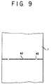
- the continuous paper web 1 in the folding and cutting apparatus 2 is fed to the paper web cut path 17 through the pull roller 37, the guide roller 39a, the compensation roller 38, the guide roller 39b and the pull roller 16 in this order, and in the cut cylinder assembly 20, cuts 42 shown in Fig. 9 are formed at every top and bottom dimension for folding and/or cutting.
- portions corresponding to the cutouts 31 of the cutting blade 27 remain at least one uncut portion 43 with respect to one line of the cuts 42.
- the cut portion is composed of the cuts 42 each having a long cut-in length and the small uncut portion 43, whereas, in the prior art mentioned in the introduction of this specification, the cut portion is composed of a cross line of perforations (fine holes) and the cuts formed in an overlapped manner.
- the continuous paper web 1 formed with the cuts 42 in the above operation passes the paper web guide assembly 33 composed of the wires 34a, 34b and is then delivered in the zigzag fashion from the nozzle roller 5 in accordance with the oscillatory motion of the oscillatory shooter assembly 3.
- the continuous paper web 1 is then bent and folded along the cuts 42 and thereafter piled up above the conveyer by the beaters 13, 13 and the screws 14, 14 while pressing down the portions at which the cuts 42 are formed.
- the continuous paper web 1 is bent and folded at the portions at which the cuts 42 are formed and small uncut portions remain, so that the continuous paper web 1 formed with such cuts 42 and uncuts 43 can be more easily bent in comparison with the paper web formed with the cross line of perforations, and moreover, can be folded with less expansion because of the existence of the uncuts 43, thus being substantially completely folded and piled up. Furthermore, because air which may stay in the bent portions will be easily discharged through the cuts 42, the expansion at the bent portions can be effectively prevented without forming curled portions to the upper surface of folded and piled set products.
- the portion of the continuous paper web 1 downstream side of the cuts 42 thereof is pulled under tension by the nozzle roller 5 and the counter roller 4 and the uncuts 43 are therefore torn, whereby the continuous paper web 1 can be cut along the cut portion formed with the cuts 42 and uncuts 43.
- the operation cylinder 9 is immediately moved reversely in the eccentric manner in the direction to release the pressing force of the nozzle roller 5 to the counter roller 4. Accordingly, the front end portion of the cut continuous paper web 1 is swung outward by the nozzle roller as it is.
- the cut portion of the continuous paper web 1 is quickly pressed by means of the beaters 13, 13 and the screws 14, 14, so that the cut paper web can be folded clearly without being disturbed.
- the impression cylinder 18 and the cut cylinder 19 of the cut cylinder assembly 20 are connected to an output shaft of a printing press including the folding and cutting apparatus, the rotational speeds of these cylinders 18 and 19 are set so that the peripheral speeds thereof substantially accord with the traveling speed of the continuous paper web 1, and as mentioned before, the peripheral length of the cut cylinder 19 is made equal to the interval between the bent portions of the continuous paper web 1.
- Fig. 10 is a timing chart showing the pressing operation of the nozzle roller after the detection of the cut mark by the mark sensor, the non-pressing (releasing) operation of the nozzle roller, and the operation of the operation cylinder for the nozzle roller.
- the continuous paper web can be bent and folded with no protuberant portion at the bent portion, and the set products discharged after the cutting do not provide any expanded or protuberant portion, thus providing a product with no curl. According to such merits, the operations and workings can be made easy and simple and members or parts to be used can be effectively reduced.
Landscapes
- Folding Of Thin Sheet-Like Materials, Special Discharging Devices, And Others (AREA)
Abstract
Description
wherein the continuous paper web is cut along the cut portions to be cut therefrom by pressing the nozzle roller against the counter roller at a timing when the cut portion to be cut approaches just before an upstream side portion of both the nozzle roller and counter roller.
Claims (8)
- A paper web folding and cutting apparatus, comprising:a paper web traveling path enabling a continuous paper web to travel at a predetermined traveling speed;means disposed on the paper web traveling path and adapted to form a cut portion formed as a line of a plurality of cuts, having at least one uncut portion, at every top and bottom directional dimension of the continuous paper web to be folded; andan oscillatory shooter assembly disposed on the paper web traveling path at a portion downstream side of the cut forming means in a paper web traveling direction, said oscillatory shooter assembly being provided with a counter roller and a nozzle roller at a lower end portion thereof, which are rotated at a peripheral speed faster than the paper web traveling speed, said nozzle roller being contacted to and separated from said counter roller, and said oscillatory shooter assembly performing an oscillatory motion in a bilateral direction in a state that the continuous paper web is interposed between said nozzle roller and said counter roller so as to fold in a zigzag fashion the continuous paper web along the cut portions,
wherein the continuous paper web is cut along the cut portions to be cut therefrom by pressing the nozzle roller against the counter roller at a timing when the cut portion to be cut approaches just before an upstream side portion of both the nozzle roller and counter roller. - A paper web folding and cutting apparatus according to claim 1, wherein said means for forming a cut portion comprises a paper web cut path disposed on an upstream side of the oscillatory shooter assembly and a cut cylinder assembly composed of an impression cylinder and a cut cylinder which are arranged on both sides of the paper web cut path in an opposed manner.
- A paper web folding and cutting apparatus according to claim 2, wherein said impression cylinder and said cut cylinder have substantially the same diameter and are rotated at a same peripheral speed in a paper web traveling direction with the continuous paper web being interposed therebetween.
- A paper web folding and cutting apparatus according to claim 2, wherein a cutting blade is mounted to the cut cylinder so as to extend in a longitudinal direction thereof for forming a line of cuts as the cut portion along which the continuous paper web is folded and cut, said cutting blade being formed with at least one cutout for forming at least one uncut portion to the cut portion.
- A paper web folding and cutting apparatus according to claim 1, wherein said nozzle roller is supported by a frame member through a bearing means to be rotatable and a rotational center of the bearing means with respect to the frame member is offset from a rotational center of the nozzle roller.
- A paper web folding and cutting apparatus according to claim 1, further comprising a control means for controlling a timing for pressing the nozzle roller against the counter roller.
- A paper web folding and cutting apparatus according to claim 6, wherein said nozzle roller is pressed against the counter roller at a timing when a plurality of set sheets of the continuous paper web are folded by the oscillatory shooter assembly.
- A paper web and folding and cutting apparatus according to claim 1 being applicable to a form printing press.
Applications Claiming Priority (2)
| Application Number | Priority Date | Filing Date | Title |
|---|---|---|---|
| JP26959897 | 1997-10-02 | ||
| JP26959897A JP3743925B2 (en) | 1997-10-02 | 1997-10-02 | Paper cutting device |
Publications (2)
| Publication Number | Publication Date |
|---|---|
| EP0924151A2 true EP0924151A2 (en) | 1999-06-23 |
| EP0924151A3 EP0924151A3 (en) | 1999-06-30 |
Family
ID=17474602
Family Applications (1)
| Application Number | Title | Priority Date | Filing Date |
|---|---|---|---|
| EP98117808A Withdrawn EP0924151A3 (en) | 1997-10-02 | 1998-09-19 | Paper web folding and cutting apparatus |
Country Status (3)
| Country | Link |
|---|---|
| US (1) | US6669617B1 (en) |
| EP (1) | EP0924151A3 (en) |
| JP (1) | JP3743925B2 (en) |
Families Citing this family (7)
| Publication number | Priority date | Publication date | Assignee | Title |
|---|---|---|---|---|
| US7441681B2 (en) * | 2003-08-29 | 2008-10-28 | The Procter & Gamble Company | Apparatus for separating a web material |
| JP5057514B2 (en) * | 2007-09-19 | 2012-10-24 | 株式会社ミヤコシ | Booklet product manufacturing apparatus and booklet product manufacturing method |
| TWI512848B (en) * | 2008-07-18 | 2015-12-11 | United Test & Assembly Ct Lt | Packaging structural member |
| JP5123232B2 (en) * | 2009-03-10 | 2013-01-23 | 株式会社トーヨーパッケン | Noodle line folding supply device |
| RU2567023C1 (en) * | 2011-08-31 | 2015-10-27 | Ска Хайджин Продактс Аб | Pile of folded sanitary articles, method and device for its making |
| US8939877B2 (en) * | 2012-01-18 | 2015-01-27 | Century Printing & Packaging, Inc. | Method and apparatus for forming fan-folded web of labels with improved registration |
| CN113771525B (en) * | 2021-09-13 | 2023-03-24 | 武汉鸿印社科技有限公司 | Automatic book printing device of folding concatenation |
Citations (2)
| Publication number | Priority date | Publication date | Assignee | Title |
|---|---|---|---|---|
| US5076555A (en) * | 1990-07-25 | 1991-12-31 | Bunch Jr Earnest B | Apparatus for partially severing strip of paper along lines offset from lines of weakening in the paper |
| JPH0976460A (en) * | 1995-09-13 | 1997-03-25 | Miyakoshi:Kk | Paper cutting device in folding device for form printing machine |
Family Cites Families (6)
| Publication number | Priority date | Publication date | Assignee | Title |
|---|---|---|---|---|
| US5201700A (en) * | 1988-11-07 | 1993-04-13 | Industria Grafica Meschi S.R.L. | Method for folding material fed from a continuous band into accordion-like manner at a high speed |
| JPH0541822A (en) | 1991-08-07 | 1993-02-19 | Canon Inc | Video camera |
| BE1006092A3 (en) * | 1992-07-15 | 1994-05-10 | Web Converting Equip | Machine for the zig-zag folding a strip. |
| US5348527A (en) * | 1992-09-01 | 1994-09-20 | Rdp Marathon Inc. | Apparatus for cutting and stacking a multi-form web |
| JPH0818750A (en) | 1994-06-24 | 1996-01-19 | Ricoh Co Ltd | Picture reader |
| DE19528077A1 (en) | 1995-07-31 | 1997-02-06 | Rapid Maschbau Gmbh | Device for automatically cutting components |
-
1997
- 1997-10-02 JP JP26959897A patent/JP3743925B2/en not_active Expired - Fee Related
-
1998
- 1998-09-19 EP EP98117808A patent/EP0924151A3/en not_active Withdrawn
- 1998-09-24 US US09/159,767 patent/US6669617B1/en not_active Expired - Lifetime
Patent Citations (2)
| Publication number | Priority date | Publication date | Assignee | Title |
|---|---|---|---|---|
| US5076555A (en) * | 1990-07-25 | 1991-12-31 | Bunch Jr Earnest B | Apparatus for partially severing strip of paper along lines offset from lines of weakening in the paper |
| JPH0976460A (en) * | 1995-09-13 | 1997-03-25 | Miyakoshi:Kk | Paper cutting device in folding device for form printing machine |
Non-Patent Citations (1)
| Title |
|---|
| PATENT ABSTRACTS OF JAPAN vol. 097, no. 007, 31 July 1997 & JP 09 076460 A (MIYAKOSHI:KK), 25 March 1997 & EP 0 763 492 A (MIYAKOSHI PRINTING MACHINERY CO. LTD.) * |
Also Published As
| Publication number | Publication date |
|---|---|
| EP0924151A3 (en) | 1999-06-30 |
| JP3743925B2 (en) | 2006-02-08 |
| US6669617B1 (en) | 2003-12-30 |
| JPH11106129A (en) | 1999-04-20 |
Similar Documents
| Publication | Publication Date | Title |
|---|---|---|
| EP0420297A1 (en) | Processing paper and other webs | |
| US3981213A (en) | Rotary sheet material cutter and creaser | |
| EP0159717B1 (en) | Receiving and stacking apparatus for strips of sheet material | |
| US5123890A (en) | Apparatus and method for separating forms in a stack | |
| JPH0750194Y2 (en) | Rotary Sha | |
| US5383836A (en) | Letter sheet forming apparatus | |
| EP0924151A2 (en) | Paper web folding and cutting apparatus | |
| US5365843A (en) | Printing press with web breaking assembly | |
| US4190478A (en) | Process and apparatus for production of faced or laminated sheets | |
| JP3020138B2 (en) | Paper cutting device in folding device of form printing machine | |
| EP0239650B1 (en) | Intermittent feeding apparatus for a continuous sheet | |
| US6895845B2 (en) | Rotary sheeter having an improved vacuum means for cross trim removal | |
| JP2582023Y2 (en) | Folding introduction unit with forma sewing machine for folder | |
| CA2122671C (en) | Document folding machine employing a flap | |
| US6458066B1 (en) | Linear folding device and method | |
| JP3166087B2 (en) | Method and apparatus for inserting sewing machine for Asiro binding | |
| JP4225000B2 (en) | Folding envelope creation device | |
| JP2511896Y2 (en) | Continuous paper cutting device in form printing machine | |
| JP3033627B2 (en) | Metal strip slitting equipment | |
| SU738916A1 (en) | Fly lead making machine | |
| JP4412707B2 (en) | Seal writing device | |
| US5019030A (en) | Envelope blank forming machine | |
| US5100371A (en) | Envelope blank forming machine | |
| AU631767B2 (en) | Processing paper and other webs | |
| JPH0620768Y2 (en) | Electronic paper separation device |
Legal Events
| Date | Code | Title | Description |
|---|---|---|---|
| PUAI | Public reference made under article 153(3) epc to a published international application that has entered the european phase |
Free format text: ORIGINAL CODE: 0009012 |
|
| PUAL | Search report despatched |
Free format text: ORIGINAL CODE: 0009013 |
|
| AK | Designated contracting states |
Kind code of ref document: A2 Designated state(s): DE FR GB IT NL SE |
|
| AX | Request for extension of the european patent |
Free format text: AL;LT;LV;MK;RO;SI |
|
| AK | Designated contracting states |
Kind code of ref document: A3 Designated state(s): AT BE CH CY DE DK ES FI FR GB GR IE IT LI LU MC NL PT SE |
|
| AX | Request for extension of the european patent |
Free format text: AL;LT;LV;MK;RO;SI |
|
| 17P | Request for examination filed |
Effective date: 19991110 |
|
| AKX | Designation fees paid |
Free format text: DE FR GB IT NL SE |
|
| 17Q | First examination report despatched |
Effective date: 20020403 |
|
| STAA | Information on the status of an ep patent application or granted ep patent |
Free format text: STATUS: THE APPLICATION IS DEEMED TO BE WITHDRAWN |
|
| 18D | Application deemed to be withdrawn |
Effective date: 20020716 |