EP0923992A2 - Cyclonic separating apparatus - Google Patents
Cyclonic separating apparatus Download PDFInfo
- Publication number
- EP0923992A2 EP0923992A2 EP98310373A EP98310373A EP0923992A2 EP 0923992 A2 EP0923992 A2 EP 0923992A2 EP 98310373 A EP98310373 A EP 98310373A EP 98310373 A EP98310373 A EP 98310373A EP 0923992 A2 EP0923992 A2 EP 0923992A2
- Authority
- EP
- European Patent Office
- Prior art keywords
- cyclone
- separating apparatus
- cyclonic separating
- entry
- airflow
- Prior art date
- Legal status (The legal status is an assumption and is not a legal conclusion. Google has not performed a legal analysis and makes no representation as to the accuracy of the status listed.)
- Granted
Links
Images

Classifications
-
- A—HUMAN NECESSITIES
- A47—FURNITURE; DOMESTIC ARTICLES OR APPLIANCES; COFFEE MILLS; SPICE MILLS; SUCTION CLEANERS IN GENERAL
- A47L—DOMESTIC WASHING OR CLEANING; SUCTION CLEANERS IN GENERAL
- A47L9/00—Details or accessories of suction cleaners, e.g. mechanical means for controlling the suction or for effecting pulsating action; Storing devices specially adapted to suction cleaners or parts thereof; Carrying-vehicles specially adapted for suction cleaners
- A47L9/10—Filters; Dust separators; Dust removal; Automatic exchange of filters
- A47L9/16—Arrangement or disposition of cyclones or other devices with centrifugal action
- A47L9/1616—Multiple arrangement thereof
- A47L9/1625—Multiple arrangement thereof for series flow
- A47L9/1633—Concentric cyclones
-
- A—HUMAN NECESSITIES
- A47—FURNITURE; DOMESTIC ARTICLES OR APPLIANCES; COFFEE MILLS; SPICE MILLS; SUCTION CLEANERS IN GENERAL
- A47L—DOMESTIC WASHING OR CLEANING; SUCTION CLEANERS IN GENERAL
- A47L9/00—Details or accessories of suction cleaners, e.g. mechanical means for controlling the suction or for effecting pulsating action; Storing devices specially adapted to suction cleaners or parts thereof; Carrying-vehicles specially adapted for suction cleaners
- A47L9/10—Filters; Dust separators; Dust removal; Automatic exchange of filters
- A47L9/16—Arrangement or disposition of cyclones or other devices with centrifugal action
- A47L9/165—Construction of inlets
-
- B—PERFORMING OPERATIONS; TRANSPORTING
- B04—CENTRIFUGAL APPARATUS OR MACHINES FOR CARRYING-OUT PHYSICAL OR CHEMICAL PROCESSES
- B04C—APPARATUS USING FREE VORTEX FLOW, e.g. CYCLONES
- B04C5/00—Apparatus in which the axial direction of the vortex is reversed
- B04C5/02—Construction of inlets by which the vortex flow is generated, e.g. tangential admission, the fluid flow being forced to follow a downward path by spirally wound bulkheads, or with slightly downwardly-directed tangential admission
- B04C5/04—Tangential inlets
Definitions
- the invention relates to cyclonic separating apparatus, particularly but not exclusively to cyclonic vacuum cleaners.
- An object of the invention is provide cyclonic separating apparatus which is capable of maintaining a minimum cross-sectional area of fluid flow whilst minimising its overall dimensions. It is a further object of the present invention to provide a vacuum cleaner which is more compact than other vacuum cleaners. A further object is to provide cyclonic separating apparatus having increased efficiency and/or which has fewer losses than similar known separating apparatus. A still further object is to provide cyclonic separating apparatus in which the particles entrained in the fluid flow entering the cyclone are closer to the cyclone wall than in known apparatus.
- the invention provides cyclonic separating apparatus as claimed in claim 1. Further and advantageous features are set out in the subsidiary claims.
- the invention also provides a vacuum cleaner as set out in claim 11.
- Providing two or more points of entry to the interior of the cyclone surface effectively spreads the inlet over a greater proportion of the circumference of the cyclone surface . If two points of entry are provided, the radial dimension necessary to achieve the minimum cross-sectional area of the airflow can be reduced by one half without affecting the axial dimension of the points of entry. If ten points of entry are provided, the necessary radial dimension is only one tenth of that previously required. The previously necessary transfer port can be dispensed with and a substantial reduction in the width of the machine can be achieved.
- the fluid flow entering the cyclonic separating apparatus is much closer to the cyclone wall than in known arrangements and is also less turbulent than that entering similar apparatus having only one point of entry.
- the points of entry are equispaced about the longitudinal axis of the cyclone. This axi-symmetrical arrangement stabilises the flow in the cyclone and improves the separation efficiency.
- Each point of entry consists of a longitudinal slot for directing fluid into the cyclone in a tangential manner.
- a vane is provided for smoothly directing fluid through each slot.
- This type of arrangement is easily constructed by moulding in a plastics material and is thus economical and maintenance free.
- the arrangement dispenses with the need for a scroll-type transfer port when the apparatus forms part of a vacuum cleaner having two cyclonic separators, thereby reducing the length of the airflow path between the separators and reducing power losses due to friction.
- the airflow entering the cyclone is also more axi-symmetric than in separators having a single tangential entry.
- Figure 1 illustrates schematically known cyclonic separating apparatus of the type suitable for use in cyclonic vacuum cleaners.
- the separating apparatus is illustrated for reasons of clarity.
- a motor or fan unit capable of drawing an airflow from the dirty air inlet, through the separating apparatus, to the clean air outlet will be provided, normally downstream of the separating apparatus but upstream of the clean air outlet.
- the motor or fan unit will normally be positioned within the airflow path so as to make use of the airflow to cool the motor.
- the known separating apparatus 10 incorporates an outer cyclone 12 and an inner cyclone 14.
- the constructional details are set out below.
- the cyclonic separating apparatus 10 comprises an upper annular plate 16.
- a cylindrical vortex finder 18 in the form of a cylindrical tube extends through the annular plate 16 so as to project both into the interior of the cyclonic separating apparatus 10 and upwards beyond the annular plate 16.
- the cylindrical vortex finder 18 includes at its upper end means for connecting the cyclonic separating apparatus 10 to the downstream airflow path of the apparatus, although the connecting means are not shown for reasons of clarity.
- the cylindrical vortex finder 18 projects into the cyclonic separating apparatus 10 to a distance equal to approximately 0.9 times the external diameter of the annular plate 16.
- the inner cyclone 14 Depending from the annular plate 16 is the inner cyclone 14.
- the inner cyclone 14 consists of an upper cylindrical portion 14a and a frusto-conical portion 14b.
- the upper cylindrical portion 14a terminates at a level above the lower end of the cylindrical vortex finder 18.
- the frusto-conical portion 14b of the inner cyclone 14 tapers downwardly and terminates in a cone opening 20.
- the diameter of the cone opening 20 is no greater than the diameter of the cylindrical vortex finder 18.
- the shroud 24 Located radially outwardly of the inner cyclone 14 is a shroud 24.
- the shroud 24 has an outer annular flange 24a, a frusto-conical portion 24b, a perforated cylindrical portion 24c and an inner annular flange 24d.
- the inner annular flange 24d is sealed in an airtight manner to the frusto-conical portion 14b of the inner cyclone 14.
- the perforated cylindrical portion 24c extends upwardly towards the annular plate 16 from the outer edge of the inner annular flange 24d.
- the frusto-conical portion 24b lies substantially parallel to but spaced from the frusto-conical portion 14b of the inner cyclone 14 so that an annular passageway is formed between the two frusto-conical portions 14b and 24b.
- the outer annular flange 24a extends between the upper edge of the frusto-conical portion 24b of the shroud 24 and terminates in register with the outer edge of the annular plate 16.
- a cylindrical bin 26 depends from the annular plate 16.
- the cylindrical bin 26 is sealed in an airtight manner to the outer edge of the annular plate 16.
- the outer annular flange 24a of the shroud also seals in an airtight manner against the wall of the cylindrical bin 26.
- An annular chamber 22 is thereby created radially outwardly of the frusto-conical portion 14b of the shroud 14 and is bounded on the other three sides by the cylindrical bin 26, the outer annular flange 24a of the shroud 24 and an annular sealing flange 23.
- the annular passageway between the two frusto-conical portions 14b and 24b forms an inlet to the annular chamber 22.
- a transfer port 27 extending beyond the cylindrical bin 26 provides an outlet from the annular chamber 22.
- the transfer port 27 provides a tangential air inlet in the wall of the upper cylindrical portion 14a so that air entering the inner cyclone 14 flows tangentially to the wall of the upper cylindrical portion 14a.
- the transfer port 27 must have a sufficiently large cross sectional area to ensure that the free flow of air within the apparatus 10 is not hindered.
- the base 28 of the cylindrical bin 26 is formed integrally with the cylindrical bin 26 or can be removable to allow emptying.
- Surfaces 30 extend between a portion of the cylindrical bin 26 near the base 28 and a portion of the frusto-conical portion 14b of the inner cyclone 14 a little above the cone opening 20.
- the surfaces 30 divide the interior of the cylindrical bin so as to form a first dust collecting area 32 for the first or outer cyclone 12 and a second dust collecting area 34 for the second or inner cyclone 14.
- An upstream tangential air inlet 40 is arranged in the wall of the cylindrical bin 26 immediately below the outer annular flange 24a of the shroud 24.
- the upstream tangential air inlet 40 provides an inlet to the outer cyclone 12 to allow the introduction of the airflow between the wall of the cylindrical bin 26 and the frusto-conical portion 24b of the shroud 24.
- the upstream tangential air inlet 40 has a lower edge 42 which is located upwardly of the upper edge of the perforated cylindrical portion 24c of the shroud 24.
- the cross-sectional area of the upstream tangential air inlet immediately upstream of the cyclonic separating apparatus is substantially 800mm 2 or another suitable value, depending upon the specific characteristics of the machine in which the apparatus is used.
- the air then passes along the annular passageway between the frusto-conical portion 24b of the shroud 24 and the frusto-conical portion 14b of the inner cyclone 14. It passes into the annular chamber 22 and from there along the transfer port 27 to the tangential air inlet to the inner cyclone 14 and the helical motion of the accelerating airflow down the frusto-conical portion 14b causes very high speeds to be attained and dirt and dust particles to be separated from the airflow. As the air passes through the cone opening 20 into the second dust collecting area 34, further dirt and dust particles still entrained in the airflow are separated and collected whilst clean air travels back through the cone opening 20 and exits the cyclonic separating apparatus 10 via the cylindrical vortex finder 18.
- the dimensions of the cyclonic separating apparatus 10 cannot be reduced to any great extent, particularly the diameter of the apparatus in the region of the upper end of the inner cyclone 14.
- the transfer port 27 forms the only inlet to the inner cyclone 14 and therefore the cross-sectional area of the airflow path at this point and immediately upstream thereof must be maintained at or above a specific minimum value, for example between 500mm 2 and 1000mm 2 . If the diameter of the cyclonic separating apparatus 10 were reduced at this point, an unacceptable elongation of the apparatus 10 in the direction of the longitudinal axis thereof would be necessary.
- the length of the airflow path between the outer cyclone 12 and the inner cyclone 14 is considerable. Air moving upwardly along the annular passageway between the frusto-conical portion 24b of the shroud 24 and the frusto-conical portion 14b of the inner cyclone 14 enters the annular chamber 22 and is then forced to circulate around the annular chamber 22 before entering the inner cyclone 14 via the transfer port 27. The friction losses due to the passage of air around the annular chamber 22 can be substantial.
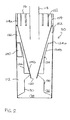
- Figure 2 is a schematic sectional side view of cyclonic separating apparatus 110 similar to that shown in Figure 1, from which a comparison of the invention and the prior art can be made. Many of the components of the apparatus 110 shown in Figure 2 are essentially the same as the corresponding components shown in Figure 1. The essential differences are described below.
- the upper cylindrical portion 114a of the inner cyclone 114 has, in the embodiment of the invention, a plurality of points of entry 152 spaced about the longitudinal axis of the apparatus 110 so as to allow air passing along the annular passageway between the frusto-conical portion 124b of the shroud 124 and the frusto-conical portion 114b of the inner cyclone 114 to pass directly into the inner cyclone 114 in a tangential manner.
- the details of the arrangement of the upper cylindrical portion 114a will be described further below.
- the ability to pass the air directly from the annular passageway to the inner cyclone 114 removes the need for a scroll-type inlet or transfer port which forms part of the airflow path of the apparatus illustrated in Figure 1. Not only does the omission of the inlet allow the radial dimension of the apparatus to be reduced and simplify the construction of the apparatus as a whole, but reducing the length of the airflow path may reduce power losses due to friction.
- dirty air enters the outer cyclone 112 via the tangential air inlet 140.
- the dirty air spirals around the outer wall of the cylindrical bin 126 and moves downwardly in a helical manner causing separation of dirt and debris from the airflow due to centrifugal forces.
- the air then moves inwardly and upwardly across the surfaces 130 and passes through the perforations in the perforated cylindrical portion 124c of the shroud 124. A substantial amount of dirt and debris is left in the first dust collecting area 132.
- the airflow then passes along the annular passageway between the frusto-conical portion 124b and the frusto-conical portion 114b. It enters the cylindrical passageway 122 formed between inner cyclone 114 and the upper portion of the cylindrical bin 126.
- the air is then immediately directed, by means of vanes 154, through a plurality of longitudinal slots 152 in the upper cylindrical portion 114a of the inner cyclone 114 and is directed in a tangential manner into the inner cyclone 114.
- the air then spirals down the inner surface of the inner cyclone 114 and the helical motion of the airflow causes very high speeds to be attained and dirt and dust particles to be separated.
- the cylindrical bin 126 can be made removable to allow the first and second dust collecting areas 132,134 to be emptied.
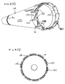
- Figures 3a and 3b are perspective and plans views, respectively, of the inner cyclone 114 forming part of the apparatus 110 illustrated in Figure 2.
- the inner cyclone 114 has an upper cylindrical portion 114a and a frusto-conical portion 114b, the frusto-conical portion 114b incorporating a circular groove 114c for receiving, in a snap-fit manner, the inner edge of the inner annular flange 124d of the shroud 124 illustrated in Figure 2.
- the upper cylindrical portion 114a incorporates a plurality of helically offset panel portions 150 equispaced about the upper cylindrical portion 114a.
- ten panel portions 150 are illustrated.
- the number of panel portions 150 can be varied to suit requirements. For example, as few as four or as many as twenty four panel portions could be provided.
- Each panel portion 150 is arranged such that its leading edge is radially spaced further away from the longitudinal axis of the inner cyclone 114 than its trailing edge. Thus, each panel portion 150 lies along a substantially helical path.
- a longitudinal slot 152 is formed between the trailing edge of a first panel portion and the leading edge of the subsequent panel portion 150, seen in the direction of the airflow.
- the combined area of the longitudinal slots 152 is no less than the specified minimum diameter of the airflow path of the apparatus 110.
- the specified minimum airflow cross-sectional area is 800mm 2
- each longitudinal slot 152 must have an effective cross-sectional area of at least 80mm 2 .
- each panel portion 150 are shaped so as to minimise losses due to friction when an airflow passes across the panel portions 150.
- the preferred cross-sectional shape of each panel portion is generally aerofoil shaped.
- the leading edge of each panel portion 150 is generally rounded and the trailing edge of each panel portion 150 is generally tapered.
- each vane 154 Located on the radially external face of each panel portion 150 is an arcuate vane 154.
- Each vane 154 has a lower portion 154a which begins generally in register with the intersection between the frusto-conical portion 114b and the upper cylindrical portion 114a of the inner cyclone 114.
- the lower portion 154a extends generally parallel to the longitudinal axis of the inner cyclone 114 and then merges with an arcuate upper portion 154b which extends from the lower portion 154a towards the trailing edge of the relevant panel portion 150.
- Each vane 154 extends radially outwardly from the outer surface of the respective panel portion 150 towards the upper portion of the cylindrical bin 126, which is located radially outwardly of the inner cyclone 114.
- the vanes 154 extend sufficiently far radially outwardly to make contact with the cylindrical bin 126 and, preferably, the vanes 154 abut against the cylindrical bin 126 in an airtight manner.
- contact with the cylindrical bin 126 is not essential. Indeed, the vanes 154 can be omitted altogether if desired.
- Location means 160 can be provided in the form of a blind recess located in one of the panel portions 150 for ensuring that the inner cyclone 114 is orientated correctly with regard to the remainder of the apparatus 110. However, the location means 160 do not form part of the invention currently under discussion.
- the entire inner cyclone 114 as illustrated in Figures 3a and 3b can easily be moulded from a plastics material without undue difficulty.
- the inner cyclone 114 can therefore replace the inner cyclone 14 illustrated in Figure 1 with the resultant advantages of reduced losses, reduced dimensions and simplicity of construction.
- the air passing along the annular passageway between the frusto-conical portions 114b and 124b is immediately directed by means of the vanes 154 through the longitudinal slots 152 and onto the inner surface of the inner cyclone 114.
- the flow in the inner cyclone 114 is also less turbulent because of the axi-symmetrical arrangement of the inlet ports and this increases the separation efficiency of the cyclone.
- a further advantage of the arrangement shown in Figures 2 and 3 is the fact that all of the air entering the inner cyclone 114 is relatively close to the cyclone wall on entry. Since the time required to separate a particle from the airflow will be dependent on the initial distance of that particle from the wall, separation of particles from the airflow will be more rapid when using the apparatus of the invention than other apparatus in which at least some of the airflow enters the cyclone spaced further from the wall.
- the vortex finder could be considerably shorter and need not project above the annular plate.
- the base of the cylindrical bin cold be made conical or frusto-conical and other relative dimensions could be altered without departing from the scope of the invention.
- vanes directing air into the longitudinal slots need not be included.
- the principles of the invention can be applied to cyclonic separators for use in areas other than vacuum cleaners and, indeed, for use in separating particulates from flows of fluids other than air.
Abstract
Description
- The invention relates to cyclonic separating apparatus, particularly but not exclusively to cyclonic vacuum cleaners.
- There is an ever-present demand for consumer goods to be compact, to require minimum maintenance and to achieve maximum performance. The area of vacuum cleaners is no exception. However, it is also desirable for the cross-sectional area of the flow path inside a vacuum cleaner to be maintained at or above a specified minimum value. For cyclonic vacuum cleaners, currently enjoying considerable popularity in the UK and other countries, a typical minimum cross-sectional area for the flow path is between 500mm2 and 1000mm2 depending upon the specific dimensions and performance characteristics of each machine. Maintaining a cross-sectional area within this range of values presents no problem in most portions of the vacuum cleaner but the tangential entry into the cyclone and the airflow path immediately upstream thereof is a portion of the machine in which the maintenance of the minimum area can affect the overall dimensions of the machine. It can also extend the length of the flow path beyond that which would otherwise be desirable.
- Attempts have been made to "slim down" cyclonic vacuum cleaners. However, there must be an adequate cross-sectional area provided immediately upstream of the tangential entry to allow the airflow path, which passes outside the overall diameter of the cyclone upstream of the tangential entry, to maintain its minimum cross-sectional area. This either prevents any reduction of the radial dimension of the machine which might otherwise have been desirable or introduces an awkward and unsightly bulge or enlargement into the apparatus. The problem is particularly acute in the area of the inlet to the inner cyclone in vacuum cleaners incorporating two concentric cyclones. Another disadvantage of known tangential entries into cyclonic vacuum cleaners and other separators is that at least part of the airflow entering the cyclone will be spaced from the cyclone wall by a considerable distance and any particles entrained in that part of the airflow will take longer to reach the wall and become separated than is desirable. Furthermore, the need to convert an airflow previously moving helically along an annular path into a generally linear airflow immediately upstream of the inner cyclone requires the provision of a length of conduit or ducting, commonly referred to as the transfer port, sufficient to achieve the change. Losses occur in such conduits due to friction. It would therefore be generally advantageous to avoid including the transfer port so as to reduce the overall dimensions of the apparatus, and also to reduce the ultimate length of the airflow path and thereby reduce losses due to friction. It would also be advantageous to introduce more of the airflow closer to the cyclone wall than is currently possible. These principles apply in cyclonic separating apparatus other than vacuum cleaners.
- An object of the invention is provide cyclonic separating apparatus which is capable of maintaining a minimum cross-sectional area of fluid flow whilst minimising its overall dimensions. It is a further object of the present invention to provide a vacuum cleaner which is more compact than other vacuum cleaners. A further object is to provide cyclonic separating apparatus having increased efficiency and/or which has fewer losses than similar known separating apparatus. A still further object is to provide cyclonic separating apparatus in which the particles entrained in the fluid flow entering the cyclone are closer to the cyclone wall than in known apparatus.
- The invention provides cyclonic separating apparatus as claimed in claim 1. Further and advantageous features are set out in the subsidiary claims. The invention also provides a vacuum cleaner as set out in claim 11.
- Providing two or more points of entry to the interior of the cyclone surface effectively spreads the inlet over a greater proportion of the circumference of the cyclone surface . If two points of entry are provided, the radial dimension necessary to achieve the minimum cross-sectional area of the airflow can be reduced by one half without affecting the axial dimension of the points of entry. If ten points of entry are provided, the necessary radial dimension is only one tenth of that previously required. The previously necessary transfer port can be dispensed with and a substantial reduction in the width of the machine can be achieved. The fluid flow entering the cyclonic separating apparatus is much closer to the cyclone wall than in known arrangements and is also less turbulent than that entering similar apparatus having only one point of entry. Preferably, the points of entry are equispaced about the longitudinal axis of the cyclone. This axi-symmetrical arrangement stabilises the flow in the cyclone and improves the separation efficiency.
- Each point of entry consists of a longitudinal slot for directing fluid into the cyclone in a tangential manner. A vane is provided for smoothly directing fluid through each slot. This type of arrangement is easily constructed by moulding in a plastics material and is thus economical and maintenance free. The arrangement dispenses with the need for a scroll-type transfer port when the apparatus forms part of a vacuum cleaner having two cyclonic separators, thereby reducing the length of the airflow path between the separators and reducing power losses due to friction. The airflow entering the cyclone is also more axi-symmetric than in separators having a single tangential entry.
- An embodiment of the invention will now be described by way of example only and with reference to the accompanying drawings, wherein:
- Figure 1 is a schematic sectional side view of cyclonic separating apparatus according to the prior art;
- Figure 2 is a schematic sectional side view of cyclonic separating apparatus incorporating the present invention; and
- Figures 3a and 3b are perspective and plan views respectively of a component of the apparatus of Figure 2 from which the details of the invention as embodied can clearly be seen.
-
- Figure 1 illustrates schematically known cyclonic separating apparatus of the type suitable for use in cyclonic vacuum cleaners. In Figure 1, only the separating apparatus is illustrated for reasons of clarity. When the apparatus forms part of a vacuum cleaner, at least one dirty air inlet will be arranged upstream of the illustrated separating apparatus and a clean air outlet will be arranged downstream thereof. A motor or fan unit capable of drawing an airflow from the dirty air inlet, through the separating apparatus, to the clean air outlet will be provided, normally downstream of the separating apparatus but upstream of the clean air outlet. The motor or fan unit will normally be positioned within the airflow path so as to make use of the airflow to cool the motor. However, these details do not affect the present invention and therefore they will not be described in any further detail here.
- As illustrated, the known separating
apparatus 10 incorporates anouter cyclone 12 and an inner cyclone 14. The constructional details are set out below. - The cyclonic
separating apparatus 10 comprises an upperannular plate 16. A cylindrical vortex finder 18 in the form of a cylindrical tube extends through theannular plate 16 so as to project both into the interior of the cyclonicseparating apparatus 10 and upwards beyond theannular plate 16. Thecylindrical vortex finder 18 includes at its upper end means for connecting the cyclonic separatingapparatus 10 to the downstream airflow path of the apparatus, although the connecting means are not shown for reasons of clarity. The cylindrical vortex finder 18 projects into the cyclonic separatingapparatus 10 to a distance equal to approximately 0.9 times the external diameter of theannular plate 16. - Depending from the
annular plate 16 is the inner cyclone 14. The inner cyclone 14 consists of an uppercylindrical portion 14a and a frusto-conical portion 14b. The uppercylindrical portion 14a terminates at a level above the lower end of thecylindrical vortex finder 18. The frusto-conical portion 14b of the inner cyclone 14 tapers downwardly and terminates in a cone opening 20. The diameter of the cone opening 20 is no greater than the diameter of thecylindrical vortex finder 18. - Located radially outwardly of the inner cyclone 14 is a shroud 24. The
shroud 24 has an outer annular flange 24a, a frusto-conical portion 24b, a perforated cylindrical portion 24c and an innerannular flange 24d. The innerannular flange 24d is sealed in an airtight manner to the frusto-conical portion 14b of the inner cyclone 14. The perforated cylindrical portion 24c extends upwardly towards theannular plate 16 from the outer edge of the innerannular flange 24d. The frusto-conical portion 24b lies substantially parallel to but spaced from the frusto-conical portion 14b of the inner cyclone 14 so that an annular passageway is formed between the two frusto-conical portions conical portion 24b of theshroud 24 and terminates in register with the outer edge of theannular plate 16. - A
cylindrical bin 26 depends from theannular plate 16. Thecylindrical bin 26 is sealed in an airtight manner to the outer edge of theannular plate 16. The outer annular flange 24a of the shroud also seals in an airtight manner against the wall of thecylindrical bin 26. Anannular chamber 22 is thereby created radially outwardly of the frusto-conical portion 14b of the shroud 14 and is bounded on the other three sides by thecylindrical bin 26, the outer annular flange 24a of theshroud 24 and anannular sealing flange 23. The annular passageway between the two frusto-conical portions annular chamber 22. Atransfer port 27 extending beyond thecylindrical bin 26 provides an outlet from theannular chamber 22. Thetransfer port 27 provides a tangential air inlet in the wall of the uppercylindrical portion 14a so that air entering the inner cyclone 14 flows tangentially to the wall of the uppercylindrical portion 14a. Thetransfer port 27 must have a sufficiently large cross sectional area to ensure that the free flow of air within theapparatus 10 is not hindered. - The
base 28 of thecylindrical bin 26 is formed integrally with thecylindrical bin 26 or can be removable to allow emptying.Surfaces 30 extend between a portion of thecylindrical bin 26 near thebase 28 and a portion of the frusto-conical portion 14b of theinner cyclone 14 a little above thecone opening 20. Thesurfaces 30 divide the interior of the cylindrical bin so as to form a firstdust collecting area 32 for the first orouter cyclone 12 and a seconddust collecting area 34 for the second or inner cyclone 14. - An upstream
tangential air inlet 40 is arranged in the wall of thecylindrical bin 26 immediately below the outer annular flange 24a of theshroud 24. The upstreamtangential air inlet 40 provides an inlet to theouter cyclone 12 to allow the introduction of the airflow between the wall of thecylindrical bin 26 and the frusto-conical portion 24b of theshroud 24. The upstreamtangential air inlet 40 has alower edge 42 which is located upwardly of the upper edge of the perforated cylindrical portion 24c of theshroud 24. The cross-sectional area of the upstream tangential air inlet immediately upstream of the cyclonic separating apparatus is substantially 800mm2 or another suitable value, depending upon the specific characteristics of the machine in which the apparatus is used. - The operation of the above
cyclonic separating apparatus 10 will now be described. An airstream in which dirt and dust is entrained is introduced at relatively high speed to theouter cyclone 12 via the upstreamtangential air inlet 40. The air spirals around the outer wall of thecylindrical bin 26 and moves downwardly in a helical manner causing separation of dirt and debris from the airflow due to centrifugal forces. The air then moves inwardly and upwardly above thesurfaces 30 and passes through the perforations in the perforated cylindrical portion 24c of theshroud 24 leaving a substantial amount of dirt and debris in the firstdust collecting area 32. The air then passes along the annular passageway between the frusto-conical portion 24b of theshroud 24 and the frusto-conical portion 14b of the inner cyclone 14. It passes into theannular chamber 22 and from there along thetransfer port 27 to the tangential air inlet to the inner cyclone 14 and the helical motion of the accelerating airflow down the frusto-conical portion 14b causes very high speeds to be attained and dirt and dust particles to be separated from the airflow. As the air passes through thecone opening 20 into the seconddust collecting area 34, further dirt and dust particles still entrained in the airflow are separated and collected whilst clean air travels back through thecone opening 20 and exits thecyclonic separating apparatus 10 via thecylindrical vortex finder 18. - It will be appreciated from the above description that the dimensions of the
cyclonic separating apparatus 10 cannot be reduced to any great extent, particularly the diameter of the apparatus in the region of the upper end of the inner cyclone 14. Thetransfer port 27 forms the only inlet to the inner cyclone 14 and therefore the cross-sectional area of the airflow path at this point and immediately upstream thereof must be maintained at or above a specific minimum value, for example between 500mm2 and 1000mm2. If the diameter of thecyclonic separating apparatus 10 were reduced at this point, an unacceptable elongation of theapparatus 10 in the direction of the longitudinal axis thereof would be necessary. - It will also be clear from Figure 1 that a portion of the airflow entering each
cyclone 12,14 is spaced a significant distance from thewall cyclone 12,14 on the right hand side of eachinlet - As will also be seen from Figure 1, the length of the airflow path between the
outer cyclone 12 and the inner cyclone 14 is considerable. Air moving upwardly along the annular passageway between the frusto-conical portion 24b of theshroud 24 and the frusto-conical portion 14b of the inner cyclone 14 enters theannular chamber 22 and is then forced to circulate around theannular chamber 22 before entering the inner cyclone 14 via thetransfer port 27. The friction losses due to the passage of air around theannular chamber 22 can be substantial. - An embodiment of the invention is illustrated in Figures 2 and 3. Figure 2 is a schematic sectional side view of
cyclonic separating apparatus 110 similar to that shown in Figure 1, from which a comparison of the invention and the prior art can be made. Many of the components of theapparatus 110 shown in Figure 2 are essentially the same as the corresponding components shown in Figure 1. The essential differences are described below. - The most important difference is the arrangement of the airflow path transferring air between the
outer cyclone 112 and theinner cyclone 114. The uppercylindrical portion 114a of theinner cyclone 114 has, in the embodiment of the invention, a plurality of points ofentry 152 spaced about the longitudinal axis of theapparatus 110 so as to allow air passing along the annular passageway between the frusto-conical portion 124b of theshroud 124 and the frusto-conical portion 114b of theinner cyclone 114 to pass directly into theinner cyclone 114 in a tangential manner. The details of the arrangement of the uppercylindrical portion 114a will be described further below. However, the ability to pass the air directly from the annular passageway to theinner cyclone 114 removes the need for a scroll-type inlet or transfer port which forms part of the airflow path of the apparatus illustrated in Figure 1. Not only does the omission of the inlet allow the radial dimension of the apparatus to be reduced and simplify the construction of the apparatus as a whole, but reducing the length of the airflow path may reduce power losses due to friction. - It will be seen from Figures 1 and 2 that the radial dimension of the
apparatus 110 can be reduced as a result of the present invention. Furthermore, in the apparatus shown in Figure 2, any rotational movement present in the air approaching theinner cyclone 114 is maintained rather than being removed prior to entry. This improves the separation efficiency of theinner cyclone 114. - Before the detailed description of the upper
cylindrical portion 114a of theinner cyclone 114 is given, the general mode of operation of theapparatus 110 shown in Figure 2 will be described. As has been previously described, dirty air enters theouter cyclone 112 via thetangential air inlet 140. The dirty air spirals around the outer wall of the cylindrical bin 126 and moves downwardly in a helical manner causing separation of dirt and debris from the airflow due to centrifugal forces. The air then moves inwardly and upwardly across thesurfaces 130 and passes through the perforations in the perforatedcylindrical portion 124c of theshroud 124. A substantial amount of dirt and debris is left in the firstdust collecting area 132. The airflow then passes along the annular passageway between the frusto-conical portion 124b and the frusto-conical portion 114b. It enters thecylindrical passageway 122 formed betweeninner cyclone 114 and the upper portion of the cylindrical bin 126. The air is then immediately directed, by means ofvanes 154, through a plurality oflongitudinal slots 152 in the uppercylindrical portion 114a of theinner cyclone 114 and is directed in a tangential manner into theinner cyclone 114. As described in relation to Figure 1, the air then spirals down the inner surface of theinner cyclone 114 and the helical motion of the airflow causes very high speeds to be attained and dirt and dust particles to be separated. As the air passes through thecone opening 120 into the second dust collecting area 134, dirt and dust particles remaining entrained in the airflow are separated and collected whilst clean air travels back through thecone opening 120 and exits thecyclonic separating apparatus 110 via thecylindrical vortex finder 118. As before, the cylindrical bin 126 can be made removable to allow the first and second dust collecting areas 132,134 to be emptied. - Figures 3a and 3b are perspective and plans views, respectively, of the
inner cyclone 114 forming part of theapparatus 110 illustrated in Figure 2. Theinner cyclone 114 has an uppercylindrical portion 114a and a frusto-conical portion 114b, the frusto-conical portion 114b incorporating acircular groove 114c for receiving, in a snap-fit manner, the inner edge of the inner annular flange 124d of theshroud 124 illustrated in Figure 2. - The upper
cylindrical portion 114a incorporates a plurality of helically offsetpanel portions 150 equispaced about the uppercylindrical portion 114a. In the embodiment illustrated in Figure 3, tenpanel portions 150 are illustrated. However, the number ofpanel portions 150 can be varied to suit requirements. For example, as few as four or as many as twenty four panel portions could be provided. Eachpanel portion 150 is arranged such that its leading edge is radially spaced further away from the longitudinal axis of theinner cyclone 114 than its trailing edge. Thus, eachpanel portion 150 lies along a substantially helical path. Alongitudinal slot 152 is formed between the trailing edge of a first panel portion and the leading edge of thesubsequent panel portion 150, seen in the direction of the airflow. The combined area of thelongitudinal slots 152 is no less than the specified minimum diameter of the airflow path of theapparatus 110. For example, when tenlongitudinal slots 152 are provided, and the specified minimum airflow cross-sectional area is 800mm2, then eachlongitudinal slot 152 must have an effective cross-sectional area of at least 80mm2. - The leading and trailing edges of each
panel portion 150 are shaped so as to minimise losses due to friction when an airflow passes across thepanel portions 150. As can be clearly seen from Figures 3a and 3b, the preferred cross-sectional shape of each panel portion is generally aerofoil shaped. Specifically, the leading edge of eachpanel portion 150 is generally rounded and the trailing edge of eachpanel portion 150 is generally tapered. - Located on the radially external face of each
panel portion 150 is anarcuate vane 154. Eachvane 154 has a lower portion 154a which begins generally in register with the intersection between the frusto-conical portion 114b and the uppercylindrical portion 114a of theinner cyclone 114. The lower portion 154a extends generally parallel to the longitudinal axis of theinner cyclone 114 and then merges with an arcuate upper portion 154b which extends from the lower portion 154a towards the trailing edge of therelevant panel portion 150. - Each
vane 154 extends radially outwardly from the outer surface of therespective panel portion 150 towards the upper portion of the cylindrical bin 126, which is located radially outwardly of theinner cyclone 114. Thevanes 154 extend sufficiently far radially outwardly to make contact with the cylindrical bin 126 and, preferably, thevanes 154 abut against the cylindrical bin 126 in an airtight manner. However, contact with the cylindrical bin 126 is not essential. Indeed, thevanes 154 can be omitted altogether if desired. - Location means 160 can be provided in the form of a blind recess located in one of the
panel portions 150 for ensuring that theinner cyclone 114 is orientated correctly with regard to the remainder of theapparatus 110. However, the location means 160 do not form part of the invention currently under discussion. - It will also be appreciated that the entire
inner cyclone 114 as illustrated in Figures 3a and 3b can easily be moulded from a plastics material without undue difficulty. Theinner cyclone 114 can therefore replace the inner cyclone 14 illustrated in Figure 1 with the resultant advantages of reduced losses, reduced dimensions and simplicity of construction. It will be appreciated that, when theinner cyclone 114 as illustrated in Figures 3a and 3b is utilised in theapparatus 110 shown in Figure 2, the air passing along the annular passageway between the frusto-conical portions 114b and 124b is immediately directed by means of thevanes 154 through thelongitudinal slots 152 and onto the inner surface of theinner cyclone 114. The length of the airflow path between the outer and inner cyclones is therefore minimised and there are then consequential reductions in frictional losses. Furthermore, since the minimum cross sectional area of the airflow path can be maintained whilst reducing the radial dimension of the overall apparatus, the object of providing a more compact vacuum cleaner can be achieved. - The flow in the
inner cyclone 114 is also less turbulent because of the axi-symmetrical arrangement of the inlet ports and this increases the separation efficiency of the cyclone. - A further advantage of the arrangement shown in Figures 2 and 3 is the fact that all of the air entering the
inner cyclone 114 is relatively close to the cyclone wall on entry. Since the time required to separate a particle from the airflow will be dependent on the initial distance of that particle from the wall, separation of particles from the airflow will be more rapid when using the apparatus of the invention than other apparatus in which at least some of the airflow enters the cyclone spaced further from the wall. - The invention is not limited to the embodiment described above. Modifications and alterations not affecting the principle of the invention will be apparent to a skilled reader. For example, the vortex finder could be considerably shorter and need not project above the annular plate. The base of the cylindrical bin cold be made conical or frusto-conical and other relative dimensions could be altered without departing from the scope of the invention. As mentioned above, vanes directing air into the longitudinal slots need not be included.
- The principles of the invention can be applied to cyclonic separators for use in areas other than vacuum cleaners and, indeed, for use in separating particulates from flows of fluids other than air.
Claims (11)
- Cyclonic separating apparatus comprising a cyclone for effecting cyclonic separation and a tangential inlet for supplying fluid to the interior of the cyclone, the tangential inlet having at least two points of entry into the interior of the cyclone, wherein each point of entry consists of a longitudinal slot located in the cyclone for directing fluid into the cyclone in a tangential manner and wherein each slot has a vane for directing fluid through the respective slot.
- Cyclonic separating apparatus as claimed in claim 1, wherein the tangential inlet has at least six points of entry into the interior of the cyclone.
- Cyclonic separating apparatus as claimed in claim 2, wherein the tangential inlet has ten or more points of entry into the interior of the cyclone.
- Cyclonic separating apparatus as claimed in any one of the preceding claims, wherein the cyclone has a longitudinal axis and the points of entry are equiangularly spaced about the longitudinal axis.
- Cyclonic separating apparatus as claimed in any one of the preceding claims, wherein each vane is arcuate.
- Cyclonic separating apparatus as claimed in any one of the preceding claims, wherein the effective combined cross-sectional area of the slots is at least 500mm2.
- Cyclonic separating apparatus as claimed in claim 6, wherein the combined cross-sectional area of the slots is between 500mm2 and 1000mm2.
- Cyclonic separating apparatus as claimed in any one of the preceding claims, wherein the cyclone is frusto-conical.
- Cyclonic separating apparatus as claimed in any one of the preceding claims, further comprising a second cyclone located upstream of the tangential inlet.
- Cyclonic separating apparatus substantially as hereinbefore described with reference to Figures 2 and 3 of the accompanying drawings.
- A vacuum cleaner comprising cyclonic separating apparatus as claimed in any one of the preceding claims.
Applications Claiming Priority (2)
| Application Number | Priority Date | Filing Date | Title |
|---|---|---|---|
| GBGB9726659.7A GB9726659D0 (en) | 1997-12-17 | 1997-12-17 | Cyclonic separating apparatus |
| GB9726659 | 1997-12-17 |
Publications (3)
| Publication Number | Publication Date |
|---|---|
| EP0923992A2 true EP0923992A2 (en) | 1999-06-23 |
| EP0923992A3 EP0923992A3 (en) | 2000-02-02 |
| EP0923992B1 EP0923992B1 (en) | 2003-07-02 |
Family
ID=10823760
Family Applications (1)
| Application Number | Title | Priority Date | Filing Date |
|---|---|---|---|
| EP98310373A Expired - Lifetime EP0923992B1 (en) | 1997-12-17 | 1998-12-17 | Cyclonic separating apparatus |
Country Status (5)
| Country | Link |
|---|---|
| EP (1) | EP0923992B1 (en) |
| AT (1) | ATE244072T1 (en) |
| DE (1) | DE69816009T2 (en) |
| ES (1) | ES2201416T3 (en) |
| GB (1) | GB9726659D0 (en) |
Cited By (15)
| Publication number | Priority date | Publication date | Assignee | Title |
|---|---|---|---|---|
| GB2362341A (en) * | 2000-05-16 | 2001-11-21 | Samsung Kwangju Electronics Co | An upright cyclone vacuum cleaner |
| FR2810528A1 (en) * | 2000-06-24 | 2001-12-28 | Samsung Kwangju Electronics Co | Upright vacuum cleaner has cyclone type dust collector with dust reverse flow prevention pipe at center of inner receptacle base |
| GB2374032A (en) * | 2000-06-24 | 2002-10-09 | Samsung Kwangju Electronics Co | An upright vacuum cleaner with a cyclonic dust collecting apparatus |
| WO2003033164A1 (en) * | 2001-10-19 | 2003-04-24 | Rapid Granulator Ab | Cyclone |
| EP1674026A3 (en) * | 2004-12-22 | 2007-06-27 | Samsung Gwangju Electronics Co., Ltd. | Dust collecting apparatus for a vacuum cleaner |
| GB2435626A (en) * | 2006-02-24 | 2007-09-05 | Samsung Kwangju Electronics Co | Cyclonic dust-collecting appratus for a vacuum cleaner |
| EP1842475A1 (en) * | 2006-04-06 | 2007-10-10 | Suzhou Kingclean Floorcare Co., Ltd. | A Second-Stage Separator Device For A Vacuum Cleaner |
| US7722693B2 (en) | 2006-02-24 | 2010-05-25 | Samsung Gwangju Electronics Co., Ltd | Cyclone dust collecting apparatus for vacuum cleaner |
| US7744667B2 (en) | 2007-02-05 | 2010-06-29 | Samsung Gwangju Electronics Co., Ltd. | Cyclone separating apparatus for a vacuum cleaner |
| US7771499B2 (en) | 2006-12-28 | 2010-08-10 | Samsung Gwangju Electronics Co., Ltd. | Multi-cyclone dust separating apparatus of a vacuum cleaner |
| US7794515B2 (en) | 2007-02-14 | 2010-09-14 | Samsung Gwangju Electronics Co., Ltd. | Cyclone separating apparatus for vacuum cleaner |
| US7803205B2 (en) | 2007-02-05 | 2010-09-28 | Samsung Gwangju Electronics Co., Ltd. | Multi-cyclone dust separating apparatus having a filter assembly |
| US8176597B2 (en) | 2005-07-12 | 2012-05-15 | Bissell Homecare, Inc. | Vacuum cleaner with cyclonic dirt separation |
| US9392919B2 (en) | 2012-07-13 | 2016-07-19 | Bissell Homecare, Inc. | Cyclonic separator for a vacuum cleaner |
| CN110822478A (en) * | 2019-11-08 | 2020-02-21 | 哈尔滨工程大学 | Variable geometry swirler with adjustable swirl angle |
Families Citing this family (10)
| Publication number | Priority date | Publication date | Assignee | Title |
|---|---|---|---|---|
| US10258210B2 (en) | 2016-12-27 | 2019-04-16 | Omachron Intellectual Property Inc. | Multistage cyclone and surface cleaning apparatus having same |
| US10299643B2 (en) | 2016-12-27 | 2019-05-28 | Omachron Intellectual Property Inc. | Multistage cyclone and surface cleaning apparatus having same |
| US10271704B2 (en) | 2016-12-27 | 2019-04-30 | Omachron Intellectual Property Inc. | Multistage cyclone and surface cleaning apparatus having same |
| US10405709B2 (en) | 2016-12-27 | 2019-09-10 | Omachron Intellectual Property Inc. | Multistage cyclone and surface cleaning apparatus having same |
| US10016106B1 (en) | 2016-12-27 | 2018-07-10 | Omachron Intellectual Property Inc. | Multistage cyclone and surface cleaning apparatus having same |
| US11285495B2 (en) | 2016-12-27 | 2022-03-29 | Omachron Intellectual Property Inc. | Multistage cyclone and surface cleaning apparatus having same |
| US10827891B2 (en) | 2016-12-27 | 2020-11-10 | Omachron Intellectual Property Inc. | Multistage cyclone and surface cleaning apparatus having same |
| DE102018208306A1 (en) * | 2018-05-25 | 2019-11-28 | Bayerische Motoren Werke Aktiengesellschaft | Inlet structure for a storage pot |
| US11751740B2 (en) | 2019-11-18 | 2023-09-12 | Omachron Intellectual Property Inc. | Multi-inlet cyclone |
| US11246462B2 (en) | 2019-11-18 | 2022-02-15 | Omachron Intellectual Property Inc. | Multi-inlet cyclone |
Citations (3)
| Publication number | Priority date | Publication date | Assignee | Title |
|---|---|---|---|---|
| US3853518A (en) * | 1971-03-19 | 1974-12-10 | Rockwell International Corp | Air filter surrounding separator |
| US3969096A (en) * | 1974-10-16 | 1976-07-13 | E. I. Du Pont De Nemours And Company | Cyclone separator having multiple-vaned gas inlets |
| EP0557096A1 (en) * | 1992-02-19 | 1993-08-25 | Iona Appliances Inc. | Cyclonic back-pack vacuum cleaner |
-
1997
- 1997-12-17 GB GBGB9726659.7A patent/GB9726659D0/en not_active Ceased
-
1998
- 1998-12-17 EP EP98310373A patent/EP0923992B1/en not_active Expired - Lifetime
- 1998-12-17 AT AT98310373T patent/ATE244072T1/en not_active IP Right Cessation
- 1998-12-17 DE DE69816009T patent/DE69816009T2/en not_active Expired - Lifetime
- 1998-12-17 ES ES98310373T patent/ES2201416T3/en not_active Expired - Lifetime
Patent Citations (3)
| Publication number | Priority date | Publication date | Assignee | Title |
|---|---|---|---|---|
| US3853518A (en) * | 1971-03-19 | 1974-12-10 | Rockwell International Corp | Air filter surrounding separator |
| US3969096A (en) * | 1974-10-16 | 1976-07-13 | E. I. Du Pont De Nemours And Company | Cyclone separator having multiple-vaned gas inlets |
| EP0557096A1 (en) * | 1992-02-19 | 1993-08-25 | Iona Appliances Inc. | Cyclonic back-pack vacuum cleaner |
Cited By (26)
| Publication number | Priority date | Publication date | Assignee | Title |
|---|---|---|---|---|
| GB2362341A (en) * | 2000-05-16 | 2001-11-21 | Samsung Kwangju Electronics Co | An upright cyclone vacuum cleaner |
| US6546593B2 (en) | 2000-05-16 | 2003-04-15 | Samsung Kwangju Electronics Co., Ltd. | Upright type vacuum cleaner having a cyclone type dust collector |
| GB2362341B (en) * | 2000-05-16 | 2002-12-04 | Samsung Kwangju Electronics Co | Upright-type vacuum cleaner |
| US6502278B2 (en) | 2000-06-24 | 2003-01-07 | Jang-Keun Oh | Upright type vacuum cleaner having a cyclone type dust collector |
| GB2374032A (en) * | 2000-06-24 | 2002-10-09 | Samsung Kwangju Electronics Co | An upright vacuum cleaner with a cyclonic dust collecting apparatus |
| GB2363744A (en) * | 2000-06-24 | 2002-01-09 | Samsung Kwangju Electronics Co | An upright cyclone vacuum cleaner |
| FR2810528A1 (en) * | 2000-06-24 | 2001-12-28 | Samsung Kwangju Electronics Co | Upright vacuum cleaner has cyclone type dust collector with dust reverse flow prevention pipe at center of inner receptacle base |
| GB2374032B (en) * | 2000-06-24 | 2003-03-19 | Samsung Kwangju Electronics Co | Upright type vacuum cleaner having a cyclone-type dust collector |
| GB2363744B (en) * | 2000-06-24 | 2002-11-13 | Samsung Kwangju Electronics Co | Upright type vacuum cleaner having a cyclone-type dust collector |
| WO2003033164A1 (en) * | 2001-10-19 | 2003-04-24 | Rapid Granulator Ab | Cyclone |
| EP1674026A3 (en) * | 2004-12-22 | 2007-06-27 | Samsung Gwangju Electronics Co., Ltd. | Dust collecting apparatus for a vacuum cleaner |
| US8176597B2 (en) | 2005-07-12 | 2012-05-15 | Bissell Homecare, Inc. | Vacuum cleaner with cyclonic dirt separation |
| GB2435626A (en) * | 2006-02-24 | 2007-09-05 | Samsung Kwangju Electronics Co | Cyclonic dust-collecting appratus for a vacuum cleaner |
| GB2435626B (en) * | 2006-02-24 | 2008-08-27 | Samsung Kwangju Electronics Co | Cyclonic dust-collecting apparatus for a vacuum cleaner |
| US7678166B2 (en) | 2006-02-24 | 2010-03-16 | Samsung Gwanju Electronics Co., Ltd. | Cyclone dust collecting apparatus for vacuum cleaner |
| US7722693B2 (en) | 2006-02-24 | 2010-05-25 | Samsung Gwangju Electronics Co., Ltd | Cyclone dust collecting apparatus for vacuum cleaner |
| EP1842475A1 (en) * | 2006-04-06 | 2007-10-10 | Suzhou Kingclean Floorcare Co., Ltd. | A Second-Stage Separator Device For A Vacuum Cleaner |
| US7771499B2 (en) | 2006-12-28 | 2010-08-10 | Samsung Gwangju Electronics Co., Ltd. | Multi-cyclone dust separating apparatus of a vacuum cleaner |
| US7803205B2 (en) | 2007-02-05 | 2010-09-28 | Samsung Gwangju Electronics Co., Ltd. | Multi-cyclone dust separating apparatus having a filter assembly |
| US7744667B2 (en) | 2007-02-05 | 2010-06-29 | Samsung Gwangju Electronics Co., Ltd. | Cyclone separating apparatus for a vacuum cleaner |
| US7794515B2 (en) | 2007-02-14 | 2010-09-14 | Samsung Gwangju Electronics Co., Ltd. | Cyclone separating apparatus for vacuum cleaner |
| US9392919B2 (en) | 2012-07-13 | 2016-07-19 | Bissell Homecare, Inc. | Cyclonic separator for a vacuum cleaner |
| US10986968B2 (en) | 2012-07-13 | 2021-04-27 | Bissell Inc. | Vacuum cleaner |
| US11700986B2 (en) | 2012-07-13 | 2023-07-18 | Bissell Inc. | Vacuum cleaner |
| CN110822478A (en) * | 2019-11-08 | 2020-02-21 | 哈尔滨工程大学 | Variable geometry swirler with adjustable swirl angle |
| CN110822478B (en) * | 2019-11-08 | 2020-11-03 | 哈尔滨工程大学 | Variable geometry swirler with adjustable swirl angle |
Also Published As
| Publication number | Publication date |
|---|---|
| ES2201416T3 (en) | 2004-03-16 |
| EP0923992A3 (en) | 2000-02-02 |
| DE69816009D1 (en) | 2003-08-07 |
| GB9726659D0 (en) | 1998-02-18 |
| DE69816009T2 (en) | 2004-03-18 |
| ATE244072T1 (en) | 2003-07-15 |
| EP0923992B1 (en) | 2003-07-02 |
Similar Documents
| Publication | Publication Date | Title |
|---|---|---|
| EP0923992B1 (en) | Cyclonic separating apparatus | |
| EP1124640B1 (en) | Cyclonic separating apparatus | |
| US6141826A (en) | Center air feed for cyclonic separator | |
| US6261330B1 (en) | Apparatus for separating particles from a fluid flow | |
| KR101159555B1 (en) | Cyclonic separating apparatus | |
| CA1096814A (en) | Side outlets for vortex finders | |
| EP0800359B1 (en) | Shroud and cyclonic cleaning apparatus incorporating same | |
| US20060179802A1 (en) | Cyclonic separating apparatus | |
| EP1059993B1 (en) | Cleaning apparatus | |
| WO2009104959A1 (en) | Gas cleaner for at least partially separating entrained components from a contaminated gas flow | |
| CA2387272A1 (en) | Grill assembly for a cyclone dust collecting apparatus for a vacuum cleaner | |
| WO2011096475A1 (en) | Cyclone separator device and electric cleaner | |
| HU219928B (en) | Device for separating solid or liquid particles from a stream of gas | |
| GB2326360A (en) | cyclonic separating apparatus | |
| US20040139709A1 (en) | Dynamic transfer chamber separator | |
| JPH1199097A (en) | Vacuum cleaner | |
| KR20190111026A (en) | Vacuum cleaners comprising a separator system and a separator system for the vacuum cleaner | |
| JP4743245B2 (en) | Dust collector and vacuum cleaner provided with the dust collector | |
| WO2019198776A1 (en) | Dust collection device and vacuum cleaner | |
| JP2023539122A (en) | Compact disc stack type cyclone separator | |
| JPH07328366A (en) | Filter device for separating solid substance from flowing air | |
| KR20010001225U (en) | structure for discharge of pollutant in cyclone dust collector | |
| JP2019181174A (en) | Dust collector and vacuum cleaner | |
| CN114259185A (en) | Air inlet channel structure with primary filtering function, cyclone separator and dust collector | |
| MXPA97005233A (en) | Apparatus for separation of po |
Legal Events
| Date | Code | Title | Description |
|---|---|---|---|
| PUAI | Public reference made under article 153(3) epc to a published international application that has entered the european phase |
Free format text: ORIGINAL CODE: 0009012 |
|
| AK | Designated contracting states |
Kind code of ref document: A2 Designated state(s): AT BE CH CY DE DK ES FI FR GB GR IE IT LI LU MC NL PT SE |
|
| AX | Request for extension of the european patent |
Free format text: AL;LT;LV;MK;RO;SI |
|
| PUAL | Search report despatched |
Free format text: ORIGINAL CODE: 0009013 |
|
| AK | Designated contracting states |
Kind code of ref document: A3 Designated state(s): AT BE CH CY DE DK ES FI FR GB GR IE IT LI LU MC NL PT SE |
|
| AX | Request for extension of the european patent |
Free format text: AL;LT;LV;MK;RO;SI |
|
| 17P | Request for examination filed |
Effective date: 20000613 |
|
| AKX | Designation fees paid |
Free format text: AT BE CH CY DE DK ES FI FR GB GR IE IT LI LU MC NL PT SE |
|
| 17Q | First examination report despatched |
Effective date: 20020115 |
|
| GRAH | Despatch of communication of intention to grant a patent |
Free format text: ORIGINAL CODE: EPIDOS IGRA |
|
| GRAH | Despatch of communication of intention to grant a patent |
Free format text: ORIGINAL CODE: EPIDOS IGRA |
|
| GRAA | (expected) grant |
Free format text: ORIGINAL CODE: 0009210 |
|
| AK | Designated contracting states |
Designated state(s): AT BE CH CY DE DK ES FI FR GB GR IE IT LI LU MC NL PT SE |
|
| PG25 | Lapsed in a contracting state [announced via postgrant information from national office to epo] |
Ref country code: LI Free format text: LAPSE BECAUSE OF FAILURE TO SUBMIT A TRANSLATION OF THE DESCRIPTION OR TO PAY THE FEE WITHIN THE PRESCRIBED TIME-LIMIT Effective date: 20030702 Ref country code: FI Free format text: LAPSE BECAUSE OF FAILURE TO SUBMIT A TRANSLATION OF THE DESCRIPTION OR TO PAY THE FEE WITHIN THE PRESCRIBED TIME-LIMIT Effective date: 20030702 Ref country code: CH Free format text: LAPSE BECAUSE OF FAILURE TO SUBMIT A TRANSLATION OF THE DESCRIPTION OR TO PAY THE FEE WITHIN THE PRESCRIBED TIME-LIMIT Effective date: 20030702 Ref country code: AT Free format text: LAPSE BECAUSE OF FAILURE TO SUBMIT A TRANSLATION OF THE DESCRIPTION OR TO PAY THE FEE WITHIN THE PRESCRIBED TIME-LIMIT Effective date: 20030702 |
|
| REG | Reference to a national code |
Ref country code: GB Ref legal event code: FG4D |
|
| RIN1 | Information on inventor provided before grant (corrected) |
Inventor name: DYSON, JAMES |
|
| REG | Reference to a national code |
Ref country code: CH Ref legal event code: EP |
|
| REG | Reference to a national code |
Ref country code: IE Ref legal event code: FG4D |
|
| REF | Corresponds to: |
Ref document number: 69816009 Country of ref document: DE Date of ref document: 20030807 Kind code of ref document: P |
|
| PG25 | Lapsed in a contracting state [announced via postgrant information from national office to epo] |
Ref country code: SE Free format text: LAPSE BECAUSE OF FAILURE TO SUBMIT A TRANSLATION OF THE DESCRIPTION OR TO PAY THE FEE WITHIN THE PRESCRIBED TIME-LIMIT Effective date: 20031002 Ref country code: PT Free format text: LAPSE BECAUSE OF FAILURE TO SUBMIT A TRANSLATION OF THE DESCRIPTION OR TO PAY THE FEE WITHIN THE PRESCRIBED TIME-LIMIT Effective date: 20031002 Ref country code: GR Free format text: LAPSE BECAUSE OF FAILURE TO SUBMIT A TRANSLATION OF THE DESCRIPTION OR TO PAY THE FEE WITHIN THE PRESCRIBED TIME-LIMIT Effective date: 20031002 Ref country code: DK Free format text: LAPSE BECAUSE OF FAILURE TO SUBMIT A TRANSLATION OF THE DESCRIPTION OR TO PAY THE FEE WITHIN THE PRESCRIBED TIME-LIMIT Effective date: 20031002 |
|
| PG25 | Lapsed in a contracting state [announced via postgrant information from national office to epo] |
Ref country code: LU Free format text: LAPSE BECAUSE OF NON-PAYMENT OF DUE FEES Effective date: 20031217 Ref country code: CY Free format text: LAPSE BECAUSE OF FAILURE TO SUBMIT A TRANSLATION OF THE DESCRIPTION OR TO PAY THE FEE WITHIN THE PRESCRIBED TIME-LIMIT Effective date: 20031217 |
|
| PG25 | Lapsed in a contracting state [announced via postgrant information from national office to epo] |
Ref country code: MC Free format text: LAPSE BECAUSE OF NON-PAYMENT OF DUE FEES Effective date: 20031231 |
|
| REG | Reference to a national code |
Ref country code: CH Ref legal event code: PL |
|
| REG | Reference to a national code |
Ref country code: ES Ref legal event code: FG2A Ref document number: 2201416 Country of ref document: ES Kind code of ref document: T3 |
|
| ET | Fr: translation filed | ||
| PLBE | No opposition filed within time limit |
Free format text: ORIGINAL CODE: 0009261 |
|
| STAA | Information on the status of an ep patent application or granted ep patent |
Free format text: STATUS: NO OPPOSITION FILED WITHIN TIME LIMIT |
|
| 26N | No opposition filed |
Effective date: 20040405 |
|
| NLT1 | Nl: modifications of names registered in virtue of documents presented to the patent office pursuant to art. 16 a, paragraph 1 |
Owner name: DYSON TECHNOLOGY LIMITED |
|
| REG | Reference to a national code |
Ref country code: FR Ref legal event code: CD Ref country code: FR Ref legal event code: CA |
|
| PGFP | Annual fee paid to national office [announced via postgrant information from national office to epo] |
Ref country code: IT Payment date: 20071228 Year of fee payment: 10 |
|
| PGFP | Annual fee paid to national office [announced via postgrant information from national office to epo] |
Ref country code: BE Payment date: 20071231 Year of fee payment: 10 |
|
| BERE | Be: lapsed |
Owner name: *DYSON TECHNOLOGY LTD Effective date: 20081231 |
|
| PGFP | Annual fee paid to national office [announced via postgrant information from national office to epo] |
Ref country code: IE Payment date: 20071224 Year of fee payment: 10 |
|
| REG | Reference to a national code |
Ref country code: IE Ref legal event code: MM4A |
|
| PG25 | Lapsed in a contracting state [announced via postgrant information from national office to epo] |
Ref country code: BE Free format text: LAPSE BECAUSE OF NON-PAYMENT OF DUE FEES Effective date: 20081231 |
|
| PG25 | Lapsed in a contracting state [announced via postgrant information from national office to epo] |
Ref country code: IE Free format text: LAPSE BECAUSE OF NON-PAYMENT OF DUE FEES Effective date: 20081217 |
|
| PGFP | Annual fee paid to national office [announced via postgrant information from national office to epo] |
Ref country code: ES Payment date: 20091228 Year of fee payment: 12 |
|
| PGFP | Annual fee paid to national office [announced via postgrant information from national office to epo] |
Ref country code: NL Payment date: 20091224 Year of fee payment: 12 |
|
| REG | Reference to a national code |
Ref country code: NL Ref legal event code: V1 Effective date: 20110701 |
|
| PG25 | Lapsed in a contracting state [announced via postgrant information from national office to epo] |
Ref country code: NL Free format text: LAPSE BECAUSE OF NON-PAYMENT OF DUE FEES Effective date: 20110701 |
|
| REG | Reference to a national code |
Ref country code: ES Ref legal event code: FD2A Effective date: 20120305 |
|
| PG25 | Lapsed in a contracting state [announced via postgrant information from national office to epo] |
Ref country code: ES Free format text: LAPSE BECAUSE OF NON-PAYMENT OF DUE FEES Effective date: 20101218 |
|
| PG25 | Lapsed in a contracting state [announced via postgrant information from national office to epo] |
Ref country code: IT Free format text: LAPSE BECAUSE OF NON-PAYMENT OF DUE FEES Effective date: 20081217 |
|
| REG | Reference to a national code |
Ref country code: FR Ref legal event code: PLFP Year of fee payment: 18 |
|
| REG | Reference to a national code |
Ref country code: FR Ref legal event code: PLFP Year of fee payment: 19 |
|
| REG | Reference to a national code |
Ref country code: FR Ref legal event code: PLFP Year of fee payment: 20 |
|
| PGFP | Annual fee paid to national office [announced via postgrant information from national office to epo] |
Ref country code: FR Payment date: 20171227 Year of fee payment: 20 |
|
| PGFP | Annual fee paid to national office [announced via postgrant information from national office to epo] |
Ref country code: GB Payment date: 20171027 Year of fee payment: 20 |
|
| PGFP | Annual fee paid to national office [announced via postgrant information from national office to epo] |
Ref country code: DE Payment date: 20171229 Year of fee payment: 20 |
|
| REG | Reference to a national code |
Ref country code: DE Ref legal event code: R071 Ref document number: 69816009 Country of ref document: DE |
|
| REG | Reference to a national code |
Ref country code: GB Ref legal event code: PE20 Expiry date: 20181216 |
|
| PG25 | Lapsed in a contracting state [announced via postgrant information from national office to epo] |
Ref country code: GB Free format text: LAPSE BECAUSE OF EXPIRATION OF PROTECTION Effective date: 20181216 |