EP0923481B1 - Rail vehicle with an impact absorbing device - Google Patents
Rail vehicle with an impact absorbing device Download PDFInfo
- Publication number
- EP0923481B1 EP0923481B1 EP98924239A EP98924239A EP0923481B1 EP 0923481 B1 EP0923481 B1 EP 0923481B1 EP 98924239 A EP98924239 A EP 98924239A EP 98924239 A EP98924239 A EP 98924239A EP 0923481 B1 EP0923481 B1 EP 0923481B1
- Authority
- EP
- European Patent Office
- Prior art keywords
- shock absorber
- rail vehicle
- vehicle according
- absorber elements
- vehicle body
- Prior art date
- Legal status (The legal status is an assumption and is not a legal conclusion. Google has not performed a legal analysis and makes no representation as to the accuracy of the status listed.)
- Expired - Lifetime
Links
Images

Classifications
-
- B—PERFORMING OPERATIONS; TRANSPORTING
- B61—RAILWAYS
- B61F—RAIL VEHICLE SUSPENSIONS, e.g. UNDERFRAMES, BOGIES OR ARRANGEMENTS OF WHEEL AXLES; RAIL VEHICLES FOR USE ON TRACKS OF DIFFERENT WIDTH; PREVENTING DERAILING OF RAIL VEHICLES; WHEEL GUARDS, OBSTRUCTION REMOVERS OR THE LIKE FOR RAIL VEHICLES
- B61F19/00—Wheel guards; Bumpers; Obstruction removers or the like
- B61F19/04—Bumpers or like collision guards
Definitions
- the invention relates to a rail vehicle according to the preamble of the first Claim.
- a known rail vehicle of this type (DE 3228942 C2) is on the base of a car body fixed a bracket that the central in the Wagon body longitudinal center and pointing to the front of the wagon body Coupling device carries.
- the bracket also carries one Shock absorbing element device, which above the coupling device and below the Underframe is arranged.
- This shock absorbing element device extends also in the longitudinal direction of the car body and protrudes like the coupling device in Longitudinal direction of the car body beyond its face.
- the Shock absorbing element device has a baffle plate at its free end, while it is rigidly supported on the base at the opposite end.
- the baffle plate has a variety pyramid-shaped elevations arranged side by side and one above the other and serves as Climbing protection that prevents those involved in a collision Do not climb rail vehicles and dodge each other sideways.
- the invention has for its object in a rail vehicle according to the Preamble of the first claim to take measures by which one Underrun protection is reached.
- a rail vehicle according to the invention it is achieved that Impacts that hit the forehead, such as when ramming onto the rails fallen trees, land vehicles, big game and the like occur so eliminated be that the underlying structure of the car body largely in the direction of travel remains undamaged. Such impacts are usually below that Dome level.
- the shock absorbing elements are symmetrical to the vertical Individual shock absorbing elements arranged in the center plane of the car body, the individually, in pairs or in groups together on a carrier on the car body are fixed.
- the arrangement of the shock absorbing elements is in particular in pairs Set longitudinally to the vehicle so that the distances between the support surfaces of the same a possibly initiated moment of force that the shock absorbing elements of the Can push the underride protection downwards.
- the individual shock absorbing elements arranged side by side in a horizontal plane.
- the middle shock absorbing elements in relation to the neighboring ones side shock absorbing elements towards the front end of the car body preferred.
- the middle part of the shock absorbing element device comes in the Rule first in contact with the obstacle so that it breaks apart is initiated.
- the parts transported to the side are then removed from the intercepted shock absorbing elements.
- One over a given one A load that goes beyond the load level causes permanent deformation of the relevant support element on the respective shock absorbing element, so that it is already there a significant part of the impact energy is consumed and not on the car body is transmitted.
- the free Ends of the shock absorbing elements axially opposite the free end of the The coupling device must be set back towards the middle of the body.
- the middle shock absorbing elements are in particular together on connection-side end of the legs of a U-shaped or V-shaped rigid support attached, the free ends either together with the outer Shock absorbing elements are fixed on the base.
- the ends of this beam can but also for yourself at one of the attachment points of the outer Shock absorbing elements, in particular in the longitudinal direction of the car Car body to be fixed to a distribution of the impact forces that occur To achieve undercarriage of the car body impact forces that have a force component that deviates from the longitudinal axis, kinking of the arrangement is avoided in particular downwards.
- the middle ones Shock absorbing elements can be placed close to each other to the first Point the force application point to an obstacle in the middle area.
- the Distance to the shock absorbing elements arranged laterally therefrom can be greater and be dimensioned in such a way that sufficient protection and a clearing effect for the subsequent drive is achieved.
- a shock absorbing element device of this type is therefore especially for the head area of a high-speed rail vehicle advantageous. It is also appropriate to the front wall of the Car body in the area receiving the shock absorbing elements in front of the To guide shock absorbing elements and thereby V-shaped in the manner of an envelope form. The shock absorbing elements are therefore for normal operation windslipped and do not cause driving noise.
- the permanent deformable support elements consist in particular of tubular sleeves that are made of glass fiber reinforced plastic or metal or combined and extend approximately over the entire length of the respective shock absorbing element.
- the invention is based on the schematic diagrams of exemplary embodiments explained in more detail.
- the head part of a car body 1 of a high-speed rail vehicle has a window section 2 in the area of a driver's cab and runs into the front an aerodynamically designed, in cross-section V- or U-shaped like a Aircraft nose formed end wall 3 in front of the window 2 of the cab.
- Coupling device 4 which is a mechanical coupling with other car bodies or Traction devices after removal or swiveling away a front section 5 of the End wall 3 is accessible.
- a shock absorbing element device 7 Above the coupling device 4 is on a Cross-beam 6 in front of the driver's cab a shock absorbing element device 7, d ⁇ e im Accident keeps shock forces away from the driver's cab.
- the coupling device 4 receiving plane are on both sides of the coupling device 4 in the area of the Rail vehicle usual buffer arrangement other shock absorbing element devices 8, which absorbs the impact forces occurring at the level of the coupling device 4.
- the shock absorbing element devices 7, 8, 9, 10 preferably consist of tubular, reinforced with glass, carbon or the like fibers Plastic sleeves and extend essentially over the entire axial length of the Shock absorbing element devices.
- the four individual shock absorbing elements 9, 10 provided as underride protection are shown in arranged side by side on a horizontal plane.
- the two of them Car body longitudinal center adjacent shock absorbing elements 9 a smaller mutual axial distance when he was between one of these middle Shock absorbing elements 9 and the adjacent outer shock absorbing element 10 is.
- the free ends of the middle shock absorbing elements 9 lie axially in front of the free ends of the outer shock absorbing elements 10.
- At the middle in Shock absorbing elements 9 protruding in the direction of travel are thereby over the traversing rails transverse trees and similar obstacles initially broken and then after buckling by the axially recessed outer Shock absorbing elements away from the track body out of the range of movement of the Car body 1 or undercarriage thrown out. If forces occur, the exceeding a certain dimension, the shock absorbing elements deform under inclusion of mechanical energy remaining so that those transferred to the car body Impact forces can be reduced accordingly.
- the individual, essentially cylindrical, shock absorbing elements 9, 10 sit according to Figure 1 on a common support 11, the type of a lying U or V is formed, the two adjacent to the longitudinal center of the car body 1 arranged shock absorbing elements 9 on the forward facing in the direction of travel connection-side end 11.1 of the inclined legs 11.2 of the Carrier are attached.
- the outer shock absorbing elements 10, on the other hand, are located at right angles to Wagon body longitudinal axis with respect to the legs 11.2 bent end sections of the carrier 11.
- the shock absorbing element device thus forms a structural unit which is in itself can be attached to the car body or its base.
- FIG. 3 shows a front view of the arrangement of the individual shock absorbing elements 9 and 10 in a horizontal plane next to each other on the carrier 11 Improvement of the force transmission in the event of a collision on the free ends of the Shock absorbing elements 7, 8, 9, 10 each have baffle plates 12 attached.
Abstract
Description
Die Erfindung betrifft ein Schienenfahrzeug gemäß dem Oberbegriff des ersten Anspruchs.The invention relates to a rail vehicle according to the preamble of the first Claim.
Bei einem bekannten Schienenfahrzeug dieser Art (DE 3228942 C2)ist am Untergestell eines Wagenkastens eine Halterung festgesetzt, die die zentral in der Wagenkastenlängsmitte verlaufende und zur Stirnseite des Wagenkastens hinweisende Kuppeleinrichtung trägt. Die Halterung trägt außerdem eine Stoßverzehrelementeinrichtung, die oberhalb der Kuppeleinrichtung und unterhalb des Untergestells angeordnet ist. Diese Stoßverzehrelementeinrichtung erstreckt sich ebenfalls in Längsrichtung des Wagenkastens und ragt wie die Kuppeleinrichtung in Längsrichtung des Wagenkastens über dessen Stirnseite hinaus. Die Stoßverzehrelementeinrichtung weist an ihrem freien Ende eine Prallplatte auf, während sie am gegenüberliegenden Ende am Untergestell starr abgestützt ist. Zwischen der Abstützung und der Prallplatte ist in die Druckstangenkonstruktion mindestens ein Stützelement eingefügt, das bei Überschreiten einer vorgegebenen mechanischen Belastung eine bleibende Formänderung erleidet und so insbesondere Stoßkräfte zumindest weitgehend unelastisch abfängt. Die Prallplatte weist dabei eine Vielzahl neben- und übereinander angeordneter pyramidenförmiger Erhebungen auf und dient als Kletterschutz, der verhindert, daß bei einem Zusammenprall die betreffenden Schienenfahrzeuge nicht klettern und gegenseitig seitlich ausweichen.In a known rail vehicle of this type (DE 3228942 C2) is on the base of a car body fixed a bracket that the central in the Wagon body longitudinal center and pointing to the front of the wagon body Coupling device carries. The bracket also carries one Shock absorbing element device, which above the coupling device and below the Underframe is arranged. This shock absorbing element device extends also in the longitudinal direction of the car body and protrudes like the coupling device in Longitudinal direction of the car body beyond its face. The Shock absorbing element device has a baffle plate at its free end, while it is rigidly supported on the base at the opposite end. Between the Support and the baffle plate is at least one in the push rod construction Support element inserted that when a predetermined mechanical Stress undergoes a permanent change in shape and so in particular shock forces intercepts at least largely inelastic. The baffle plate has a variety pyramid-shaped elevations arranged side by side and one above the other and serves as Climbing protection that prevents those involved in a collision Do not climb rail vehicles and dodge each other sideways.
Der Erfindung liegt die Aufgabe zugrunde, bei einem Schienenfahrzeug gemäß dem Oberbegriff des ersten Anspruchs Maßnahmem zu treffen, durch welche ein Unterfahrschutz erreicht wird. The invention has for its object in a rail vehicle according to the Preamble of the first claim to take measures by which one Underrun protection is reached.
Die Lösung dieser Aufgabe erfolgt gemäß der Erfindung durch die kennzeichnenden Merkmale des ersten Anspruchs.This object is achieved according to the invention by the characterizing Features of the first claim.
Bei einer Ausgestaltung eines Schienenfahrzeugs gemäß der Erfindung wird erreicht, daß auf die Stirnpartie auftreffende Einschläge wie sie beim Rammen von auf die Schienen gefallenen Bäumen, Landfahrzeugen, Großwild und dergleichen auftreten, so eliminiert werden,daß die in Fahrtrichtung dahinterliegende Struktur des Wagenkastens weitgehend unbeschädigt bleibt. Derartige Einschläge liegen in der Regel unterhalb der die Kuppeleinrichtung aufnehmenden Ebene.In one embodiment of a rail vehicle according to the invention it is achieved that Impacts that hit the forehead, such as when ramming onto the rails fallen trees, land vehicles, big game and the like occur so eliminated be that the underlying structure of the car body largely in the direction of travel remains undamaged. Such impacts are usually below that Dome level.
Vorzugsweise sind mehrere und insbesondere vier symmetrisch zur senkrechten Mittelebene des Wagenkastens angeordnete einzelne Stoßverzehrelemente vorgesehen, die einzeln, paarweise oder in Gruppen gemeinsam auf einem Träger am Wagenkasten festgesetzt sind. Die Anordnung der Stoßverzehrelemente ist insbesondere paarweise in Längsrichtung zum Fahrzeug so gesetzt, daß die Abstände der Abstützflächen derselben ein etwaiges eingeleitetes Kraftmoment, das die Stoßverzehrelemente des Unterfahrschutzes nach unten wegdrücken könnte, aufnehmen können. Hierzu sind die einzelnen Stoßverzehrelemente in einer waagerechten Ebene nebeneinander angeordnet. Um zusätzlich das auftretende Einschlagmoment in abgestufter Form aufnehmen zu können, ist der oder sind die mittleren Stoßverzehrelemente gegenüber den benachbarten seitlichen Stoßverzehrelementen zum frontseitigen Ende des Wagenkastens hin vorgezogen. Dadurch kommt der mittlere Teil der Stoßverzehrelementeinrichtung in der Regel zuerst in Berührung mit dem Hindernis, so daß ein Auseinanderbrechen desselben eingeleitet wird. Die zur Seite wegbeförderten Teile werden dann von den zurückversetzten Stoßverzehrelementen abgefangen. Eine über einen vorgegebenen Belastungsgrad hinausgehende Belastung verursacht dabei eine bleibende Verformung des betreffenden Stützelements am jeweiligen Stoßverzehrelement, so daß darin bereits ein erheblicher Teil der Aufschlagenergie verzehrt wird und nicht auf den Wagenkasten übertragen wird.Preferably, several and in particular four are symmetrical to the vertical Individual shock absorbing elements arranged in the center plane of the car body are provided, the individually, in pairs or in groups together on a carrier on the car body are fixed. The arrangement of the shock absorbing elements is in particular in pairs Set longitudinally to the vehicle so that the distances between the support surfaces of the same a possibly initiated moment of force that the shock absorbing elements of the Could push the underride protection downwards. For this are the individual shock absorbing elements arranged side by side in a horizontal plane. In order to additionally record the impact torque occurring in a graduated form can, is or are the middle shock absorbing elements in relation to the neighboring ones side shock absorbing elements towards the front end of the car body preferred. As a result, the middle part of the shock absorbing element device comes in the Rule first in contact with the obstacle so that it breaks apart is initiated. The parts transported to the side are then removed from the intercepted shock absorbing elements. One over a given one A load that goes beyond the load level causes permanent deformation of the relevant support element on the respective shock absorbing element, so that it is already there a significant part of the impact energy is consumed and not on the car body is transmitted.
Um die freie Zugänglichkeit der Kuppeleinrichtung nicht zu behindern, können die freien Enden der Stoßverzehrelemente axial gegenüber dem freien Ende der Kupplungseinrichtung zur Wagenkastenmitte hin zurückversetzt sein. Die mittleren Stoßverzehrelemente sind dabei insbesondere gemeinsam am verbindungsseitigen Ende der Schenkel eines U- oder V-förmigen steifen Trägers befestigt, dessen freie Enden entweder gemeinsam mit den äußeren Stoßverzehrelementen am Untergestell festgesetzt sind.Die Enden dieses Trägers können jedoch auch für sich an einer von den Befestigungsstellen der äußeren Stoßverzehrelemente insbesondere in Wagenlängsrichtung versetzten Stelle des Wagenkastens festgesetzt sein, um eine Verteilung der auftretenden Stoßkräfte auf das Untergestell des Wagenkastens zu erzielen.Gleichzeitig wird erreicht, daß beim Auftreffen von Stoßkräften, die eine von der Längsachse abweichende Kraftkomponente aufweisen, ein Abknicken der Anordnung insbesondere nach unten vermieden wird.In order not to hinder the free accessibility of the coupling device, the free Ends of the shock absorbing elements axially opposite the free end of the The coupling device must be set back towards the middle of the body. The middle shock absorbing elements are in particular together on connection-side end of the legs of a U-shaped or V-shaped rigid support attached, the free ends either together with the outer Shock absorbing elements are fixed on the base. The ends of this beam can but also for yourself at one of the attachment points of the outer Shock absorbing elements, in particular in the longitudinal direction of the car Car body to be fixed to a distribution of the impact forces that occur To achieve undercarriage of the car body impact forces that have a force component that deviates from the longitudinal axis, kinking of the arrangement is avoided in particular downwards.
Um das Auseinanderbrechen eines Hindernisses zu unterstützen, können die mittleren Stoßverzehrelemente eng nebeneinander angeordnet werden, um den ersten Krafteinleitungspunkt auf ein Hindernis auf dessen mittleren Bereich zu richten. Der Abstand zu den seitlich davon angeordneten Stoßverzehrelementen kann dabei größer und so bemessen sein, da ein ausreichender Schutz und eine Räumwirkung für das nachfolgende Laufwerk erzielt wird. Eine Stoßverzehrelementeinrichtung dieser Art ist demnach für den Kopfbereich eines schnellfahrenden Schienenfahrzeugs besonders vorteilhaft. Dabei ist es auch zweckmäßig, die stirnseitige Frontwandung des Wagenkastens in dem die Stoßverzehrelemente aufnehmenden Bereich vor die Stoßverzehrelemente zu führen und sie dabei nach Art einer Hüllkurve V-förmig auszuformen. Die Stoßverzehrelemente sind dadurch für den normalen Betrieb windschlüpfrig verkleidet und verursachen keine Fahrgeräusche. Die bleibend verformbaren Stützelemente bestehen dabei insbesondere aus rohrförmigen Hülsen, die aus glasfaserverstärktem Kunststoffoder aus Metall oder kombiniert hergestellt sind und sich annähernd über die gesamte Länge des jeweiligen Stoßverzehrelements erstrecken.To support the breaking up of an obstacle, the middle ones Shock absorbing elements can be placed close to each other to the first Point the force application point to an obstacle in the middle area. The Distance to the shock absorbing elements arranged laterally therefrom can be greater and be dimensioned in such a way that sufficient protection and a clearing effect for the subsequent drive is achieved. A shock absorbing element device of this type is therefore especially for the head area of a high-speed rail vehicle advantageous. It is also appropriate to the front wall of the Car body in the area receiving the shock absorbing elements in front of the To guide shock absorbing elements and thereby V-shaped in the manner of an envelope form. The shock absorbing elements are therefore for normal operation windslipped and do not cause driving noise. The permanent deformable support elements consist in particular of tubular sleeves that are made of glass fiber reinforced plastic or metal or combined and extend approximately over the entire length of the respective shock absorbing element.
Die Erfindung ist nachfolgend anhand der Prinzipskizzen von Ausführungsbeispielen näher erläutert.The invention is based on the schematic diagrams of exemplary embodiments explained in more detail.
Es zeigen:
- Figur 1:
- die Kopfpartie eines Hochgeschwindkeitsschienenfahrzeuges mit einer Stoßverzehrelementeinrichtung in einem perspektivischen Längsschnitt,
- Figur 2:
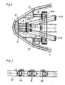
- eine Draufsicht auf ein Schienenfahrzeug mit einer geänderten Stoßverzehrelementeinrichtung und
- Figur 3:
- eine Frontansicht auf eine Stoßverzehrelementeinrichtung nachFigur 1 oder 2.
- Figure 1:
- the head part of a high-speed rail vehicle with a shock absorbing element device in a perspective longitudinal section,
- Figure 2:
- a plan view of a rail vehicle with a modified shock absorbing device and
- Figure 3:
- a front view of a shock absorbing element device according to figure 1 or 2.
Der Kopfteil eines Wagenkastens 1 eines Hochgeschwindigkeits-Schienenfahrzeuges
weist einen Fensterausschnitt 2 im Bereich eines Führerstandes auf und läuft stirnseitig in
einer aerodynamisch gestalteten, im Querschnitt V- oder U-förmig nach Art einer
Flugzeugnase ausgeformten Stirnwand 3 vor dem Fenster 2 des Führerstandes aus.
Zentral in der Wagenkastenlängsmitte befindet sich im Bereich der Stirnwand 3 eine
Kuppeleinrichtung 4, die eine mechanische Kupplung mit anderen Wagenkästen oder
Zugeinrichtungen nach Abnahme oder seitlichem Wegschwenken einer Frontpartie 5 der
Stirnwand 3 zugänglich ist. Oberhalb der Kuppeleinrichtung 4 befindet sich auf einer
Quertraverse 6 vor dem Führerstand eine Stoßverzehrelementeinrichtung 7, díe im
Unglücksfall Stoßkräfte vom Führerstand fernhält. In einer auch die Kuppeleinrichtung 4
aufnehmenden Ebene befinden sich beidseitig der Kuppeleinrichtung 4 im Bereich der bei
Schienenfahrzeugen üblichen Pufferanordnung weitere Stoßverzehrelementeinrichtungen
8, die in Höhe der Kuppeleinrichtung 4 auftretende Stoßkräfte auffängt.The head part of a
Damit auf den Schienen oder zwischen denselben liegende Hindernisse zu keiner
Beschädigung betriebswichtiger Teile des Wagenkastens oder des denselben tragenden
Fahrwerkes führen, sind in einer Ebene unterhalb der Kuppeleinrichtung 4 mehrere
parallel zueinanderstehende einzelne Stoßverzehrelemente 9 bzw. 10 vorgesehen, die
symmetrisch zur senkrechten Mittelebene des Wagenkastens 1 angeordnet sind. Dabei
sind die Stoßverzehrelementeinrichtungen 7,8,9,10 jeweils in spiegelbildlicher Anordnung
auch in der in Figur 1 nicht dargestellten zweiten Hälfte des Wagenkastens 1 vorgesehen.
Die Stoßverzehrelementeinrichtungen 7,8,9,10 bestehen dabei vorzugsweise aus
rohrförmig gestalteten, mit Glas-, Kohle- oder dergleichen Fasern, verstärkten
Kunststoffhülsen und erstrecken sich im wesentlichen über die gesamte axiale Länge der
Stoßverzehrelementeinrichtungen. So that there are no obstacles on the rails or between them
Damage to parts of the body or parts of the body that are essential to its operation
Lead chassis, are in a level below the
Die als Unterfahrschutz vorgesehenen vier einzelnen Stoßverzehrelemente 9,10 sind in
einer waagerechten Ebene nebeneinander angeordnet. Dabei weisen die beiden der
Wagenkasten-Längsmitte benachbarten Stoßverzehrelemente 9 einen kleineren
gegenseitigen axialen Abstand auf, als er zwischen einem dieser mittleren
Stoßverzehrelemente 9 und dem benachbarten äußeren Stoßverzehrelement 10 gegeben
ist. Die freien stirnseitigen Enden der mittleren Stoßverzehrelemente 9 liegen dabei axial
vor den freien Enden der äußeren Stoßverzehrelemente 10. An den mittleren, in
Fahrtrichtung vorstehenden Stoßverzehrelementen 9 werden dadurch über den
befahrenen Schienen querliegende Bäume und dergleichen Hindernisse zunächst
gebrochen und anschließend nach dem Knicken durch die axial zurückgesetzten äußeren
Stoßverzehrelemente vom Gleiskörper weg nach außen aus dem Bewegungsbereich des
Wagenkastens 1 bzw.Fahrwerks herausgeschleudert. Treten dabei Kräfte auf, die ein
bestimmtes Maß überschreiten, verformen sich die Stoßverzehrelemente unter Aufnahme
von mechanischer Energie bleibend, so daß die auf den Wagenkasten übertragenen
Stoßkräfte entsprechend vermindert werden.The four individual
Die einzelnen, im wesentlichen zylindrisch ausgebildeten, Stoßverzehreiemente 9,10
sitzen gemäß Figur 1 an einem gemeinsamen Träger 11, der nach Art eines liegenden U
oder V ausgebildet ist, wobei die beiden benachbart zur Längsmitte des Wagenkastens 1
angeordneten Stoßverzehrelemente 9 am in Fahrtrichtung nach vorn weisenden
verbindungsseitigen Ende 11.1 der geneigt zueinander stehenden Schenkel 11.2 des
Trägers befestigt sind. Die äußeren Stoßverzehrelemente 10 sitzen dagegen auf quer zur
Wagenkastenlängsachse gegenüber den Schenkeln 11.2 abgeknickten Endabschnitten
des Trägers 11. Die Stoßverzehrelementeinrichtung bildet so eine Baueinheit, die für sich
am Wagenkasten oder dessen Untergestell festgesetzt werden kann.The individual, essentially cylindrical,
Gemäß der Ausführungsform nach Figur 2 sitzen bei sonst gleicher Ausbildung die
mittleren Stoßverzehrelemente 9 auf einem eigenen V- bzw.U-förmigen Teilträger 11.3,
während die äußeren Stoßverzehrelemente 10 auf einem eigenständigen Teilträger 11.4
festgesetzt sind. Die den Stoßverzehrelementen 9 abgewandten freien Enden 11.5 des
Teilträgers 11.3 sind dabei in einer Querebene des Wagenkastens 1 festgesetzt, die tiefer
zur Wagenkastenmitte hin versetzt ist, als die Querebene, in welcher der Teilträger 11.4
für die äußeren Stoßverzehrelemente 10 am Wagenkasten 1 bzw. dessen Untergestell
oder einem geeigneten Halter daran festgesetzt ist.According to the embodiment of Figure 2 sit with otherwise the same training
middle shock-absorbing
Durch die Ausbildung der Träger 11 mit den Stoßverzehrelementen 9,10 gemäß den Fig.
2 oder 3 wird ein ggf. eingeleitetes Moment, das diese Unterfahrschutzeinrichtung nach
unten wegdrücken könnte, sicher aufgenommen.By forming the
Figur 3 zeigt eine Frontansicht auf die Anordnung der einzelnen Stoßverzehrelemente 9
und 10 in einer horizontalen Ebene nebeneinander am Träger 11. Dabei sind zur
Verbesserung der Krafteinleitung im Kollisionsfall auf die freien Enden der
Stoßverzehrelemente 7,8,9,10 jeweils platte Prallplatten 12 aufgesetzt.FIG. 3 shows a front view of the arrangement of the individual
Aus Figur 1 ist im übrigen auch zu ersehen, daß die dem Unterfahrschutz dienenden
Stoßverzehrelemente 9,10 unterhalb der nach Art einer Nase ausgewölbten Stirnwand 3
des Wagenkastens sitzen und dabei von einer stromlinienförmig gestalteten, V-förmigen
Schürze verkleidet sind, die der pfeilförmigen Anordnung der Stoßverzehrelemente 9,10
folgend nach Art einer Hüllkurve V-förmig ausgeformt ist. Dabei kann die in Fahrtrichtung
nach vorn weisende Spitze der Hüllkurve als Schneide ausgebildet sein, die weniger
widerstandsfähige Körper ohne Beanspruchung der Stoßverzehrelemente trennt und aus
dem Fahrraum des Schienenfahrzeugs nach außen befördert.It can also be seen from FIG. 1 that those serving as underrun protection
Claims (15)
- Rail vehicle with a vehicle body, to the end of which are centrally attached a coupling device and one or more shock absorber element units facing towards the end face of the vehicle body and having one or more permanently deformable support elements, characterized in that several separate shock absorber elements (9,10) are provided, arranged parallel to one another and symmetrical to the vertical centre plane of the vehicle body (1), below a horizontal plane accommodating the coupling device (4).
- Rail vehicle according to claim 1, characterized in that four individual shock absorber elements (9,10) are arranged next to one another in a horizontal plane.
- Rail vehicle according to claim 1 or 2, characterized in that two of the shock absorber elements (9) adjacent to the vehicle body longitudinal centre extend axially towards the front end of the vehicle body (1) beyond a shock absorber element (10) mounted in each case offset towards the vehicle body side wall.
- Rail vehicle according to claim 1 or any of the following, characterized in that the free ends of the shock absorber elements (9,10) are axially set back towards the vehicle body longitudinal centre relative to the free end of the coupling device (4).
- Rail vehicle according to claim 1 or any of the following, characterized in that the shock absorber elements (9, 10) have flat, dimensionally stable baffle plates (12) on their free end faces.
- Rail vehicle according to claim 5, characterized in that the baffle plates (12) extend radially beyond the cross-sectional surface of the support elements (9, 10).
- Rail vehicle according to claim 1 or any of the following, characterized in that two shock absorber elements (9) mounted adjacent to the longitudinal centre of the vehicle body (1) are fastened together to the connection-side end (11.1) of the limb (11.2) of a U- or V-shaped rigid support (11), the free limb ends of which are fixed to the vehicle body (1).
- Rail vehicle according to claim 1 or any of the following, characterized in that the central shock absorber elements (9) are supported on the underframe at a point more towards the longitudinal centre of the vehicle body (1) than the associated adjacent outer shock absorber elements (10).
- Rail vehicle according to one or more of claims 1 to 7, characterized in that the individual shock absorber elements (9, 10) are supported on a common support (11) on the underframe.
- Rail vehicle according to claim 1 or any of the following, characterized in that the horizontal centre distance between the central shock absorber elements (9) is less than that between one of the central shock absorber elements and the adjacent outer shock absorber element (10).
- Rail vehicle according to claim 1 or any of the following, characterized in that the front wall (3) of the vehicle body (1) containing the flat area holding the shock absorber elements (9,10) is V-shaped in the manner of a generating curve, corresponding to the free end points of the shock absorber elements (9, 10).
- Rail vehicle according to claim 1 or any of the following, characterized in that the support elements of the shock absorber elements (9, 10) are tubular sleeves of glass-fibre-reinforced plastic.
- Rail vehicle according to claim 1 or any of the following, characterized in that several shock absorber elements (7) arranged parallel to one another in the direction of the vehicle body axis are mounted on a horizontal plane above the coupling device (4).
- Rail vehicle according to claim 1 or any of the following, characterized in that every 2 adjacent shock absorber elements (7) have a common baffle plate (12) at their end faces.
- Rail vehicle according to claim 1 or any of the following, characterized in that at least one shock absorber element (8) is mounted on a horizontal plane alongside the coupling device (4).
Applications Claiming Priority (3)
| Application Number | Priority Date | Filing Date | Title |
|---|---|---|---|
| DE19720329 | 1997-05-15 | ||
| DE19720329A DE19720329C1 (en) | 1997-05-15 | 1997-05-15 | Rail vehicle with shock absorbing element device |
| PCT/EP1998/002523 WO1998051555A1 (en) | 1997-05-15 | 1998-04-29 | Rail vehicle with an impact absorbing device |
Publications (2)
| Publication Number | Publication Date |
|---|---|
| EP0923481A1 EP0923481A1 (en) | 1999-06-23 |
| EP0923481B1 true EP0923481B1 (en) | 2001-04-11 |
Family
ID=7829510
Family Applications (1)
| Application Number | Title | Priority Date | Filing Date |
|---|---|---|---|
| EP98924239A Expired - Lifetime EP0923481B1 (en) | 1997-05-15 | 1998-04-29 | Rail vehicle with an impact absorbing device |
Country Status (14)
| Country | Link |
|---|---|
| US (1) | US6167815B1 (en) |
| EP (1) | EP0923481B1 (en) |
| JP (1) | JP3184538B2 (en) |
| KR (1) | KR100323044B1 (en) |
| AT (1) | ATE200452T1 (en) |
| AU (1) | AU713268B2 (en) |
| CA (1) | CA2260901C (en) |
| CZ (1) | CZ285538B6 (en) |
| DE (2) | DE19720329C1 (en) |
| ES (1) | ES2156032T3 (en) |
| HR (1) | HRP980262B1 (en) |
| IL (1) | IL128024A (en) |
| PL (1) | PL330196A1 (en) |
| WO (1) | WO1998051555A1 (en) |
Families Citing this family (34)
| Publication number | Priority date | Publication date | Assignee | Title |
|---|---|---|---|---|
| DE19817861C2 (en) * | 1998-04-22 | 2001-09-06 | Dwa Deutsche Waggonbau Gmbh | Collision protection device for rail vehicles |
| ES2275706T3 (en) * | 2000-08-28 | 2007-06-16 | Mitsubishi Heavy Industries, Ltd. | BODY STRUCTURE. |
| JP3848821B2 (en) * | 2000-08-28 | 2006-11-22 | 三菱重工業株式会社 | Body structure |
| FR2818224B1 (en) * | 2000-12-18 | 2003-01-24 | Alstom | RAIL VEHICLE WITH DRIVING CABIN COMPRISING AN ENERGY ABSORBING STRUCTURE SUITABLE FOR COLLISION ABOVE THE VEHICLE CHASSIS |
| JP3512753B2 (en) * | 2001-04-20 | 2004-03-31 | 川崎重工業株式会社 | Railcar collision energy absorption structure |
| JP4912559B2 (en) * | 2002-09-11 | 2012-04-11 | 株式会社日立製作所 | Rail vehicle |
| DE60327991D1 (en) * | 2003-04-19 | 2009-07-30 | Kawasaki Heavy Ind Ltd | Support structure of the wrecker of a rail vehicle |
| DE10321238B4 (en) * | 2003-05-12 | 2014-08-07 | Siemens Aktiengesellschaft | Rail vehicle with nose cone |
| DE602004009942T2 (en) * | 2003-09-19 | 2008-10-16 | Siemens Transportation Systems Inc., Sacramento | INTEGRATED IMPACT PROTECTION SYSTEM |
| FR2879549B1 (en) * | 2004-12-22 | 2007-02-09 | Alstom Transport Sa | SHOCK ABSORBER DEVICE FOR RAILWAY VEHICLE |
| JP4943905B2 (en) * | 2006-05-10 | 2012-05-30 | 株式会社日立製作所 | Collision energy absorbing device and rail vehicle equipped with the same |
| EP1873036B1 (en) * | 2006-05-10 | 2012-02-22 | Hitachi, Ltd. | Collision energy absorbing device and railway vehicle comprising such a device |
| JP4712604B2 (en) * | 2006-05-10 | 2011-06-29 | 株式会社日立製作所 | Transport equipment |
| JP4845688B2 (en) * | 2006-11-21 | 2011-12-28 | 株式会社日立製作所 | vehicle |
| JP5089277B2 (en) * | 2007-07-18 | 2012-12-05 | 株式会社日立製作所 | Rail vehicle equipped with an obstacle device |
| PL2188165T3 (en) * | 2007-09-11 | 2012-04-30 | Voith Patent Gmbh | Shock absorber |
| DE502008001516D1 (en) * | 2008-01-10 | 2010-11-25 | Alstom Transport Sa | Rail vehicle with multi-stage shock-absorbing device |
| WO2010029188A1 (en) * | 2008-09-15 | 2010-03-18 | Voith Patent Gmbh | Vehicle front-end for mounting to the front face of a track-bound vehicle, in particular a rail vehicle |
| EP2412599B1 (en) * | 2009-03-25 | 2017-06-07 | West Japan Railway Company | Railcar |
| US8839722B2 (en) * | 2010-09-20 | 2014-09-23 | Bombardier Transportation Gmbh | Lightweight compound cab structure for a rail vehicle |
| CN102514588A (en) * | 2011-12-16 | 2012-06-27 | 唐山轨道客车有限责任公司 | Troubleshooting and energy absorbing device and leading car of motor train unit |
| WO2013111315A1 (en) * | 2012-01-27 | 2013-08-01 | 日本車輌製造株式会社 | Railway vehicle |
| CN102661347A (en) * | 2012-05-10 | 2012-09-12 | 上海理工大学 | Impact damper |
| DE102012014328A1 (en) * | 2012-07-12 | 2014-05-15 | Fraunhofer-Gesellschaft zur Förderung der angewandten Forschung e.V. | Deformation element for use as energy absorbing element for rail vehicle, has hollow profile section with polygonal cross-section, where outer edge of hollow profile section extending in longitudinal direction has triangular bent shape |
| WO2015092832A1 (en) * | 2013-12-18 | 2015-06-25 | 川崎重工業株式会社 | Collision energy absorption device for railway vehicle |
| EP3130521B1 (en) * | 2014-04-10 | 2020-09-30 | Hitachi, Ltd. | Cowcatcher and railroad vehicle provided with cowcatcher |
| DE102014209563A1 (en) * | 2014-05-20 | 2015-11-26 | Zf Friedrichshafen Ag | Impact absorbers, in particular for a rail vehicle |
| US9889864B2 (en) * | 2014-12-15 | 2018-02-13 | Crrc Qingdao Sifang Co., Ltd. | Railway vehicle and head vehicle barrier-removing device thereof |
| JP6698283B2 (en) * | 2015-06-03 | 2020-05-27 | 川崎重工業株式会社 | Railway car body |
| CN106114547B (en) * | 2016-06-28 | 2018-10-02 | 中车唐山机车车辆有限公司 | Energy absorption device and rail vehicle |
| EP3560787B1 (en) * | 2018-04-27 | 2024-04-17 | ALSTOM Holdings | Rail vehicle |
| DE102018110243A1 (en) * | 2018-04-27 | 2019-10-31 | Bombardier Transportation Gmbh | RAIL VEHICLE |
| DE102018114245A1 (en) * | 2018-06-14 | 2019-12-19 | Voith Patent Gmbh | Schienenfahrzeugbugnase |
| FR3140605A1 (en) * | 2022-10-11 | 2024-04-12 | Alstom Holdings | Rail vehicle body and associated vehicle |
Family Cites Families (8)
| Publication number | Priority date | Publication date | Assignee | Title |
|---|---|---|---|---|
| US596227A (en) * | 1897-12-28 | The union trust | ||
| DE635018C (en) * | 1933-01-14 | 1936-09-14 | Curt Stedefeld Dipl Ing | Streamlined head part with a rear-mounted driver's cab structure for high-speed railcars |
| FR2238341A5 (en) * | 1973-07-19 | 1975-02-14 | Alsthom | Bellows type vehicle shock absorber - shape of individual elements maintained between given limits |
| FI55632C (en) * | 1978-03-20 | 1979-09-10 | Turunen Pekka J | SAEKERHETSBUFFERT FOER SPAORBUNDEN TRAFIK |
| DE3228941A1 (en) * | 1982-08-03 | 1984-02-09 | Scharfenbergkupplung Gmbh, 3320 Salzgitter | DEVICE ADJUSTING A MEDIUM BUFFER CLUTCH TO RECEIVE Oversized Shocks |
| DE3228942A1 (en) * | 1982-08-03 | 1984-02-09 | Scharfenbergkupplung Gmbh, 3320 Salzgitter | Anti-climbing protection for rail vehicles |
| US4715292A (en) * | 1985-09-13 | 1987-12-29 | Pavlick Michael J | Head end vehicle with crew accommodations with locomotive and other controls |
| FR2712950B1 (en) | 1993-11-25 | 1995-12-29 | Gec Alsthom Transport Sa | Shock absorbing devices and method, frame and vehicle comprising such shock absorbing devices. |
-
1997
- 1997-05-15 DE DE19720329A patent/DE19720329C1/en not_active Expired - Fee Related
-
1998
- 1998-04-29 CA CA002260901A patent/CA2260901C/en not_active Expired - Fee Related
- 1998-04-29 IL IL12802498A patent/IL128024A/en not_active IP Right Cessation
- 1998-04-29 AU AU76505/98A patent/AU713268B2/en not_active Ceased
- 1998-04-29 JP JP54873598A patent/JP3184538B2/en not_active Expired - Fee Related
- 1998-04-29 US US09/214,857 patent/US6167815B1/en not_active Expired - Lifetime
- 1998-04-29 PL PL98330196A patent/PL330196A1/en unknown
- 1998-04-29 DE DE59800618T patent/DE59800618D1/en not_active Expired - Lifetime
- 1998-04-29 WO PCT/EP1998/002523 patent/WO1998051555A1/en active IP Right Grant
- 1998-04-29 EP EP98924239A patent/EP0923481B1/en not_active Expired - Lifetime
- 1998-04-29 KR KR1019997000282A patent/KR100323044B1/en not_active IP Right Cessation
- 1998-04-29 ES ES98924239T patent/ES2156032T3/en not_active Expired - Lifetime
- 1998-04-29 AT AT98924239T patent/ATE200452T1/en active
- 1998-04-29 CZ CZ983498A patent/CZ285538B6/en not_active IP Right Cessation
- 1998-05-14 HR HR980262A patent/HRP980262B1/en not_active IP Right Cessation
Also Published As
| Publication number | Publication date |
|---|---|
| DE59800618D1 (en) | 2001-05-17 |
| JP3184538B2 (en) | 2001-07-09 |
| HRP980262A2 (en) | 1999-02-28 |
| IL128024A (en) | 2002-03-10 |
| CZ285538B6 (en) | 1999-08-11 |
| WO1998051555A1 (en) | 1998-11-19 |
| US6167815B1 (en) | 2001-01-02 |
| ES2156032T3 (en) | 2001-06-01 |
| CA2260901A1 (en) | 1998-11-19 |
| AU713268B2 (en) | 1999-11-25 |
| HRP980262B1 (en) | 2001-10-31 |
| CZ349898A3 (en) | 1999-03-17 |
| IL128024A0 (en) | 1999-11-30 |
| EP0923481A1 (en) | 1999-06-23 |
| ATE200452T1 (en) | 2001-04-15 |
| AU7650598A (en) | 1998-12-08 |
| DE19720329C1 (en) | 1998-11-05 |
| PL330196A1 (en) | 1999-04-26 |
| CA2260901C (en) | 2002-06-11 |
| JP2000506473A (en) | 2000-05-30 |
| KR20000023798A (en) | 2000-04-25 |
| KR100323044B1 (en) | 2002-02-09 |
Similar Documents
| Publication | Publication Date | Title |
|---|---|---|
| EP0923481B1 (en) | Rail vehicle with an impact absorbing device | |
| DE2845548C2 (en) | ||
| DE19510763C2 (en) | Vehicle body with a mounting frame | |
| DE19812701B4 (en) | Body structure for the front of a motor vehicle | |
| EP1232083B1 (en) | Rail vehicle for passenger transportation, especially for local traffic | |
| DE3925990A1 (en) | ASSEMBLY FOR THE FRONT AND REAR AREAS OF A MOTOR VEHICLE | |
| DE19654571A1 (en) | Drive support device for vehicles | |
| DE1680029C3 (en) | Safety framework for a motor vehicle | |
| DE60013632T2 (en) | VEHICLE, IN PARTICULAR Passenger cars, WITH BOX STRUCTURE AGAINST CLIMBING BUMPER | |
| EP0612647A1 (en) | Device for protection for passengers from injuries during a collision of railway trains | |
| EP1582428A1 (en) | Body shell of a railway vehicle, comprising an impact energy absorbing device | |
| DE4230722B4 (en) | Motor vehicle front end with a rigid subframe | |
| DE1605830C3 (en) | Equipment on rail vehicles for clearing away obstacles | |
| DE19712902C1 (en) | Cockpit cross-member in motor vehicle | |
| DE2043524A1 (en) | Front assembly with radiator for motor vehicles | |
| EP1070791B1 (en) | Track cleaner | |
| DE19844707B4 (en) | Traction vehicle, in particular railway high-speed locomotive | |
| DE4119640A1 (en) | Energy absorbing bumper for car - uses ribs which engage tube shaped carrier | |
| DE3827281C2 (en) | ||
| EP0858937B1 (en) | Device for absorbing extreme buffering shock energy for railway vehicles | |
| EP1022211A1 (en) | Sub-frame for mounting suspension | |
| DE19823010A1 (en) | Rail vehicle, especially for local traffic | |
| DE3444303A1 (en) | RAIL VEHICLE, ESPECIALLY LONG GOOD WAGON, WITH TWO WHEEL SETS | |
| DE4440426A1 (en) | Rail vehicle subframe with longitudinal and transverse beams | |
| EP0235635B1 (en) | Beam member for the front end of a vehicle |
Legal Events
| Date | Code | Title | Description |
|---|---|---|---|
| PUAI | Public reference made under article 153(3) epc to a published international application that has entered the european phase |
Free format text: ORIGINAL CODE: 0009012 |
|
| 17P | Request for examination filed |
Effective date: 19981030 |
|
| AK | Designated contracting states |
Kind code of ref document: A1 Designated state(s): AT BE CH DE ES FI FR GB IT LI NL |
|
| RAP1 | Party data changed (applicant data changed or rights of an application transferred) |
Owner name: DAIMLERCHRYSLER AG |
|
| GRAG | Despatch of communication of intention to grant |
Free format text: ORIGINAL CODE: EPIDOS AGRA |
|
| GRAG | Despatch of communication of intention to grant |
Free format text: ORIGINAL CODE: EPIDOS AGRA |
|
| GRAH | Despatch of communication of intention to grant a patent |
Free format text: ORIGINAL CODE: EPIDOS IGRA |
|
| 17Q | First examination report despatched |
Effective date: 20000922 |
|
| GRAH | Despatch of communication of intention to grant a patent |
Free format text: ORIGINAL CODE: EPIDOS IGRA |
|
| GRAA | (expected) grant |
Free format text: ORIGINAL CODE: 0009210 |
|
| AK | Designated contracting states |
Kind code of ref document: B1 Designated state(s): AT BE CH DE ES FI FR GB IT LI NL |
|
| RAP1 | Party data changed (applicant data changed or rights of an application transferred) |
Owner name: DAIMLERCHRYSLER RAIL SYSTEMS GMBH |
|
| REF | Corresponds to: |
Ref document number: 200452 Country of ref document: AT Date of ref document: 20010415 Kind code of ref document: T |
|
| REG | Reference to a national code |
Ref country code: CH Ref legal event code: NV Representative=s name: ROTTMANN, ZIMMERMANN + PARTNER AG Ref country code: CH Ref legal event code: EP |
|
| REF | Corresponds to: |
Ref document number: 59800618 Country of ref document: DE Date of ref document: 20010517 |
|
| ET | Fr: translation filed | ||
| REG | Reference to a national code |
Ref country code: ES Ref legal event code: FG2A Ref document number: 2156032 Country of ref document: ES Kind code of ref document: T3 |
|
| GBT | Gb: translation of ep patent filed (gb section 77(6)(a)/1977) |
Effective date: 20010511 |
|
| ITF | It: translation for a ep patent filed |
Owner name: STUDIO JAUMANN P. & C. S.N.C. |
|
| REG | Reference to a national code |
Ref country code: GB Ref legal event code: IF02 |
|
| PLBI | Opposition filed |
Free format text: ORIGINAL CODE: 0009260 |
|
| PLBF | Reply of patent proprietor to notice(s) of opposition |
Free format text: ORIGINAL CODE: EPIDOS OBSO |
|
| 26 | Opposition filed |
Opponent name: SIEMENS AG CT IP TS Effective date: 20020110 |
|
| NLR1 | Nl: opposition has been filed with the epo |
Opponent name: SIEMENS AG CT IP TS |
|
| PLBF | Reply of patent proprietor to notice(s) of opposition |
Free format text: ORIGINAL CODE: EPIDOS OBSO |
|
| PLBF | Reply of patent proprietor to notice(s) of opposition |
Free format text: ORIGINAL CODE: EPIDOS OBSO |
|
| PLCK | Communication despatched that opposition was rejected |
Free format text: ORIGINAL CODE: EPIDOSNREJ1 |
|
| APBP | Date of receipt of notice of appeal recorded |
Free format text: ORIGINAL CODE: EPIDOSNNOA2O |
|
| APBQ | Date of receipt of statement of grounds of appeal recorded |
Free format text: ORIGINAL CODE: EPIDOSNNOA3O |
|
| APAA | Appeal reference recorded |
Free format text: ORIGINAL CODE: EPIDOS REFN |
|
| APAH | Appeal reference modified |
Free format text: ORIGINAL CODE: EPIDOSCREFNO |
|
| APBU | Appeal procedure closed |
Free format text: ORIGINAL CODE: EPIDOSNNOA9O |
|
| PLBN | Opposition rejected |
Free format text: ORIGINAL CODE: 0009273 |
|
| STAA | Information on the status of an ep patent application or granted ep patent |
Free format text: STATUS: OPPOSITION REJECTED |
|
| 27O | Opposition rejected |
Effective date: 20060704 |
|
| NLR2 | Nl: decision of opposition |
Effective date: 20060704 |
|
| REG | Reference to a national code |
Ref country code: CH Ref legal event code: PFA Owner name: BOMBARDIER TRANSPORTATION GMBH Free format text: DAIMLERCHRYSLER RAIL SYSTEMS GMBH#SAATWINKLER DAMM 43#13627 BERLIN (DE) -TRANSFER TO- BOMBARDIER TRANSPORTATION GMBH#SCHOENEBERGER UFER 1#10785 BERLIN (DE) Ref country code: CH Ref legal event code: NV Representative=s name: BUGNION S.A. |
|
| NLS | Nl: assignments of ep-patents |
Owner name: BOMBARDIER TRANSPORTATION GMBH Effective date: 20070323 |
|
| REG | Reference to a national code |
Ref country code: ES Ref legal event code: PC2A |
|
| REG | Reference to a national code |
Ref country code: FR Ref legal event code: CD Ref country code: FR Ref legal event code: CA |
|
| PLAB | Opposition data, opponent's data or that of the opponent's representative modified |
Free format text: ORIGINAL CODE: 0009299OPPO |
|
| PGFP | Annual fee paid to national office [announced via postgrant information from national office to epo] |
Ref country code: BE Payment date: 20120418 Year of fee payment: 15 Ref country code: DE Payment date: 20120420 Year of fee payment: 15 Ref country code: NL Payment date: 20120425 Year of fee payment: 15 Ref country code: CH Payment date: 20120420 Year of fee payment: 15 |
|
| PGFP | Annual fee paid to national office [announced via postgrant information from national office to epo] |
Ref country code: FI Payment date: 20120411 Year of fee payment: 15 Ref country code: FR Payment date: 20120507 Year of fee payment: 15 Ref country code: GB Payment date: 20120419 Year of fee payment: 15 |
|
| PGFP | Annual fee paid to national office [announced via postgrant information from national office to epo] |
Ref country code: IT Payment date: 20120426 Year of fee payment: 15 |
|
| PGFP | Annual fee paid to national office [announced via postgrant information from national office to epo] |
Ref country code: ES Payment date: 20120425 Year of fee payment: 15 |
|
| PGFP | Annual fee paid to national office [announced via postgrant information from national office to epo] |
Ref country code: AT Payment date: 20120411 Year of fee payment: 15 |
|
| BERE | Be: lapsed |
Owner name: *BOMBARDIER TRANSPORTATION G.M.B.H. Effective date: 20130430 |
|
| REG | Reference to a national code |
Ref country code: NL Ref legal event code: V1 Effective date: 20131101 |
|
| REG | Reference to a national code |
Ref country code: CH Ref legal event code: PL |
|
| REG | Reference to a national code |
Ref country code: AT Ref legal event code: MM01 Ref document number: 200452 Country of ref document: AT Kind code of ref document: T Effective date: 20130430 |
|
| GBPC | Gb: european patent ceased through non-payment of renewal fee |
Effective date: 20130429 |
|
| PG25 | Lapsed in a contracting state [announced via postgrant information from national office to epo] |
Ref country code: BE Free format text: LAPSE BECAUSE OF NON-PAYMENT OF DUE FEES Effective date: 20130430 Ref country code: GB Free format text: LAPSE BECAUSE OF NON-PAYMENT OF DUE FEES Effective date: 20130429 Ref country code: DE Free format text: LAPSE BECAUSE OF NON-PAYMENT OF DUE FEES Effective date: 20131101 Ref country code: LI Free format text: LAPSE BECAUSE OF NON-PAYMENT OF DUE FEES Effective date: 20130430 Ref country code: CH Free format text: LAPSE BECAUSE OF NON-PAYMENT OF DUE FEES Effective date: 20130430 Ref country code: AT Free format text: LAPSE BECAUSE OF NON-PAYMENT OF DUE FEES Effective date: 20130430 |
|
| REG | Reference to a national code |
Ref country code: FR Ref legal event code: ST Effective date: 20131231 |
|
| REG | Reference to a national code |
Ref country code: DE Ref legal event code: R119 Ref document number: 59800618 Country of ref document: DE Effective date: 20131101 |
|
| PG25 | Lapsed in a contracting state [announced via postgrant information from national office to epo] |
Ref country code: NL Free format text: LAPSE BECAUSE OF NON-PAYMENT OF DUE FEES Effective date: 20131101 Ref country code: FI Free format text: LAPSE BECAUSE OF NON-PAYMENT OF DUE FEES Effective date: 20130429 Ref country code: FR Free format text: LAPSE BECAUSE OF NON-PAYMENT OF DUE FEES Effective date: 20130430 Ref country code: IT Free format text: LAPSE BECAUSE OF NON-PAYMENT OF DUE FEES Effective date: 20130429 |
|
| REG | Reference to a national code |
Ref country code: ES Ref legal event code: FD2A Effective date: 20140606 |
|
| PG25 | Lapsed in a contracting state [announced via postgrant information from national office to epo] |
Ref country code: ES Free format text: LAPSE BECAUSE OF NON-PAYMENT OF DUE FEES Effective date: 20130430 |