EP0922824A1 - Device for operating an antipanic lock from the outside - Google Patents
Device for operating an antipanic lock from the outside Download PDFInfo
- Publication number
- EP0922824A1 EP0922824A1 EP98122526A EP98122526A EP0922824A1 EP 0922824 A1 EP0922824 A1 EP 0922824A1 EP 98122526 A EP98122526 A EP 98122526A EP 98122526 A EP98122526 A EP 98122526A EP 0922824 A1 EP0922824 A1 EP 0922824A1
- Authority
- EP
- European Patent Office
- Prior art keywords
- tang
- pin
- plate
- case
- output
- Prior art date
- Legal status (The legal status is an assumption and is not a legal conclusion. Google has not performed a legal analysis and makes no representation as to the accuracy of the status listed.)
- Granted
Links
Images


Classifications
-
- E—FIXED CONSTRUCTIONS
- E05—LOCKS; KEYS; WINDOW OR DOOR FITTINGS; SAFES
- E05B—LOCKS; ACCESSORIES THEREFOR; HANDCUFFS
- E05B65/00—Locks or fastenings for special use
- E05B65/10—Locks or fastenings for special use for panic or emergency doors
- E05B65/1046—Panic bars
- E05B65/106—Panic bars pivoting
- E05B65/1066—Panic bars pivoting the pivot axis being substantially parallel to the longitudinal axis of the bar
-
- E—FIXED CONSTRUCTIONS
- E05—LOCKS; KEYS; WINDOW OR DOOR FITTINGS; SAFES
- E05B—LOCKS; ACCESSORIES THEREFOR; HANDCUFFS
- E05B13/00—Devices preventing the key or the handle or both from being used
- E05B13/005—Disconnecting the handle
-
- E—FIXED CONSTRUCTIONS
- E05—LOCKS; KEYS; WINDOW OR DOOR FITTINGS; SAFES
- E05B—LOCKS; ACCESSORIES THEREFOR; HANDCUFFS
- E05B63/00—Locks or fastenings with special structural characteristics
- E05B63/04—Locks or fastenings with special structural characteristics for alternative use on the right-hand or left-hand side of wings
Definitions
- the present invention relates to a device for operating a lock from the outside, particularly a lock which is actuated from the inside by an antipanic bar.
- antipanic locks comprise a latch which protrudes from the stile of the door to engage the respective selvage of the doorjamb and is actuated by a so-called antipanic bar which is articulated to the door so that it can oscillate at right angles thereto.
- a latch operating device comprising a handle and a pin-tumbler cylinder.
- the aim of the present invention is to provide a device for operating a lock from the outside, particularly for a lock which is operated by an antipanic bar, which allows to obviate the above-mentioned drawbacks.
- This aim is achieved with a device whose characteristics are defined in the claims.
- the device comprises a case 1 which is vertically elongated and is composed of a front wall 2 which has a substantially rectangular shape and of two parallel walls 3 and 4 which are mutually connected by rounded walls 5 and 6 which delimit the compartment 7 for containing the elements of the device (see Figure 4).
- the letters A and B also designate the vertical and horizontal directions.
- the cover 12 rests on the bushes 8-11, closes the compartment 7 to the rear and is fixed by screws 13, 14, 15, 16 which are screwed into the bushes 8-11.
- Threaded holes 17 and 18 are formed in the cover 12 and the threaded ends of hexagonal posts 19 and 20 (see Figure 2) for installing the device on a door 21 are screwed in said cover.
- the device is applied to the outer face of the door 21, opposite an antipanic lock 22 installed on the inner face and provided with an operating bar 23.
- the device is fixed to the lock 22 by means of two screws 24 and 25 which pass through the lock 22 and the door 21 and engage threaded holes of the posts 19 and 20.
- the operative connection between the device and the lock 22 is provided by means of a rod 26 which has a square cross-section and which, when rotated by the device, activates the latch 27 of the antipanic lock 22.
- the rod 26 has a side-fit coupling in a complementarily shaped seat 28 of a cylindrical tang 29 which protrudes from the cover 12 through a hole 30 in which it is supported so that it can rotate about the axis C.
- the tang 29 is termed output tang of the device hereinafter (see Figures 3 and 5).
- the tang 29 is provided with a flange 31 which rests on the inner face of the cover 12 and has a pin 32 ( Figure 5) which is eccentric with respect to the rotation axis C.
- the pin 32 engages a U-shaped slot 33 which is formed in a plate 34 which is adjacent to the flange 31.
- the plate 34 (see Figure 6 in particular) has a substantially rectangular shape and is guided in the direction A between the side walls 3 and 4 of the case 1 and above raised portions 35, 36 and 37 which protrude inside the compartment 7.
- a seat 38 ( Figure 5) is formed in the raised portions 35, 36, 37, and a disk 39 can rotate therein; in turn, said disk has a cylindrical internal cavity 40 which is open toward the front wall 2.
- the disk 39 is milled on a plane which is perpendicular to the axis C, so as to have a slot 41 which is shaped like a circular segment and interacts the internal cavity 40.
- a hole 42 is formed in the disk 39, radially to the axis C and on the plane of the slot 41, and lies on the centerline plane of the slot 41 that passes through the axis C.
- a flange 43 (see also Figure 8) is rotatably accommodated in the cavity 40 provided inside the disk 39, and a central stem 44 and a sector 45 protrude from said flange along the axis C.
- the central stem 44 has an end which is rotatably coupled and inserted in a recess of a square tang 46 which is axially rigidly coupled by means of a screw 47 which engages the stem 44.
- the square tang 46 hereinafter termed input tang, is provided with a collar 48 which is rotatably supported in a sleeve 49 which protrudes out of the front wall 2.
- the collar 48 has an external sector 50 in which a recess 51 is provided which is complementary to the sector 45, so as to receive said sector and provide a rotary coupling between the flange 43 and the tang 46.
- a chamber is formed between the central stem 44 and the collar 48 and accommodates a spring 52 which is wound around the central stem 44 and whose opposite ends are folded outward and rest on opposite sides of a tooth 53, which protrudes inward from the sleeve 49, and of a tab 54 which protrudes axially from the collar 48.
- the tooth 53 and the tab 54 have the same angular breadth, so that the ends of the spring 52, by acting on both sides of the tooth 53 and of the tab 54, keep the input tang 46 elastically in a given inactive position.
- a dead hole 56 (see Figures 5 and 8) which is slightly larger in diameter than the hole 42 of the disk 39.
- a pin 57 having the same diameter is slidingly guided in the dead hole 56 and is provided with a spherical head 58 which has the same diameter as the hole 42, so that an annular shoulder 59 remains between the pin 57 and the spherical head 58.
- a spring 60 is accommodated inside the dead hole 56 and actuates the pin 57 into the position in which the shoulder 59 abuts against the edge of the hole 42. In this position, the spherical head 58 engages the hole 42 and therefore rotationally rigidly couples the disk 39 to the flange 43 and therefore to the tang 46.
- the disk 39 has a pin 61 which is eccentric with respect to the rotation axis C and is arranged, in the inactive condition, on the plane D which is perpendicular to the plane A and passes through the axis C.
- the pin 61 engages a slot 62 ( Figure 6) which is formed on a lateral edge of the plate 34 so that the rotation of the disk 39 in one direction or the other produces the movement of the plate 34 in the direction A by an equal extent with respect to the plane D.
- the slot 33 is composed of two portions 63 and 64 which are perpendicular to the plane A and are connected by a circular portion 65 so as to form a slot which is U-shaped and open toward the wall 3 and in which the portions 63 and 64 are equidistant with respect to the plane of the slot 62.
- the pin 32 of the flange 31 of the output tang 29 is engaged in the portion 63 or 64, depending on whether the device must be installed on a right- or left-opening door, as described hereinafter.
- a key 66 is engaged in the slot 41 of the disk 39 and is constituted by a T-shaped plate which is guided along the axis A between the side walls 3 and 4 of the casing 1 and the bushes 10 and 11.
- a pin 67 (see Figure 4) is centrally fixed on the key 66 and a spring 68 is wound thereon; said spring comprises two arms which rest on the bushes 10 and 11 and tend to space the key 66 from the disk 39.
- Two threaded holes 69 and 70 ( Figure 7) are formed in the key 66 below the pin 67 and symmetrically with respect to the plane A.
- a pin 71 is screwed into the hole 69; however, depending on the type of right or left opening of the door, it can be screwed into the hole 70.
- a slider 72 acts against the pin 71 and is movable at right angles to the axis A by means of a pin-tumbler cylinder 73.
- the slider 72 is constituted by a plate in which there are two studs 74 and 75 and a slot 76.
- the two studs 74 and 75 engage in a slot 77 which is formed in the rear face of the wall 2 at right angles to the axis A.
- the slot 76 is crossed by a screw 78 which, together with the studs 74 and 75, guides the slider 72 in a direction which is perpendicular to the axis A.
- the slider 72 has an extension which forms an isosceles-triangle cam 79 in which the oblique sides form two ramps 80 and 81 which converge, from the upper edge 82 and 83 of the slider, toward a flat region or hollow 84 formed at the top of the cam 79.
- a recess 85 is formed in the lower edge of the slider 72 and is adapted to be engaged by the bit 86 of the cylinder 73.
- the cylinder 73 is accommodated in a seat of a body 87 ( Figures 5 and 9) which is applied externally to the front wall 2 and is fixed by means of screws 88 and 89 which are inserted from the inside through the front wall.
- the slider 72 is capable of assuming two stable positions at the right and left stroke limits.
- a hollow 90 ( Figures 5 and 9) which accommodates a cylindrical spring 91 which acts on a ball 92, which can engage one of two holes 93 and 94 formed in the slider 72.
- the operation of the above-described device is the same both when the device is to be installed on a right-opening door, i.e., a door in which the hinges are arranged on the right, and when the door must open to the left, i.e., has hinges arranged on the left.
- the device can be preset so as to operate for just one type of opening.
- the front plate 2 above and below the plate 34, two threaded holes 95 and 96 are provided, and a pin is screwed in each case in one of said holes; said pin, starting from a position in which the slot 62 lies on the axis D, prevents the stroke of the plate 34 in the direction in which the pin is arranged.
- the pin is designated by the reference numeral 97 and is screwed in the hole 96 and therefore allows the plate 34 to move only upward. Accordingly, the disk 39 and the input tang 46 can rotate in the clockwise direction E (viewing the case 1 from the rear).
- the pin 32 of the output tang 29 is arranged so as to engage the portion of the slot that allows the tang 29 to rotate in the same direction as the input tang 46, i.e., the portion 64 as shown in Figure 6.
- the cover 12 in order to indicate on the outside of the case the manner in which the two pins 71 and 97 must be preset according to the door opening direction, in the cover 12 there are four openings 98, 99, 100, 101 (see Figure 3) which allow to position the pins 71 and 97 without having to remove the cover 12 and there are two notches 102 and 103 which allow to orientate a reference 104 of the output tang 29 so that the pin 32 engages the portion 63 or 64 of the slot 65.
- the pin 32 is assumed to be engaged in the portion 64 (see Figure 6).
- the openings 98, 101 allow to place the pins 97 and 71 in the threaded holes 95 and 70 so as to preset the device for right-opening doors.
- the openings 95 and 70 and the notch 102 are identified by a Dx (right) symbol in order to indicate right-side opening.
- the openings 99 and 100 allow to position the pins 97 and 71 for left-opening doors.
- the openings 99, 100 and the notch 103 are identified by the symbol Sx (left) to indicate left-side opening.
- the operating method of the device is as follows.
- the pins 97 and 71 are arranged respectively in the hole 96 of the front wall 2 and in the hole 69 of the key 66, identified by Sx, and the output tang 29 is orientated so as to place the reference 104 on the Sx symbol of the cover. In this position, the pin 32 is engaged in the portion 64 of the slot 33.
- the cylinder 73 In order to deactivate the device, i.e., to prevent the lock 22 from being operated from the outside, the cylinder 73 is operated; its bit 86, by turning in the same direction as the handle 55, i.e. clockwise, acts on the slider 72, moving it into the position in which the pin 71, after moving along the ramp 80 of the cam 79, has risen onto the flat portions 84 ( Figure 7).
- the invention perfectly achieves the intended aim.
- the movement of the pin 32 of the output tang 29 in the upper portion 63 of the slot 33 is performed after removing the pin 97 from the hole 96 and before said pin is screwed into the hole 95.
- the plate 34 can thus slide freely and the pin 32 can move along the arc-like portion 65 of the slot 33 in order to engage in the upper portion 63.
- the pin 32 engages the end of the portion 63 or 64 that lies opposite to the ends joined by the arc-like portion 65, and that the radius of the pivot 32 from the rotation axis C of the output tang 29 is greater than the stroke of the plate 34 up to the abutment against the pin 97. In this manner, the pin 32 cannot oscillate to return to the arc-like portion 65 and remains rigidly coupled to the selected portion 63 or 64 of the plate 34.
Abstract
Description
- The present invention relates to a device for operating a lock from the outside, particularly a lock which is actuated from the inside by an antipanic bar.
- It is known that antipanic locks comprise a latch which protrudes from the stile of the door to engage the respective selvage of the doorjamb and is actuated by a so-called antipanic bar which is articulated to the door so that it can oscillate at right angles thereto.
- On the outer side of the door a latch operating device is provided comprising a handle and a pin-tumbler cylinder.
- Conventional antipanic locks suffer the drawback that the handle of the external operating device is constantly rotationally coupled to the pin that transmits the movement to the latch and therefore the lock is exposed to violent break-in attempts.
- Moreover, conventional operating devices are provided for right-only or left-only installation and it is therefore necessary to have two kinds of device in order to cope with this dual installation requirement.
- The aim of the present invention is to provide a device for operating a lock from the outside, particularly for a lock which is operated by an antipanic bar, which allows to obviate the above-mentioned drawbacks. This aim is achieved with a device whose characteristics are defined in the claims.
- Further characteristics and advantages of the present invention will become apparent from the following detailed description of a preferred embodiment, illustrated by way of non-limitative example in the accompanying drawings, wherein:
- Figure 1 is a perspective view of the device combined with an antipanic lock;
- Figure 2 is a partial sectional view of the device and of the lock in the position for installation on a door;
- Figure 3 is an exploded view of the device;
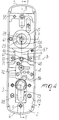
- Figure 4 is a rear view of the device after removing the cover that closes, at the rear, the case that contains the elements of the device;
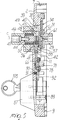
- Figure 5 is a sectional view, taken along the plane V-V of Figure 4;
- Figure 6 is a view, similar to Figure 4, after removing the output tang that drives the square-section rod that operates the antipanic lock;
- Figures 7 and 8 are views of the rear of the device in two operating positions after the removal of the cover, of the tang and of the plate that connects the output tang to the input tang;
- Figure 9 is a view, similar to Figure 5, with some elements shown in cross-section.
-
- With reference to Figures 1 to 5, the device comprises a
case 1 which is vertically elongated and is composed of afront wall 2 which has a substantially rectangular shape and of twoparallel walls rounded walls compartment 7 for containing the elements of the device (see Figure 4). - Four threaded
bushes front wall 2 into thecompartment 7; the first twobushes bushes - For the sake of convenience in description, the letters A and B also designate the vertical and horizontal directions.
- The
cover 12 rests on the bushes 8-11, closes thecompartment 7 to the rear and is fixed byscrews - Threaded
holes 17 and 18 are formed in thecover 12 and the threaded ends ofhexagonal posts 19 and 20 (see Figure 2) for installing the device on adoor 21 are screwed in said cover. The device is applied to the outer face of thedoor 21, opposite anantipanic lock 22 installed on the inner face and provided with anoperating bar 23. The device is fixed to thelock 22 by means of twoscrews lock 22 and thedoor 21 and engage threaded holes of theposts - The operative connection between the device and the
lock 22 is provided by means of arod 26 which has a square cross-section and which, when rotated by the device, activates thelatch 27 of theantipanic lock 22. - The
rod 26 has a side-fit coupling in a complementarilyshaped seat 28 of acylindrical tang 29 which protrudes from thecover 12 through a hole 30 in which it is supported so that it can rotate about the axis C. Thetang 29 is termed output tang of the device hereinafter (see Figures 3 and 5). - The
tang 29 is provided with aflange 31 which rests on the inner face of thecover 12 and has a pin 32 (Figure 5) which is eccentric with respect to the rotation axis C. - The
pin 32 engages a U-shapedslot 33 which is formed in aplate 34 which is adjacent to theflange 31. - The plate 34 (see Figure 6 in particular) has a substantially rectangular shape and is guided in the direction A between the
side walls case 1 and above raisedportions compartment 7. - A seat 38 (Figure 5) is formed in the raised
portions disk 39 can rotate therein; in turn, said disk has a cylindricalinternal cavity 40 which is open toward thefront wall 2. - The
disk 39 is milled on a plane which is perpendicular to the axis C, so as to have aslot 41 which is shaped like a circular segment and interacts theinternal cavity 40. Ahole 42 is formed in thedisk 39, radially to the axis C and on the plane of theslot 41, and lies on the centerline plane of theslot 41 that passes through the axis C. - A flange 43 (see also Figure 8) is rotatably accommodated in the
cavity 40 provided inside thedisk 39, and acentral stem 44 and asector 45 protrude from said flange along the axis C. Thecentral stem 44 has an end which is rotatably coupled and inserted in a recess of asquare tang 46 which is axially rigidly coupled by means of a screw 47 which engages thestem 44. - The
square tang 46, hereinafter termed input tang, is provided with acollar 48 which is rotatably supported in asleeve 49 which protrudes out of thefront wall 2. - The
collar 48 has anexternal sector 50 in which arecess 51 is provided which is complementary to thesector 45, so as to receive said sector and provide a rotary coupling between theflange 43 and thetang 46. - A chamber is formed between the
central stem 44 and thecollar 48 and accommodates aspring 52 which is wound around thecentral stem 44 and whose opposite ends are folded outward and rest on opposite sides of atooth 53, which protrudes inward from thesleeve 49, and of atab 54 which protrudes axially from thecollar 48. Thetooth 53 and thetab 54 have the same angular breadth, so that the ends of thespring 52, by acting on both sides of thetooth 53 and of thetab 54, keep theinput tang 46 elastically in a given inactive position. In this manner, by applying to the tang 46 a handle 55 (Figures 1 and 3) which is orientated for right or left actuation, thespring 52 in any case returns thetang 46 to the inactive position both when thehandle 55 is operated clockwise and when it is operated counterclockwise. - In the
flange 43 there is a dead hole 56 (see Figures 5 and 8) which is slightly larger in diameter than thehole 42 of thedisk 39. Apin 57 having the same diameter is slidingly guided in thedead hole 56 and is provided with aspherical head 58 which has the same diameter as thehole 42, so that anannular shoulder 59 remains between thepin 57 and thespherical head 58. - A
spring 60 is accommodated inside thedead hole 56 and actuates thepin 57 into the position in which theshoulder 59 abuts against the edge of thehole 42. In this position, thespherical head 58 engages thehole 42 and therefore rotationally rigidly couples thedisk 39 to theflange 43 and therefore to thetang 46. - The
disk 39 has apin 61 which is eccentric with respect to the rotation axis C and is arranged, in the inactive condition, on the plane D which is perpendicular to the plane A and passes through the axis C. - The
pin 61 engages a slot 62 (Figure 6) which is formed on a lateral edge of theplate 34 so that the rotation of thedisk 39 in one direction or the other produces the movement of theplate 34 in the direction A by an equal extent with respect to the plane D. - The
slot 33 is composed of twoportions circular portion 65 so as to form a slot which is U-shaped and open toward thewall 3 and in which theportions slot 62. - The
pin 32 of theflange 31 of theoutput tang 29 is engaged in theportion - A
key 66 is engaged in theslot 41 of thedisk 39 and is constituted by a T-shaped plate which is guided along the axis A between theside walls casing 1 and thebushes - A pin 67 (see Figure 4) is centrally fixed on the
key 66 and aspring 68 is wound thereon; said spring comprises two arms which rest on thebushes key 66 from thedisk 39. Two threadedholes 69 and 70 (Figure 7) are formed in thekey 66 below thepin 67 and symmetrically with respect to the plane A. Apin 71 is screwed into thehole 69; however, depending on the type of right or left opening of the door, it can be screwed into thehole 70. - A
slider 72 acts against thepin 71 and is movable at right angles to the axis A by means of a pin-tumbler cylinder 73. - The
slider 72 is constituted by a plate in which there are twostuds 74 and 75 and aslot 76. The twostuds 74 and 75 engage in aslot 77 which is formed in the rear face of thewall 2 at right angles to the axis A. Theslot 76 is crossed by ascrew 78 which, together with thestuds 74 and 75, guides theslider 72 in a direction which is perpendicular to the axis A. - At the upward-facing end, the
slider 72 has an extension which forms an isosceles-triangle cam 79 in which the oblique sides form tworamps upper edge - A
recess 85 is formed in the lower edge of theslider 72 and is adapted to be engaged by thebit 86 of thecylinder 73. - The
cylinder 73 is accommodated in a seat of a body 87 (Figures 5 and 9) which is applied externally to thefront wall 2 and is fixed by means ofscrews - The
slider 72 is capable of assuming two stable positions at the right and left stroke limits. For this purpose, in thefront wall 2, above thetransverse slot 77, there is a hollow 90 (Figures 5 and 9) which accommodates acylindrical spring 91 which acts on aball 92, which can engage one of twoholes 93 and 94 formed in theslider 72. - When the
slider 72 abuts against theright wall 4 of thecase 1, as shown in Figures 4, 6 and 8, thepin 69 rests on theupper edge 82 to the side of theramp 80 and theball 92 engages the hole 93. On the other hand, when theslider 72 abuts against theleft wall 3 of the case, as shown in Figure 7, thepin 69 has risen onto the flat region 84 and theball 92 has engaged thehole 94. - The operation of the above-described device is the same both when the device is to be installed on a right-opening door, i.e., a door in which the hinges are arranged on the right, and when the door must open to the left, i.e., has hinges arranged on the left.
- However, according to a substantial prerogative of the present invention, the device can be preset so as to operate for just one type of opening. For this purpose, in the
front plate 2, above and below theplate 34, two threadedholes slot 62 lies on the axis D, prevents the stroke of theplate 34 in the direction in which the pin is arranged. In Figures 4 and 6, the pin is designated by thereference numeral 97 and is screwed in thehole 96 and therefore allows theplate 34 to move only upward. Accordingly, thedisk 39 and theinput tang 46 can rotate in the clockwise direction E (viewing thecase 1 from the rear). - Likewise, the
pin 32 of theoutput tang 29 is arranged so as to engage the portion of the slot that allows thetang 29 to rotate in the same direction as theinput tang 46, i.e., theportion 64 as shown in Figure 6. - In order to ensure that the rotation of the
bit 86 also occurs in the direction that corresponds to the door opening or closure side, thepin 71 is screwed into the corresponding hole of the key 66, which is indeed thehole 69, as shown in Figures 4, 6 and 8. - Advantageously, in order to indicate on the outside of the case the manner in which the two
pins cover 12 there are fouropenings pins cover 12 and there are twonotches reference 104 of theoutput tang 29 so that thepin 32 engages theportion slot 65. In the illustrated example, thepin 32 is assumed to be engaged in the portion 64 (see Figure 6). - The
openings pins holes openings notch 102 are identified by a Dx (right) symbol in order to indicate right-side opening. - Likewise, the
openings pins openings notch 103 are identified by the symbol Sx (left) to indicate left-side opening. - The operating method of the device is as follows.
- Assuming that a left-opening door has to be opened (as shown in the Figures), the
pins hole 96 of thefront wall 2 and in thehole 69 of the key 66, identified by Sx, and theoutput tang 29 is orientated so as to place thereference 104 on the Sx symbol of the cover. In this position, thepin 32 is engaged in theportion 64 of theslot 33. - By operating the
handle 55 in the clockwise direction E, by means of the coupling provided by thepin 57 between thedisk 39 and theflange 43, thepin 61 of thedisk 39 moves upward, drawing theplate 34 and thepin 32 with it and therefore turning theoutput tang 29 in the same direction E. Theoutput tang 29 turns thesquare rod 26 that is coupled thereto with a side fit and which, by acting on theinternal lock 22, releases thelatch 27, thus allowing to open the door from the outside. - The rotation of the
input tang 46 loads thespring 52, which as soon as the action on thehandle 55 ceases returns said handle to the inactive position. - In order to deactivate the device, i.e., to prevent the
lock 22 from being operated from the outside, thecylinder 73 is operated; itsbit 86, by turning in the same direction as thehandle 55, i.e. clockwise, acts on theslider 72, moving it into the position in which thepin 71, after moving along theramp 80 of the cam 79, has risen onto the flat portions 84 (Figure 7). - As a consequence of the movement of the
slider 72, the key 66 is raised by an extent which places thepin 57 fully inside thedead hole 56 and accordingly disengages thedisk 39 from theflange 43. With this uncoupling it is no longer possible to transmit the action of thehandle 55, by means of the rotation of theinput tang 46, to thedisk 39 and therefore theoutput tang 29 does not move. In practice thehandle 55 is merely actuated idly. - It is evident that the invention perfectly achieves the intended aim. In particular, it is noted that in order to preset the device for right-side opening, the movement of the
pin 32 of theoutput tang 29 in theupper portion 63 of theslot 33 is performed after removing thepin 97 from thehole 96 and before said pin is screwed into thehole 95. Theplate 34 can thus slide freely and thepin 32 can move along the arc-like portion 65 of theslot 33 in order to engage in theupper portion 63. - It should be observed that in the inactive position of the device, the
pin 32 engages the end of theportion like portion 65, and that the radius of thepivot 32 from the rotation axis C of theoutput tang 29 is greater than the stroke of theplate 34 up to the abutment against thepin 97. In this manner, thepin 32 cannot oscillate to return to the arc-like portion 65 and remains rigidly coupled to the selectedportion plate 34. - It is particularly noteworthy that the rotation of the
bit 86 and therefore of the key 105 by means of which the device is deactivated matches the direction of the opening of the door. By moving thepin 71 from thehole 69 to theother hole 70, it is in fact possible to lift the key 66 into the position for disengaging theinput tang 46 from theoutput tang 29, moving theslider 72 toward its right or left stroke limit, matching the direction of rotation of thebit 86 of thecylinder 73. - The disclosures in Italian Patent Application No. BO97A000709 from which this application claims priority are incorporated herein by reference.
- Where technical features mentioned in any claim are followed by reference signs, those reference signs have been included for the sole purpose of increasing the intelligibility of the claims and accordingly such reference signs do not have any limiting effect on the interpretation of each element identified by way of example by such reference signs.
Claims (9)
- A device for actuating a lock from the outside, particularly for an internal lock operated by an antipanic bar, characterized in that it comprises a case (1), an input tang (46) and an output tang (29), which are supported so as to be able to rotate coaxially in said case, a rod (26) being rotationally coupled to said output tang (29) and being connected to said internal lock in order to actuate the opening action, an operating handle (55) being rotationally rigidly coupled to said input tang (46), said tangs (46, 29) having adjacent ends between which there is a plate (34) which is guided at right angles to the rotation axis (C) of said tangs and is provided with a first slot (62), which is engaged, on one side of said plate, by an eccentric pin (61) of said input tang (46), and with a second slot (33), which can be engaged, on the opposite side with respect to said plate, by an eccentric pin (32) of said output tang (29), so that by operating the handle (55) and the corresponding input tang (46) in one direction the output tang (29) rotates in the matching direction, an abutment (97) being further provided which can be positioned from the outside of said case and allows to move said plate (34) and therefore to rotate the handle and the output tang (29) only in the direction that matches the door opening direction.
- The device according to claim 1, characterized in that said second slot (33) is U-shaped, with two portions (63, 64) which are mutually parallel and perpendicular to the sliding direction (A) of said plate and are connected by a portion (65) which is shaped like a circular arc, said parallel portions being individually engageable by the eccentric pin (32) of said output tang (29) so as to match the direction of rotation of said tang.
- The device according to claim 1 or 2, characterized in that said input tang (46) comprises a flange (43) whereon a disk (39) is rotatably supported, said disk being provided with said eccentric pin (61), a dead hole (56) being formed radially in said flange in order to accommodate a pin (57) which is actuated by a spring (60) so as to engage in a hole (42) of said disk (39), to produce a rotary coupling between said flange (43) and said disk (39), actuation means (66, 72) being provided which are actuated by the bit (86) of a cylinder (73) which is accommodated in said case (1) and are adapted to act on said pivot (57) in order to uncouple said flange (43) from said disk (39) and make the actuation of the handle ineffective.
- The device according to claim 3, characterized in that said actuation means comprise: a key (66), which is guided in said case between an active position, in which it acts on said pin (57) in order to uncouple said flange (43) from said disk (39), and a passive position; a slider (72) which is guided in said case transversely to said key (66), can be actuated by said bit (86) and is provided with a cam (79) which cooperates with an abutment (71) which is rigidly coupled to said key (66) so that by moving said slider (72) by means of said bit (86) said cam (79), by acting on said abutment (71), produces the movement of said key (72) between said active and passive positions.
- The device according to claim 4, characterized in that said cam (79) comprises two ramps (80, 81) which converge toward a flat portion (84), said abutment (71) being arrangeable in two positions (69, 70) of said key (66) so as to move said key between said passive position and said active position according to the direction of the movement of said slider (72), which corresponds to a rotation of the bit in the same direction as the rotation of the handle.
- A device according to one of the preceding claims, characterized in that said case (1) comprises a closure cover (12) which is provided with openings (98, 99; 100, 101) for selecting the position of the abutment (97) of said plate (34) and of the abutment (71) on said cam (79) so as to match the direction of the opening of said door.
- A device according to claim 6, characterized in that the abutment of said plate (34) is constituted by a pin (97) which can be screwed through respective openings (98, 99) into one of two threaded holes (95, 96) which are formed in said case so as to block the movement of the plate (34) in reverse with respect to the direction that matches the opening direction of said door.
- A device according to claim 6, characterized in that the abutment on said cam (79) is constituted by a pin (71) which can be screwed through respective openings (100, 101) in one of two threaded holes (69, 70) formed in said key (66).
- A device according to one of the preceding claims, characterized in that said input tang (46) for the coupling of said handle (55) has a seat (38) for a torsion spring (52), a tooth (53) being inserted between the ends of said spring, said tooth being rigidly coupled to said case.
Applications Claiming Priority (2)
| Application Number | Priority Date | Filing Date | Title |
|---|---|---|---|
| IT97BO000709A IT1298365B1 (en) | 1997-12-10 | 1997-12-10 | DEVICE FOR COMMANDING FROM THE OUTSIDE OF A PANIC LOCK. |
| ITBO970709 | 1997-12-10 |
Publications (2)
| Publication Number | Publication Date |
|---|---|
| EP0922824A1 true EP0922824A1 (en) | 1999-06-16 |
| EP0922824B1 EP0922824B1 (en) | 2002-06-12 |
Family
ID=11342683
Family Applications (1)
| Application Number | Title | Priority Date | Filing Date |
|---|---|---|---|
| EP98122526A Expired - Lifetime EP0922824B1 (en) | 1997-12-10 | 1998-11-30 | Device for operating an antipanic lock from the outside |
Country Status (4)
| Country | Link |
|---|---|
| EP (1) | EP0922824B1 (en) |
| DE (1) | DE69805942T2 (en) |
| ES (1) | ES2176888T3 (en) |
| IT (1) | IT1298365B1 (en) |
Cited By (4)
| Publication number | Priority date | Publication date | Assignee | Title |
|---|---|---|---|---|
| EP1113131A2 (en) * | 1999-12-31 | 2001-07-04 | Storo Tschierv GmbH | Push-bar for doors in general |
| FR2909701A1 (en) * | 2006-12-08 | 2008-06-13 | Jpm Sas Soc Par Actions Simpli | Semi-assembly type operating device for door, has mobile transmission assembly moving in translation along direction parallel to reference plane, and stop system reversibly deformed between two configurations |
| EP2708688A1 (en) * | 2012-09-13 | 2014-03-19 | ASSA ABLOY Sicherheitstechnik GmbH | Handle bar having a rotational axis at the identical height of the turning handle |
| EP3085862A1 (en) * | 2015-04-21 | 2016-10-26 | Talleres De Escoriaza, S.A. | Multifunction handle for fire doors |
Citations (3)
| Publication number | Priority date | Publication date | Assignee | Title |
|---|---|---|---|---|
| FR2581692A1 (en) * | 1985-05-09 | 1986-11-14 | Emery | Lock for closing and especially for the closing of a door having a pushbar |
| FR2644826A1 (en) * | 1989-03-24 | 1990-09-28 | Chauvat & Sofranq Reunis | Mechanism for operating a lock |
| FR2682985A1 (en) * | 1991-10-28 | 1993-04-30 | Jpm Chauvat Sa | Reversible housing for controlling and disabling an anti-panic lock with pushbar |
-
1997
- 1997-12-10 IT IT97BO000709A patent/IT1298365B1/en active IP Right Grant
-
1998
- 1998-11-30 DE DE69805942T patent/DE69805942T2/en not_active Expired - Lifetime
- 1998-11-30 ES ES98122526T patent/ES2176888T3/en not_active Expired - Lifetime
- 1998-11-30 EP EP98122526A patent/EP0922824B1/en not_active Expired - Lifetime
Patent Citations (3)
| Publication number | Priority date | Publication date | Assignee | Title |
|---|---|---|---|---|
| FR2581692A1 (en) * | 1985-05-09 | 1986-11-14 | Emery | Lock for closing and especially for the closing of a door having a pushbar |
| FR2644826A1 (en) * | 1989-03-24 | 1990-09-28 | Chauvat & Sofranq Reunis | Mechanism for operating a lock |
| FR2682985A1 (en) * | 1991-10-28 | 1993-04-30 | Jpm Chauvat Sa | Reversible housing for controlling and disabling an anti-panic lock with pushbar |
Cited By (8)
| Publication number | Priority date | Publication date | Assignee | Title |
|---|---|---|---|---|
| EP1113131A2 (en) * | 1999-12-31 | 2001-07-04 | Storo Tschierv GmbH | Push-bar for doors in general |
| EP1113131A3 (en) * | 1999-12-31 | 2001-09-26 | Storo Tschierv GmbH | Push-bar for doors in general |
| FR2909701A1 (en) * | 2006-12-08 | 2008-06-13 | Jpm Sas Soc Par Actions Simpli | Semi-assembly type operating device for door, has mobile transmission assembly moving in translation along direction parallel to reference plane, and stop system reversibly deformed between two configurations |
| WO2008084144A2 (en) * | 2006-12-08 | 2008-07-17 | Jpm Sas | Manoeuvring members with protection against hooliganism |
| WO2008084144A3 (en) * | 2006-12-08 | 2008-09-12 | Jpm Sas | Manoeuvring members with protection against hooliganism |
| EP2708688A1 (en) * | 2012-09-13 | 2014-03-19 | ASSA ABLOY Sicherheitstechnik GmbH | Handle bar having a rotational axis at the identical height of the turning handle |
| EP3085862A1 (en) * | 2015-04-21 | 2016-10-26 | Talleres De Escoriaza, S.A. | Multifunction handle for fire doors |
| RU2697341C2 (en) * | 2015-04-21 | 2019-08-14 | Тальерес Де Эскориаса С.А. | Multifunctional handle for exit doors in case of fire |
Also Published As
| Publication number | Publication date |
|---|---|
| ES2176888T3 (en) | 2002-12-01 |
| ITBO970709A1 (en) | 1999-06-10 |
| DE69805942D1 (en) | 2002-07-18 |
| EP0922824B1 (en) | 2002-06-12 |
| IT1298365B1 (en) | 2000-01-05 |
| ITBO970709A0 (en) | 1997-12-10 |
| DE69805942T2 (en) | 2003-02-20 |
Similar Documents
| Publication | Publication Date | Title |
|---|---|---|
| US5713612A (en) | Adjustable interconnected lock assembly with automatic deadbolt | |
| US5794472A (en) | Disconnecting drive mechanism for cylindrical lockset | |
| CA2495523C (en) | Security classroom function lock mechanism | |
| RU2324042C2 (en) | Door blocking mechanism | |
| EP1118739B1 (en) | Lock | |
| US5819562A (en) | Door lock having multiple locking bolts | |
| AU2008344984B2 (en) | Mortice lock with adjustable handing | |
| US20040084909A1 (en) | Single bolt mortise lock | |
| US4107966A (en) | Selectively rotatable cylinder for a lock | |
| EP0535497B1 (en) | Improved lock with an emergency opening device | |
| KR20010071324A (en) | Mortise lock | |
| EP0922824B1 (en) | Device for operating an antipanic lock from the outside | |
| US5570913A (en) | Independent dual deadbolt locking mechanism | |
| GB2271380A (en) | Lock mechanism with deadlocking latchbolt | |
| GB2225607A (en) | Improvements in or relating to locks | |
| US3031876A (en) | Master key controlled permutation locks | |
| US20050126234A1 (en) | Spring latch lock | |
| GB2322902A (en) | Latch and deadbolt locksets | |
| EP0922825B1 (en) | Device for selecting the actuation direction of a lock according to the door side on which it is installed | |
| US4590777A (en) | Doorlock | |
| GB2226358A (en) | Improvements in or relating to handle assemblies | |
| AU2015205976B2 (en) | Improved multiple function door lock mechanism | |
| AU2014339757B2 (en) | Mortice lock assembly for use with cylinder cam in three zones | |
| AU2014339757A1 (en) | Mortice lock assembly for use with cylinder cam in three zones | |
| AU2015275335A1 (en) | Mortice lock with adjustable handing |
Legal Events
| Date | Code | Title | Description |
|---|---|---|---|
| PUAI | Public reference made under article 153(3) epc to a published international application that has entered the european phase |
Free format text: ORIGINAL CODE: 0009012 |
|
| AK | Designated contracting states |
Kind code of ref document: A1 Designated state(s): DE ES FI FR GB IT SE |
|
| AX | Request for extension of the european patent |
Free format text: AL;LT;LV;MK;RO;SI |
|
| 17P | Request for examination filed |
Effective date: 19991124 |
|
| AKX | Designation fees paid |
Free format text: DE ES FI FR GB IT SE |
|
| GRAG | Despatch of communication of intention to grant |
Free format text: ORIGINAL CODE: EPIDOS AGRA |
|
| GRAG | Despatch of communication of intention to grant |
Free format text: ORIGINAL CODE: EPIDOS AGRA |
|
| 17Q | First examination report despatched |
Effective date: 20010730 |
|
| GRAG | Despatch of communication of intention to grant |
Free format text: ORIGINAL CODE: EPIDOS AGRA |
|
| GRAH | Despatch of communication of intention to grant a patent |
Free format text: ORIGINAL CODE: EPIDOS IGRA |
|
| RAP1 | Party data changed (applicant data changed or rights of an application transferred) |
Owner name: CISA S.P.A. |
|
| GRAH | Despatch of communication of intention to grant a patent |
Free format text: ORIGINAL CODE: EPIDOS IGRA |
|
| GRAA | (expected) grant |
Free format text: ORIGINAL CODE: 0009210 |
|
| AK | Designated contracting states |
Kind code of ref document: B1 Designated state(s): DE ES FI FR GB IT SE |
|
| REG | Reference to a national code |
Ref country code: GB Ref legal event code: FG4D |
|
| REF | Corresponds to: |
Ref document number: 69805942 Country of ref document: DE Date of ref document: 20020718 |
|
| ET | Fr: translation filed | ||
| REG | Reference to a national code |
Ref country code: ES Ref legal event code: FG2A Ref document number: 2176888 Country of ref document: ES Kind code of ref document: T3 |
|
| PLBE | No opposition filed within time limit |
Free format text: ORIGINAL CODE: 0009261 |
|
| STAA | Information on the status of an ep patent application or granted ep patent |
Free format text: STATUS: NO OPPOSITION FILED WITHIN TIME LIMIT |
|
| 26N | No opposition filed |
Effective date: 20030313 |
|
| PGFP | Annual fee paid to national office [announced via postgrant information from national office to epo] |
Ref country code: SE Payment date: 20091126 Year of fee payment: 12 Ref country code: FI Payment date: 20091118 Year of fee payment: 12 Ref country code: ES Payment date: 20091111 Year of fee payment: 12 |
|
| PGFP | Annual fee paid to national office [announced via postgrant information from national office to epo] |
Ref country code: GB Payment date: 20091130 Year of fee payment: 12 Ref country code: FR Payment date: 20091215 Year of fee payment: 12 |
|
| PGFP | Annual fee paid to national office [announced via postgrant information from national office to epo] |
Ref country code: DE Payment date: 20091223 Year of fee payment: 12 |
|
| GBPC | Gb: european patent ceased through non-payment of renewal fee |
Effective date: 20101130 |
|
| REG | Reference to a national code |
Ref country code: FR Ref legal event code: ST Effective date: 20110801 |
|
| PG25 | Lapsed in a contracting state [announced via postgrant information from national office to epo] |
Ref country code: FI Free format text: LAPSE BECAUSE OF NON-PAYMENT OF DUE FEES Effective date: 20101130 |
|
| REG | Reference to a national code |
Ref country code: SE Ref legal event code: EUG |
|
| REG | Reference to a national code |
Ref country code: DE Ref legal event code: R119 Ref document number: 69805942 Country of ref document: DE Effective date: 20110601 Ref country code: DE Ref legal event code: R119 Ref document number: 69805942 Country of ref document: DE Effective date: 20110531 |
|
| PG25 | Lapsed in a contracting state [announced via postgrant information from national office to epo] |
Ref country code: SE Free format text: LAPSE BECAUSE OF NON-PAYMENT OF DUE FEES Effective date: 20101201 Ref country code: DE Free format text: LAPSE BECAUSE OF NON-PAYMENT OF DUE FEES Effective date: 20110531 |
|
| PG25 | Lapsed in a contracting state [announced via postgrant information from national office to epo] |
Ref country code: FR Free format text: LAPSE BECAUSE OF NON-PAYMENT OF DUE FEES Effective date: 20101130 |
|
| PG25 | Lapsed in a contracting state [announced via postgrant information from national office to epo] |
Ref country code: GB Free format text: LAPSE BECAUSE OF NON-PAYMENT OF DUE FEES Effective date: 20101130 |
|
| REG | Reference to a national code |
Ref country code: ES Ref legal event code: FD2A Effective date: 20120110 |
|
| PG25 | Lapsed in a contracting state [announced via postgrant information from national office to epo] |
Ref country code: ES Free format text: LAPSE BECAUSE OF NON-PAYMENT OF DUE FEES Effective date: 20101201 |
|
| PGFP | Annual fee paid to national office [announced via postgrant information from national office to epo] |
Ref country code: IT Payment date: 20141127 Year of fee payment: 17 |
|
| PG25 | Lapsed in a contracting state [announced via postgrant information from national office to epo] |
Ref country code: IT Free format text: LAPSE BECAUSE OF NON-PAYMENT OF DUE FEES Effective date: 20151130 |