EP0921331A2 - Actuating device for machine elements subject to wear, particularly for brakes of rail vehicles - Google Patents
Actuating device for machine elements subject to wear, particularly for brakes of rail vehicles Download PDFInfo
- Publication number
- EP0921331A2 EP0921331A2 EP98250401A EP98250401A EP0921331A2 EP 0921331 A2 EP0921331 A2 EP 0921331A2 EP 98250401 A EP98250401 A EP 98250401A EP 98250401 A EP98250401 A EP 98250401A EP 0921331 A2 EP0921331 A2 EP 0921331A2
- Authority
- EP
- European Patent Office
- Prior art keywords
- piston
- cylinder
- pressure medium
- actuating device
- brake
- Prior art date
- Legal status (The legal status is an assumption and is not a legal conclusion. Google has not performed a legal analysis and makes no representation as to the accuracy of the status listed.)
- Withdrawn
Links
Images
Classifications
-
- F—MECHANICAL ENGINEERING; LIGHTING; HEATING; WEAPONS; BLASTING
- F16—ENGINEERING ELEMENTS AND UNITS; GENERAL MEASURES FOR PRODUCING AND MAINTAINING EFFECTIVE FUNCTIONING OF MACHINES OR INSTALLATIONS; THERMAL INSULATION IN GENERAL
- F16D—COUPLINGS FOR TRANSMITTING ROTATION; CLUTCHES; BRAKES
- F16D65/00—Parts or details
- F16D65/38—Slack adjusters
- F16D65/72—Slack adjusters hydraulic
- F16D65/74—Slack adjusters hydraulic self-acting in one direction
-
- B—PERFORMING OPERATIONS; TRANSPORTING
- B60—VEHICLES IN GENERAL
- B60T—VEHICLE BRAKE CONTROL SYSTEMS OR PARTS THEREOF; BRAKE CONTROL SYSTEMS OR PARTS THEREOF, IN GENERAL; ARRANGEMENT OF BRAKING ELEMENTS ON VEHICLES IN GENERAL; PORTABLE DEVICES FOR PREVENTING UNWANTED MOVEMENT OF VEHICLES; VEHICLE MODIFICATIONS TO FACILITATE COOLING OF BRAKES
- B60T17/00—Component parts, details, or accessories of power brake systems not covered by groups B60T8/00, B60T13/00 or B60T15/00, or presenting other characteristic features
- B60T17/08—Brake cylinders other than ultimate actuators
- B60T17/083—Combination of service brake actuators with spring loaded brake actuators
-
- B—PERFORMING OPERATIONS; TRANSPORTING
- B61—RAILWAYS
- B61H—BRAKES OR OTHER RETARDING DEVICES SPECIALLY ADAPTED FOR RAIL VEHICLES; ARRANGEMENT OR DISPOSITION THEREOF IN RAIL VEHICLES
- B61H15/00—Wear-compensating mechanisms, e.g. slack adjusters
-
- F—MECHANICAL ENGINEERING; LIGHTING; HEATING; WEAPONS; BLASTING
- F16—ENGINEERING ELEMENTS AND UNITS; GENERAL MEASURES FOR PRODUCING AND MAINTAINING EFFECTIVE FUNCTIONING OF MACHINES OR INSTALLATIONS; THERMAL INSULATION IN GENERAL
- F16D—COUPLINGS FOR TRANSMITTING ROTATION; CLUTCHES; BRAKES
- F16D65/00—Parts or details
- F16D65/14—Actuating mechanisms for brakes; Means for initiating operation at a predetermined position
-
- F—MECHANICAL ENGINEERING; LIGHTING; HEATING; WEAPONS; BLASTING
- F16—ENGINEERING ELEMENTS AND UNITS; GENERAL MEASURES FOR PRODUCING AND MAINTAINING EFFECTIVE FUNCTIONING OF MACHINES OR INSTALLATIONS; THERMAL INSULATION IN GENERAL
- F16D—COUPLINGS FOR TRANSMITTING ROTATION; CLUTCHES; BRAKES
- F16D65/00—Parts or details
- F16D65/38—Slack adjusters
- F16D65/40—Slack adjusters mechanical
- F16D65/52—Slack adjusters mechanical self-acting in one direction for adjusting excessive play
- F16D65/54—Slack adjusters mechanical self-acting in one direction for adjusting excessive play by means of direct linear adjustment
-
- F—MECHANICAL ENGINEERING; LIGHTING; HEATING; WEAPONS; BLASTING
- F16—ENGINEERING ELEMENTS AND UNITS; GENERAL MEASURES FOR PRODUCING AND MAINTAINING EFFECTIVE FUNCTIONING OF MACHINES OR INSTALLATIONS; THERMAL INSULATION IN GENERAL
- F16D—COUPLINGS FOR TRANSMITTING ROTATION; CLUTCHES; BRAKES
- F16D66/00—Arrangements for monitoring working conditions, e.g. wear, temperature
- F16D2066/003—Position, angle or speed
Definitions
- the invention relates to an actuating device for those with play Machine elements, in particular for brakes on rail vehicles, according to the preamble of claim 1.
- machine elements such as clutches or brakes are considered.
- Such Machine elements are used in particular for the transmission of drive or Braking forces used in rail vehicles.
- linings are used, which on the one hand have high thermal Withstand stress and, on the other hand, a favorable flow of force flow enable.
- These rubbers are subject to wear and tear which gradually increases increasing wear play causes. To compensate for this wear play adjustment devices are known.
- EP 0 174 690 describes an adjusting device of the type Adjusting nut-spindle assembly for wear play compensation for brakes.
- This adjustment device is based on a control sleeve, which is under spring force standing over a first coupling prevents an adjusting nut over a Rotational movement is a longitudinal adjustment of the piston spindle and in so far one Adjustment causes. After passing through a predetermined play path, through Move the piston rod a certain way beyond the first Coupling released, so that the adjustment of the play path according to the wear that has occurred can be increased. Another Piston feed movement results in the engagement of a second clutch, see above that the adjustment of the adjusting nut on the spindle is then stopped. This complicated mechanism for engaging and disengaging the adjusting nut a high component and assembly effort for the production of these Adjuster.
- the invention is therefore based on the object of an actuating device, to create in particular for brakes of rail vehicles, on the one hand is simple and compact and on the other hand it is a requirement for the active Integration into a higher-level overall system fulfilled.
- the invention is based on an actuator for machine elements subject to wear play according to the preamble of Patent claim 1 in connection with its characteristic features solved.
- the invention includes the technical teaching that the actuator for Machine elements subject to wear play from one in a piston-cylinder arrangement integrated on the piston bottom side and as an end stop for one Brake piston trained adjustment piston is constructed for axial locking has a coaxial piston rod extension facing the piston crown, which together with a holding element supported on the cylinder base Locking arrangement which forms a movement of the adjusting piston in Direction of the brake piston and the corresponding counter movement locks. There is a between the movement of the adjusting piston Cylinder base and the adjusting piston formed cylinder space via a connection pressurizable.
- the adjusting device of the actuating device is thus directly in the piston-cylinder arrangement integrates and forms a compact unit with it.
- the Adjustment device is characterized by a small number of components and by their simple structure. Since the adjusting piston as well as the Brake piston can be operated separately via pressure medium from the outside, is the Actuating device differentiated from a higher-level overall system controllable from. This is a crucial requirement for integration for example in an electronically controlled braking system Rail vehicle.
- an electrical displacement measuring device which, for example, in the manner of a Sliding resistance or contactless by means of an inductive or capacitive displacement measuring device is formed - the amount of the brake piston covered distance and to determine a readjustment of a Provides electronics unit on the input side, which is reached when a A limit signal for the adjustment action is generated on the output side.
- the actuator In order to the actuator is also bidirectional with the overall system operable communicating, which is a high degree of automation overall guaranteed.
- Piston rod approach of the adjusting piston has barb-like teeth
- the complementary toothing on a holding element corresponds with a rest.
- This locking arrangement for the adjusting device is characterized by a simple yet reliable structure.
- To reset the adjusting device is preferably a coaxial in the Piston base screwed, with a conical end at least on the inside trained section of the holding element cooperating and that Holding element provided via a cone-expanding hollow screw.
- the holding element is provided with at least two longitudinal slots.
- the piston-cylinder arrangement advantageously has a between the Adjustment piston and the brake piston formed cylinder space, which has a Pressure medium connection for moving the brake piston can be acted upon.
- the brake piston can be reset by connecting the piston rod Brake linkage or an integrated in the piston-cylinder arrangement and between the return piston provided the brake piston and the cylinder cover be.
- the Actuator is equipped with an integrated parking brake.
- the inside of the brake piston is cylindrical and has an integrated one Parking brake piston provided, which is actuated by a compression spring, the Parking brake piston is in operative connection with the piston rod.
- To reset and locking the parking brake piston can in particular one of the compression spring oppositely acting and pressurizable via a connection Pressure chamber are provided. It can be used to apply pressure Piston rod with a longitudinally extending from the area of the parking brake piston the piston rod and in the area of its free end in one Pressure medium connection opening pressure medium channel be equipped.
- it is also conceivable to pressurize one of one Through hole in the parking brake piston outgoing and in an as Pressure medium connection formed through hole in the cylinder cover opening use flexible pressure hose.
- one of one Through hole to the pressure chamber in the service brake piston outgoing and Rigid pipeline running parallel to the piston rod Gasket emerges from the cylinder cover to move longitudinally Pressurization of the restoring pressure chamber of the parking brake be used.
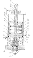
- FIG. 1 shows a longitudinal section through a Actuator for brakes on rail vehicles.
- the actuating device consists of a piston-cylinder arrangement with a Cylinder 1, the end with a cylinder bottom 2 and a cylinder cover 3rd is closed.
- a brake piston 4 is located inside the cylinder 1 opposite the wall of the cylinder 1 by means of an annular, in a outer radial groove in the brake piston 4 recessed seal 5 is sealed.
- Coaxial with the brake piston 4 is a cylinder cap 3 penetrating one Piston rod 6 for brake actuation.
- the cylinder cover 3 is on the Penetration point with an annular seal 7, which is also a Performs a guiding function for piston rod 6.
- a Pressure medium connection 8 is provided for the operating pressure.
- the piston rod 6 can be reset by a, not shown in the figure Counterforce generating brake linkage serve with the piston rod 6 of the Piston-cylinder arrangement via a mounting hole 9 in on the piston rod side Connection is established.
- a cylinder-side mounting hole 10 is used for stationary Attachment of the piston-cylinder arrangement in a likewise not in the figure frame shown near the brake or braking one Rail vehicle.
- the piston-cylinder arrangement is also one in the area of the cylinder bottom 2 integrated adjustment device.
- the adjustment device has one End stop on the cylinder bottom for the brake piston 4 adjusting piston 11, which is opposite the wall of the cylinder 1 with an annular in a outer radial groove in the adjusting piston 11 inserted seal 12 is sealed.
- the adjusting piston 11 coaxially goes in the direction of the cylinder base 2 Piston rod extension.
- the piston rod shoulder is external radial with a barb-like teeth 13 provided.
- the toothing 13 engages in one complementary toothing on the end face of a sleeve-shaped Holding element 15 a.
- the sleeve-shaped holding element is supported on its Gearing opposite end from the cylinder base 2.
- the barbed one Toothing 13 allows movement of the adjusting piston 11 in the direction of Brake piston 4 for wear clearance compensation.
- the counter movement is due to the locking mechanism, caused by the barb-like Design of the teeth 13, locked, so that the adjusting piston 11 its Can perform adjustment and stop function. So that is always a small one Ensured pressure medium consumption for the operation of the brake piston 4 and the Extension times of the piston rod 6 can be kept almost constant, what advantageous constant operating times of the downstream brake causes.
- the readjustment movement of the readjusting piston 11 is carried out between the Cylinder base 2 and the adjusting piston 11 formed with pressure medium acted upon cylinder space 14 made.
- the application of Pressure medium takes place via a pressure medium connection 16 on the cylinder 1 Allowing pressure to be applied in a controlled manner is the Pressure fluid connection 16 provided with an adjustable throttle 17.
- One of those Controlled pressurization can also be omitted if the Adjustment device includes a pawl, the per loading operation of the Cylinder chamber 14 allows only one tooth step for the adjustment.
- the piston-cylinder arrangement also has an integrated one Parking brake application.
- the brake piston 4 is cylindrical on the inside hollow.
- the brake piston 4 contains a parking brake piston 22.
- Die Piston rod 6 is coaxially formed on the end of the parking brake piston 22 and coaxially penetrates the brake piston 4. The penetration point in the brake piston 4 is sealed.
- the parking brake piston 22 comes on a pin-like Stop 24 to the system.
- a compression spring 26 is housed in the hollow cylindrical spring chamber 25 through the Length of the stop 24 and the inner diameter of the cylindrical hollow Brake piston 4 is formed.
- the compression spring 26 serves to act on the parking brake piston 22. Their effect will then triggered when the on the opposite side of the parking brake piston 22nd arranged pressure chamber 23 is vented.
- the pressure chamber 23 is a acted upon along the piston rod 6 extending pressure medium channel 31 and vented into a pressure medium connection 30 located outside the cylinder 1 flows. To this extent, a safety function can be carried out by this arrangement, in which a falling pressure in the system to trigger the pressure-independent Parking brake leads.
- the piston-cylinder arrangement according to the invention is one of the operating path of the Brake piston 4 measuring device 32 can be completed. That from the Position measuring device 32 - which is specially designed in the manner of a sliding resistance can be and is connected to the piston rod 6 - output electrical Travel signal is supplied to an electronic unit, not shown in the figure. The Electronics unit compares the current amount from the brake piston distance covered with a limit amount. When you reach this Limit travel amount - due to progressive wear of the brake pads a signal for a readjustment output, so that via a Pressurizing the cylinder chamber 14 with an adjustment movement of the on the cylinder bottom side serving as an end stop for the brake piston 4 Adjustment piston 11 takes place. The adjustment path is also carried out via the Wegmeß worn 32 checked and the pressure medium Cylinder chamber 14 then stopped as soon as the brake piston 4 also moved is registered.
- the actuating device according to the invention for those with wear play Machine elements - such as brakes and clutches - with integrated Adjustment device is characterized by a compact and comparatively simple structure and offers constructive prerequisites for this in one automatic overall system to be integrated.
Landscapes
- Engineering & Computer Science (AREA)
- General Engineering & Computer Science (AREA)
- Mechanical Engineering (AREA)
- Transportation (AREA)
- Braking Arrangements (AREA)
Abstract
Description
Die Erfindung betrifft eine Betätigungseinrichtung für verschleißspielbehaftete Maschinenelemente, insbesondere für Bremsen von Schienenfahrzeugen, gemäß dem Oberbegriff des Patentanspruches 1.The invention relates to an actuating device for those with play Machine elements, in particular for brakes on rail vehicles, according to the preamble of claim 1.
Als verschleißspielbehaftete Maschinenelemente im Sinne der vorliegenden Erfindung werden Maschinenelemente wie Kupplungen oder Bremsen angesehen. Derartige Maschinenelemente werden insbesondere zur Übertragung von Antriebs- bzw. Bremskräften bei Schienenfahrzeugen eingesetzt. Zum Unterbrechen und Schließen des Kraftflusses kommen Beläge zum Einsatz, die zum einen hohe thermische Beanspruchungen standhalten und zum anderen einen günstigen Kraftflußverlauf ermöglichen. Diese Beläge unterliegen einem Verschleiß, der ein sich allmählich vergrößerndes Verschleißspiel verursacht. Zum Ausgleich dieses Verschleißspiels sind Nachstelleinrichtungen bekannt.As machine elements subject to wear play within the meaning of the present invention machine elements such as clutches or brakes are considered. Such Machine elements are used in particular for the transmission of drive or Braking forces used in rail vehicles. For interrupting and closing of the power flow, linings are used, which on the one hand have high thermal Withstand stress and, on the other hand, a favorable flow of force flow enable. These rubbers are subject to wear and tear which gradually increases increasing wear play causes. To compensate for this wear play adjustment devices are known.
So geht beispielsweise aus der EP 0 174 690 eine Nachstelleinrichtung nach Art einer Stellmutter-Spindel-Baugruppe zum Verschleißspielausgleich für Bremsen hervor. Diese Nachstelleinrichtung baut auf einer Steuerhülse auf, die unter Federkraft stehend über eine erste Kupplung verhindert, daß eine Stellmutter über eine Drehbewegung eine Längsverstellung der Kolbenspindel und insoweit eine Nachstellung bewirkt. Nach Durchlaufen eines vorbestimmten Spielweges wird durch Verschieben der Kolbenstange über einen bestimmten Weg hinaus die erste Kupplung gelöst, so daß die Verstellung des Spielweges entsprechend dem eingetretenen Belagverschleiß erhöht werden kann. Eine weitere Kolbenvorschubbewegung hat das Einkuppeln einer zweiten Kupplung zur Folge, so daß daraufhin die Verstellung der Stellmutter auf der Spindel gestoppt wird. Dieser komplizierte Mechanismus für das Ein- und Auskuppeln der Stellmutter verursacht einen hohen Bauteil- und Montageaufwand für die Fertigung dieser Nachstelleinrichtung.For example, EP 0 174 690 describes an adjusting device of the type Adjusting nut-spindle assembly for wear play compensation for brakes. This adjustment device is based on a control sleeve, which is under spring force standing over a first coupling prevents an adjusting nut over a Rotational movement is a longitudinal adjustment of the piston spindle and in so far one Adjustment causes. After passing through a predetermined play path, through Move the piston rod a certain way beyond the first Coupling released, so that the adjustment of the play path according to the wear that has occurred can be increased. Another Piston feed movement results in the engagement of a second clutch, see above that the adjustment of the adjusting nut on the spindle is then stopped. This complicated mechanism for engaging and disengaging the adjusting nut a high component and assembly effort for the production of these Adjuster.
Wie aus der DE-OS 22 01 082 hervorgeht, wird eine Nachstelleinrichtung für Schienenfahrzeugbremsen in Verbindung mit einer Kolben-Zylinder-Anordnung zur Bremsbetätigung und einem Bremsgestänge zur Bremskraftübertragung eingesetzt. Die bekannten Betätigungseinrichtungen bestehen demnach aus mehreren einzelnen zu verbindenden Baugruppen, was deren Montage aufwendig gestaltet. Weiterhin sind bekannte Betätigungseinrichtungen autarke Systeme und daher nicht hinsichtlich ihres Betriebszustandes und Verschleißzustandes von einem übergeordneten Gesamtsystem aus überwachbar und von diesem differenziert ansteuerbar. Die Voraussetzung für eine aktive Integration in ein übergeordnetes Gesamtsystem sind bei bekannten Betätigungseinrichtungen demnach nicht gegeben.As is apparent from DE-OS 22 01 082, an adjusting device for Rail vehicle brakes in connection with a piston-cylinder arrangement Brake actuation and a brake linkage used for brake force transmission. The known actuators therefore consist of several individual assemblies to be connected, which makes their assembly complex. Farther are known actuators self-sufficient systems and therefore not in terms of their operating status and wear status from a higher-level Entire system can be monitored and controlled differently from it. The Active integration into a higher-level overall system is a prerequisite not given in known actuators.
Der Erfindung liegt daher die Aufgabe zugrunde, eine Betätigungseinrichtung, insbesondere für Bremsen von Schienenfahrzeugen zu schaffen, die zum einen einfach und kompakt aufgebaut ist und zum anderen Voraussetzungen für die aktive Integration in ein übergeordnetes Gesamtsystem erfüllt.The invention is therefore based on the object of an actuating device, to create in particular for brakes of rail vehicles, on the one hand is simple and compact and on the other hand it is a requirement for the active Integration into a higher-level overall system fulfilled.
Die Erfindung wird ausgehend von einer Betätigungseinrichtung für verschleißspielbehaftete Maschinenelemente gemäß dem Oberbegriff des Patentanspruches 1 in Verbindung mit dessen kennzeichnenden Merkmalen gelöst.The invention is based on an actuator for machine elements subject to wear play according to the preamble of Patent claim 1 in connection with its characteristic features solved.
Die Erfindung schließt die technische Lehre ein, daß die Betätigungseinrichtung für verschleißspielbehaftete Maschinenelemente aus einem in einer Kolben-Zylinder-Anordnung kolbenbodenseitig integrierten und als Endanschlag für einen Bremskolben ausgebildeten Nachstellkolben aufgebaut ist, der zur axialen Arretierung einen dem Kolbenboden zugewandten koaxialen Kolbenstangenansatz aufweist, der gemeinsam mit einem sich am Zylinderboden abstützenden Halteelement eine Arretierungsanordnung bildet, welche eine Bewegung des Nachstellkolbens in Richtung des Bremskolbens ermöglicht und die entsprechende Gegenbewegung sperrt. Dabei ist zur Bewegung des Nachstellkolbens ein zwischen dem Zylinderboden und dem Nachstellkolben gebildeter Zylinderraum über einen Anschluß mit Druckmittel beaufschlagbar. The invention includes the technical teaching that the actuator for Machine elements subject to wear play from one in a piston-cylinder arrangement integrated on the piston bottom side and as an end stop for one Brake piston trained adjustment piston is constructed for axial locking has a coaxial piston rod extension facing the piston crown, which together with a holding element supported on the cylinder base Locking arrangement which forms a movement of the adjusting piston in Direction of the brake piston and the corresponding counter movement locks. There is a between the movement of the adjusting piston Cylinder base and the adjusting piston formed cylinder space via a connection pressurizable.
Somit ist die Nachstelleinrichtung der Betätigungseinrichtung direkt in die Kolben-Zylinder-Anordnung integriert und bildet mit ihr eine kompakte Baueinheit. Die Nachstelleinrichtung zeichnet sich durch eine geringe Anzahl von Bauteilen und durch ihren insoweit einfachen Aufbau aus. Da der Nachstellkolben ebenso wie der Bremskolben separat über Druckmittel von außen her betreibbar ist, ist die Betätigungseinrichtung damit differenziert von einem übergeordneten Gesamtsystem aus ansteuerbar. Dieses ist eine entscheidende Voraussetzung für die Integration beispielsweise in ein elektronisch angesteuertes Bremssystem eines Schienenfahrzeuges.The adjusting device of the actuating device is thus directly in the piston-cylinder arrangement integrates and forms a compact unit with it. The Adjustment device is characterized by a small number of components and by their simple structure. Since the adjusting piston as well as the Brake piston can be operated separately via pressure medium from the outside, is the Actuating device differentiated from a higher-level overall system controllable from. This is a crucial requirement for integration for example in an electronically controlled braking system Rail vehicle.
Eine weitere diese Integrationsfähigkeit verbessernde Maßnahme besteht darin, daß eine elektrische Wegmeßeinrichtung - die beispielsweise nach Art eines Schiebewiderstandes oder auch berührungslos mittels einer induktiven oder kapazitiven Wegmeßeinrichtung ausgebildet ist - den Betrag des vom Bremskolben zurückgelegten Weges erfaßt und zur Ermittlung einer Nachstellaktion einer Elektronikeinheit eingangsseitig zur Verfügung stellt, die bei Erreichen eines Grenzwegbetrages ausgangsseitig ein Signal für die Nachstellaktion generiert. Damit ist die Betätigungseinrichtung auch bidirektional mit dem Gesamtsystem kommunizierend betreibbar, was insgesamt einen hohen Automatisierungsgrad gewährleistet.Another measure that improves this ability to integrate is that an electrical displacement measuring device - which, for example, in the manner of a Sliding resistance or contactless by means of an inductive or capacitive displacement measuring device is formed - the amount of the brake piston covered distance and to determine a readjustment of a Provides electronics unit on the input side, which is reached when a A limit signal for the adjustment action is generated on the output side. In order to the actuator is also bidirectional with the overall system operable communicating, which is a high degree of automation overall guaranteed.
Vorzugsweise weist zur Arretierung der Nachstelleinrichtung der Kolbenstangenansatz des Nachstellkolbens eine widerhakenartige Verzahnung auf, die über eine komplementär dazu ausgebildete Verzahnung an einem Halteelement rastend korrespondiert. Diese Arretierungsanordnung für die Nachstelleinrichtung zeichnet sich durch einen einfachen und zugleich zuverlässig wirkenden Aufbau aus. Zur Rückstellung der Nachstelleinrichtung ist vorzugsweise eine koaxial in den Kolbenboden geschraubte, mit einem endseitig zumindest innen konisch ausgebildeten Abschnitt des Halteelementes zusammenwirkende und das Halteelement über einen Konus aufspreizende Hohlschraube vorgesehen. Zur Aufspreizbarkeit ist das Halteelement mit mindestens zwei Längsschlitzen versehen. Preferably, for locking the adjusting device Piston rod approach of the adjusting piston has barb-like teeth, the complementary toothing on a holding element corresponds with a rest. This locking arrangement for the adjusting device is characterized by a simple yet reliable structure. To reset the adjusting device is preferably a coaxial in the Piston base screwed, with a conical end at least on the inside trained section of the holding element cooperating and that Holding element provided via a cone-expanding hollow screw. For Spreadability, the holding element is provided with at least two longitudinal slots.
Die Kolben-Zylinder-Anordnung besitzt vorteilhafter Weise ein zwischen dem Nachstellkolben und dem Bremskolben gebildeten Zylinderraum, der über einen Druckmittelanschluß zur Bewegung des Bremskolbens beaufschlagbar ist. Zur Rückstellung des Bremskolbens kann ein sich der Kolbenstange anschließendes Bremsgestänge oder eine in die Kolben-Zylinder-Anordnung integrierte und zwischen dem Bremskolben und dem Zylinderdeckel angeordnete Rückstellfeder vorgesehen sein.The piston-cylinder arrangement advantageously has a between the Adjustment piston and the brake piston formed cylinder space, which has a Pressure medium connection for moving the brake piston can be acted upon. For The brake piston can be reset by connecting the piston rod Brake linkage or an integrated in the piston-cylinder arrangement and between the return piston provided the brake piston and the cylinder cover be.
Eine weitere die Erfindung verbessernde Maßnahme besteht darin, daß die Betätigungseinrichtung mit einer integrierten Feststellbremse ausgerüstet ist. Dafür ist der Bremskolben innen zylinderartig hohl ausgebildet und mit einem integrierten Feststellbremskolben versehen, der über eine Druckfeder betätigbar ist, wobei der Feststellbremskolben mit der Kolbenstange in Wirkverbindung steht. Zur Rückstellung und Arretierung des Feststellbremskolbens kann insbesondere eine der Druckfeder entgegensetzt wirkende und über einen Anschluß mit Druckmittel beaufschlagbare Druckkammer vorgesehen werden. Dabei kann zur Druckmittelbeaufschlagung die Kolbenstange mit einem vom Bereich des Feststellbremskolbens ausgehenden, längs der Kolbenstange verlaufenden und im Bereich ihres freien Endes in einen Druckmittelanschluß mündenden Druckmittelkanal ausgestattet sein. Alternativ dazu ist es auch denkbar, zur Druckmittelbeaufschlagung einen von einer Durchgangsbohrung im Feststellbremskolben ausgehenden und in eine als Druckmittelanschluß ausgebildete Durchgangsbohrung im Zylinderdeckel mündenden flexiblen Druckmittelschlauch zu verwenden. Ebenso kann auch eine von einer Durchgangsbohrung zur Druckkammer im Betriebsbremskolben ausgehende und parallel zur Kolbenstange verlaufende starre Rohrleitung, die über eine ringförmige Dichtung aus dem Zylinderdeckel längs bewegbar austritt, zur Druckmittelbeaufschlagung der rückstellenden Druckkammer der Feststellbremse verwendet werden.Another measure improving the invention is that the Actuator is equipped with an integrated parking brake. For that is the inside of the brake piston is cylindrical and has an integrated one Parking brake piston provided, which is actuated by a compression spring, the Parking brake piston is in operative connection with the piston rod. To reset and locking the parking brake piston can in particular one of the compression spring oppositely acting and pressurizable via a connection Pressure chamber are provided. It can be used to apply pressure Piston rod with a longitudinally extending from the area of the parking brake piston the piston rod and in the area of its free end in one Pressure medium connection opening pressure medium channel be equipped. Alternatively it is also conceivable to pressurize one of one Through hole in the parking brake piston outgoing and in an as Pressure medium connection formed through hole in the cylinder cover opening use flexible pressure hose. Likewise, one of one Through hole to the pressure chamber in the service brake piston outgoing and Rigid pipeline running parallel to the piston rod Gasket emerges from the cylinder cover to move longitudinally Pressurization of the restoring pressure chamber of the parking brake be used.
Die vorstehend beschriebenen Ausgestaltungsformen der Erfindung beziehen sich speziell auf eine Anwendung bei einem Bremssystem, insbesondere einem Bremssystem von Schienenfahrzeugen. Die erfindungsgemäße Lösung kann jedoch gleichfalls auf alle gattungsgemäßen druckmittelbetriebenen Betätigungseinrichtungen angewendet werden, die zur Betätigung verschleißspielbehafteter Maschinenelemente eingesetzt werden, beispielsweise auch Kupplungen unterschiedlichster Art.The embodiments of the invention described above relate specifically for an application in a braking system, in particular one Braking system of rail vehicles. However, the solution according to the invention can likewise on all generic pressure medium operated Actuators are used for actuation machine elements subject to wear play are used, for example also Various types of couplings.
Weitere die Erfindung verbessernde Maßnahmen werden nachstehend gemeinsam mit der Beschreibung einer bevorzugten Ausführungsform der Erfindung anhand der einzigen Figur näher dargestellt. Die Figur zeigt einen Längsschnitt durch eine Betätigungseinrichtung für Bremsen von Schienfahrzeugen.Further measures improving the invention are described below with the description of a preferred embodiment of the invention using the single figure shown in more detail. The figure shows a longitudinal section through a Actuator for brakes on rail vehicles.
Die Betätigungseinrichtung besteht aus einer Kolben-Zylinder-Anordnung mit einem
Zylinder 1, der endseitig mit einem Zylinderboden 2 sowie einem Zylinderdeckel 3
verschlossen ist. Innerhalb des Zylinders 1 befindet sich ein Bremskolben 4, der
gegenüber der Wandung des Zylinders 1 mittels einer ringförmigen, in einer
außenradialen Nut im Bremskolben 4 eingelassenen Dichtung 5 abgedichtet ist.
Koaxial vom Bremskolben 4 geht eine den Zylinderdeckel 3 durchdringende
Kolbenstange 6 zur Bremsbetätigung aus. Der Zylinderdeckel 3 ist an der
Durchdringungsstelle mit einer ringförmigen Dichtung 7, die zugleich eine
Führungsfunktion für Kolbenstange 6 ausübt, versehen. Am Zylinder 1 ist ein
Druckmittelanschluß 8 für den Betriebsdruck vorgesehen. Wird über den
Druckmittelanschluß 8 der Bremskolben 4 auf seiner der Kolbenstange 6
abgewandten Seite mit Druckmittel beaufschlagt, so fährt die Kolbenstange 6 aus. Die
Rückstellung der Kolbenstange 6 kann durch ein in der Figur nicht dargestelltes, eine
Gegenkraft erzeugendes Bremsgestänge dienen, das mit der Kolbenstange 6 der
Kolben-Zylinder-Anordnung über eine kolbenstangenseitige Befestigungsbohrung 9 in
Verbindung steht. Eine zylinderseitige Befestigungsbohrung 10 dient der ortsfesten
Befestigung der Kolben-Zylinder-Anordnung in einem ebenfalls in der Figur nicht
dargestellten Gestell in der Nähe der Bremse oder Bremsen eines
Schienenfahrzeuges.The actuating device consists of a piston-cylinder arrangement with a
Cylinder 1, the end with a
Die Kolben-Zylinder-Anordnung ist weiterhin mit einer im Bereich des Zylinderbodens
2 integrierten Nachstelleinrichtung ausgerüstet. Die Nachstelleinrichtung besitzt einen
zylinderbodenseitigen Endanschlag für den Bremskolben 4 bildenden Nachstellkolben
11, der gegenüber der Wandung des Zylinders 1 mit einer ringförmigen in einer
außenradialen Nut im Nachstellkolben 11 eingelassenen Dichtung 12 abgedichtet ist.
Vom Nachstellkolben 11 geht koaxial in Richtung des Zylinderbodens 2 ein
Kolbenstangenansatz aus. Der Kolbenstangenansatz ist außenradial mit einer
widerhakenartigen Verzahnung 13 versehen. Die Verzahnung 13 greift in eine
komplementär dazu ausgestaltete Verzahnung an der Stirnseite eines hülsenförmigen
Halteelementes 15 ein. Das hülsenförmige Halteelement stützt sich an seinem der
Verzahnung entgegengesetzten Ende am Zylinderboden 2 ab. Die widerhakenartige
Verzahnung 13 ermöglicht eine Bewegung des Nachstellkolbens 11 in Richtung des
Bremskolbens 4 zum Zwecke eines Verschleißspielausgleiches. Die Gegenbewegung
ist aufgrund des Rastmechanismus, verursacht durch die widerhakenartige
Ausgestaltung der Verzahnung 13, gesperrt, so daß der Nachstellkolben 11 seine
Nachstell- und Anschlagfunktion ausüben kann. Damit ist ein stets kleiner
Druckmittelverbrauch für den Betrieb des Bremskolbens 4 sichergestellt und die
Ausfahrzeiten der Kolbenstange 6 können nahezu konstant gehalten werden, was
vorteilhaft konstant bleibende Betätigungszeiten der nachgeschalteten Bremse
bewirkt.The piston-cylinder arrangement is also one in the area of the
Die Nachstellbewegung des Nachstellkolbens 11 wird über einen zwischen dem
Zylinderboden 2 und dem Nachstellkolben 11 gebildeten mit Druckmittel
beaufschlagbaren Zylinderraum 14 vorgenommen. Die Beaufschlagung mit
Druckmittel erfolgt dabei über einen Druckmittelanschluß 16 am Zylinder 1. Um die
Druckmittelbeaufschlagung kontrolliert erfolgen zu lassen, ist der
Druckmitttelanschluß 16 mit einer einstellbaren Drossel 17 versehen. Eine derartig
kontrollierte Druckmittelbeaufschlagung kann auch entfallen, wenn die
Nachstelleinrichtung eine Sperrklinke umfaßt, die pro Beaufschlagungsvorgang des
Zylinderraumes 14 nur einen Zahnschritt für die Nachstellung ermöglicht.The readjustment movement of the readjusting
Mit dem Wechsel von verschlissenen Bremsbelegen ist es notwendig, den
Nachstellkolben 11 wieder in seine zylinderbodennahe in der Figur dargestellte
Ausgangsposition zurückzustellen. Zum Rückstellen dient eine koaxial in den
Zylinderboden 2 eingeschraubte Hohlschraube 18. Die Hohlschraube 18 drückt beim
Einschrauben gegen mehrere ringförmig in den Zylinderboden eingelassene und
jeweils mit Dichtungen 19, 19' ihm gegenüber abgedichtete Zylinderstifte 20, 20'. Die
Zylinderstifte 20, 20' drücken infolge dessen gegen einen ringartig ausgebildeten
Konus 21. Der Konus 21 spreizt das Halteelement 15 in seinem Verzahnungsbereich
auf, so daß die Arretierung des Nachstellkolbens 11 gelöst ist und über die
Kolbenstange 6 eine Rückstellung des Nachstellkolbens 11 erfolgen kann. Die
Spreizbarkeit des Halteelementes 15 wird über mehrere im Verzahnungsbereich
angeordnete in der Figur nicht dargestellte Längsschlitze ermöglicht.With the change of worn brake pads it is necessary to
Adjusting
Die Kolben-Zylinder-Anordnung besitzt weiterhin eine integrierte
Feststellbremsbetätigung. Zu diesem Zweck ist der Bremskolben 4 innen zylinderartig
hohl ausgebildet. Der Bremskolben 4 enthält einen Feststellbremskolben 22. Die
Kolbenstange 6 ist koaxial am Feststellbremskolben 22 endseitig angeformt und
durchdringt koaxial den Bremskolben 4. Die Durchdringungsstelle im Bremskolben 4
ist dabei abgedichtet. Der Feststellbremskolben 22 kommt an einem zapfenartigen
Anschlag 24 zur Anlage. In dem hohlzylinderförmigen Federraum 25, der durch die
Länge des Anschlages 24 und dem Innendurchmesser des zylindrisch hohlen
Bremskolbens 4 gebildet ist, ist eine Druckfeder 26 untergebracht. Die Druckfeder 26
dient der Beaufschlagung des Feststellbremskolbens 22. Ihre Wirkung wird dann
ausgelöst, wenn die auf der entgegengesetzten Seite des Feststellbremskolbens 22
angeordnete Druckkammer 23 entlüftet wird. Die Druckkammer 23 wird über einen
längs der Kolbenstange 6 verlaufenden Druckmittelkanal 31 beaufschlagt und
entlüftet, der in einen außerhalb des Zylinders 1 gelegenen Druckmittelanschluß 30
mündet. Insoweit ist durch diese Anordnung eine Sicherheitsfunktion durchführbar,
bei der ein abfallender Druck im System zum Auslösen der druckmittelunabhängigen
Feststellbremse führt.The piston-cylinder arrangement also has an integrated one
Parking brake application. For this purpose, the
Die erfindungsgemäße Kolben-Zylinder-Anordnung ist mit einer den Betriebsweg des
Bremskolbens 4 erfassenden Wegmeßeinrichtung 32 komplettierbar. Das von der
Wegmeßeinrichtung 32 - die speziell nach Art eines Schiebewiderstandes ausgebildet
sein kann und mit der Kolbenstange 6 in Verbindung steht - ausgegebene elektrische
Wegsignal wird einer in der Figur nicht dargestellten Elektronikeinheit zugeführt. Die
Elektronikeinheit vergleicht den aktuellen Betrag des vom Bremskolben
zurückgelegten Weges mit einem Grenzwegbetrag. Bei Erreichen dieses
Grenzwegbetrages - infolge voranschreitenden Verschleißes der Bremsbeläge - wird
ein Signal für eine Nachstellaktion ausgegeben, so daß über eine
Druckmittelbeaufschlagung des Zylinderraumes 14 eine Nachstellbewegung des
zylinderbodenseitig als Endanschlag für den Bremskolben 4 dienenden
Nachstellkolben 11 erfolgt. Dabei wird der vollzogene Nachstellweg ebenfalls über die
Wegmeßeinrichtung 32 kontrolliert und die Druckmittelbeaufschlagung des
Zylinderraumes 14 dann gestoppt, sobald eine Mitbewegung des Bremskolbens 4
registriert wird.The piston-cylinder arrangement according to the invention is one of the operating path of the
Die erfindungsgemäße Betätigungseinrichtung für verschleißspielbehaftete Maschinenelemente - wie Bremsen und Kupplungen - mit integrierter Nachstelleinrichtung zeichnet sich durch einen kompakten und vergleichsweise einfachen Aufbau aus und bietet konstruktive Voraussetzungen dafür, in einem automatischen Gesamtsystem integriert zu werden. The actuating device according to the invention for those with wear play Machine elements - such as brakes and clutches - with integrated Adjustment device is characterized by a compact and comparatively simple structure and offers constructive prerequisites for this in one automatic overall system to be integrated.
- 11
- Zylindercylinder
- 22nd
- ZylinderbodenCylinder bottom
- 33rd
- ZylinderdeckelCylinder cover
- 44th
- BremskolbenBrake piston
- 55
- Dichtungpoetry
- 66
- KolbenstangePiston rod
- 77
- Dichtung, führendPoetry, leader
- 88th
- DruckmittelanschlußPressure fluid connection
- 99
- Befestigungsbohrung, kolbenstangenseitigFastening hole, on the piston rod side
- 1010th
- Befestigungsbohrung, zylinderseitigFastening hole, on the cylinder side
- 1111
- NachstellkolbenAdjusting piston
- 1212th
- Dichtungpoetry
- 1313
- VerzahnungGearing
- 1414
- ZylinderraumCylinder space
- 1515
- HalteelementHolding element
- 1616
- DruckmittelanschlußPressure fluid connection
- 1717th
- Drosselthrottle
- 1818th
- HohlschraubeBanjo bolt
- 1919th
- Dichtungpoetry
- 2020th
- ZylinderstiftDowel pin
- 2121
- Konuscone
- 2222
- FeststellbremskolbenParking brake piston
- 2323
- DruckkammerPressure chamber
- 2424th
- Anschlagattack
- 2525th
- FederraumSpring chamber
- 2626
- DruckfederCompression spring
- 3030th
- DruckmittelanschlußPressure fluid connection
- 3131
- DruckmittelkanalPressure medium channel
- 3232
- WegmeßeinrichtungPosition measuring device
Claims (12)
dadurch gekennzeichnet,
daß die Nachstelleinrichtung aus einem in der Kolben-Zylinder-Anordnung kolbenbodenseitig integrierten und als Endanschlag für einen Bremskolben (4) ausgebildeten Nachstellkolben (11) aufgebaut ist, der zur axialen Arretierung einen dem Zylinderboden (2) zugewandten koaxialen Kolbenstangenansatz aufweist, der gemeinsam mit einem sich am Zylinderboden (2) abstützenden Halteelement (15) eine Arretierungsanordnung bildet, welche eine Bewegung des Nachstellkolbens (11) in Richtung des Bremskolbens (4) ermöglicht und die Gegenbewegung sperrt, wobei zur Bewegung des Nachstellkolbens (11) ein zwischen dem Zylinderboden (2) und dem Nachstellkolben (11) gebildeter Zylinderraum (14) über einen Druckmittelanschluß (16) mit Druckmittel beaufschlagbar ist.Actuating device for machine elements subject to wear play, in particular for brakes of rail vehicles, with a pressure medium-operated piston-cylinder arrangement, the piston rod of which is operatively connected to an adjustment device which compensates for wear play,
characterized,
that the adjusting device is constructed from an adjusting piston (11) integrated in the piston-cylinder arrangement on the piston bottom side and designed as an end stop for a brake piston (4), which has a coaxial piston rod attachment facing the cylinder bottom (2) for axial locking, which together with a a retaining element (15) which supports the cylinder base (2) forms a locking arrangement which enables the adjustment piston (11) to move in the direction of the brake piston (4) and blocks the counter-movement, with a movement between the cylinder base (2 ) and the adjusting piston (11) formed cylinder space (14) via a pressure medium connection (16) can be acted upon with pressure medium.
dadurch gekennzeichnet,
daß eine elektrische Wegmeßeinrichtung (32) den Betrag des vom Bremskolben (4) zurückgelegten Weges erfaßt und zur Ermittlung einer Nachstellaktion einer Elektronikeinheit eingangsseitig zur Verfügung stellt, die bei Erreichen eines vorgegebenen Grenzwegbetrages ausgangsseitig ein Signal für die Nachstellaktion generiert.Actuating device according to claim 1,
characterized,
that an electrical displacement measuring device (32) detects the amount of the distance covered by the brake piston (4) and makes it available on the input side for determining a readjustment action, which generates a signal for the readjustment action on the output side when a predetermined limit travel amount is reached.
dadurch gekennzeichnet,
daß die elektrische Wegmeßeinrichtung (32) nach Art eines Schiebewiderstandes ausgebildet ist und mit der Kolbenstange (6) des Bremskolbens (4) in Verbindung steht. Actuating device according to claim 2,
characterized,
that the electrical displacement measuring device (32) is designed in the manner of a sliding resistance and is connected to the piston rod (6) of the brake piston (4).
dadurch gekennzeichnet,
daß zur Arretierung der Nachstelleinrichtung der Kolbenstangenansatz des Nachstellkolbens (11) eine widerhakenartige Verzahnung (13) aufweist, die mit einem komplementär dazu verzahnten hülsenartigen Halteelement (15) rastend korrespondiert.Actuating device according to one of the preceding claims,
characterized,
that for locking the adjusting device the piston rod extension of the adjusting piston (11) has barb-like teeth (13) which correspond with a complementary toothed sleeve-like holding element (15).
dadurch gekennzeichnet,
daß zur Rückstellung der Nachstelleinrichtung eine durch den Kolbenboden (2) geschraubte Hohlschraube (18) vorgesehen ist, die mit einem endseitig zumindest innen konisch ausgebildeten Abschnitt des Halteelementes (15) eingreifenden, das Halteelement (15) aufspreizenden Konus (21) zusammenwirkt, wobei zur Aufspreizbarkeit das Halteelement (15) mit mindestens zwei Längsschlitzen versehen ist.Actuating device according to one of the preceding claims,
characterized,
that to reset the adjusting device a through the piston head (2) screwed banjo bolt (18) is provided, which engages with a conical end portion of the holding element (15), the holding element (15) spreading cone (21), whereby the Spreadability, the holding element (15) is provided with at least two longitudinal slots.
dadurch gekennzeichnet,
daß zur Betätigung im Bremsbetrieb ein zwischen dem Nachstellkolben (11) und dem Bremskolben (4) gebildeter Zylinderraum (14) über einen Druckmittelanschluß (16) mit Druckmittel beaufschlagbar ist.Actuating device according to one of the preceding claims,
characterized,
that a cylinder space (14) formed between the adjusting piston (11) and the brake piston (4) can be acted upon via a pressure medium connection (16) with pressure medium for actuation in the braking mode.
dadurch gekennzeichnet,
daß zur Rückstellung des Bremskolben (4) ein sich der Kolbenstange (6) anschließendes, eine Rückstellkraft ausübendes Bremsgestänge oder eine in die Kolben-Zylinder-Anordnung integrierte und zwischen dem Bremskolben (4) und dem Zylinderdeckel (3) angeordnete Rückstellfeder vorgesehen ist. Actuating device according to one of the preceding claims,
characterized,
that to reset the brake piston (4) is a piston rod (6) adjoining, a restoring force exerting brake linkage or integrated in the piston-cylinder arrangement and arranged between the brake piston (4) and the cylinder cover (3) return spring.
dadurch gekennzeichnet,
daß der Bremskolben (4) innen zylinderartig hohl ausgebildet ist und mit einem integrierten Feststellbremskolben (22) zusammenwirkt, der über eine Druckfeder (26) betätigbar ist, wobei der Feststellbremskolben (22) mit der Kolbenstange (6) in Verbindung steht.Actuating device according to one of the preceding claims,
characterized,
that the brake piston (4) is hollow on the inside and cooperates with an integrated parking brake piston (22) which can be actuated via a compression spring (26), the parking brake piston (22) being connected to the piston rod (6).
dadurch gekennzeichnet,
daß zur Rückstellung und Arretierung des Feststellbremskolbens (22) eine der Druckfeder (26) entgegengesetzt wirkende und über einen Druckmittelanschluß (30) mit Druckmittel beaufschlagbare Druckkammer (23) vorgesehen ist.Actuating device according to one of the preceding claims,
characterized,
that for resetting and locking the parking brake piston (22) there is provided a pressure chamber (23) which acts counter to the pressure spring (26) and can be acted upon by a pressure medium connection (30).
dadurch gekennzeichnet,
daß zur Druckmittelbeaufschlagung der Feststellbremse die Kolbenstange (6) mit einem integrierten vom Bereich des Feststellbremskolbens (22) ausgehenden, längs der Kolbenstange (6) verlaufenden und im Bereich ihres freien Endes in einen Druckmittelanschluß (30) mündenden Druckmittelkanal (31) ausgestattet ist.Actuating device according to one of the preceding claims,
characterized,
that for the application of pressure medium to the parking brake, the piston rod (6) is equipped with an integrated pressure medium channel (31), starting from the area of the parking brake piston (22), running along the piston rod (6) and opening in the area of its free end into a pressure medium connection (30).
dadurch gekennzeichnet,
daß zur Druckmittelbeaufschlagung der Feststellbremse ein von einer Durchgangsbohrung im Feststellbremskolben (22) ausgehender und in eine als Druckmittelanschluß ausgebildete Durchgangsbohrung im Zylinderdeckel (3) mündender flexibler Druckmittelschlauch vorgesehen ist.Actuating device according to one of the preceding claims,
characterized,
that a flexible pressure medium hose is provided for pressurizing the parking brake, starting from a through hole in the parking brake piston (22) and opening into a through hole designed as a pressure medium connection in the cylinder cover (3).
dadurch gekennzeichnet,
daß zur Druckmittelbeaufschlagung der Feststellbremse eine von einer Durchgangsbohrung zur Druckkammer (23) im Bremskolben (4) ausgehende und parallel zur Kolbenstange verlaufende starre Rohrleitung, die über eine ringförmige Dichtung aus dem Zylinderdeckel (3) längs bewegbar austritt, vorgesehen ist.Actuating device according to one of the preceding claims,
characterized,
that for the application of pressure medium to the parking brake, a rigid pipe which extends from a through hole to the pressure chamber (23) in the brake piston (4) and runs parallel to the piston rod and exits longitudinally via an annular seal from the cylinder cover (3) is provided.
Applications Claiming Priority (2)
| Application Number | Priority Date | Filing Date | Title |
|---|---|---|---|
| DE19755896 | 1997-12-08 | ||
| DE19755896A DE19755896C2 (en) | 1997-12-08 | 1997-12-08 | Actuator for machine elements subject to wear, in particular for braking rail vehicles #### |
Publications (2)
| Publication Number | Publication Date |
|---|---|
| EP0921331A2 true EP0921331A2 (en) | 1999-06-09 |
| EP0921331A3 EP0921331A3 (en) | 2001-10-04 |
Family
ID=7852106
Family Applications (1)
| Application Number | Title | Priority Date | Filing Date |
|---|---|---|---|
| EP98250401A Withdrawn EP0921331A3 (en) | 1997-12-08 | 1998-11-19 | Actuating device for machine elements subject to wear, particularly for brakes of rail vehicles |
Country Status (3)
| Country | Link |
|---|---|
| US (1) | US6119826A (en) |
| EP (1) | EP0921331A3 (en) |
| DE (1) | DE19755896C2 (en) |
Cited By (1)
| Publication number | Priority date | Publication date | Assignee | Title |
|---|---|---|---|---|
| WO2015090344A1 (en) * | 2013-12-19 | 2015-06-25 | Wabco Europe Bvba | Brake cylinder |
Families Citing this family (2)
| Publication number | Priority date | Publication date | Assignee | Title |
|---|---|---|---|---|
| DE10214669B4 (en) * | 2002-04-03 | 2014-01-23 | Knorr-Bremse Systeme für Schienenfahrzeuge GmbH | Method and device for controlling an electrically operated wear adjustment device |
| DE102008031071B4 (en) * | 2008-07-01 | 2010-12-09 | Pintsch Bubenzer Gmbh | Device for travel control |
Citations (2)
| Publication number | Priority date | Publication date | Assignee | Title |
|---|---|---|---|---|
| DE2201082A1 (en) | 1971-01-12 | 1972-07-27 | Bromsregulator Svenska Ab | Pneumatic piston-cylinder unit for clamping devices for rail vehicle brakes |
| EP0174690A1 (en) | 1984-08-28 | 1986-03-19 | SAB WABCO Holdings B.V. | A rail vehicle slack adjuster |
Family Cites Families (10)
| Publication number | Priority date | Publication date | Assignee | Title |
|---|---|---|---|---|
| DE121815C (en) * | ||||
| DE1269426B (en) * | 1965-03-24 | 1968-05-30 | Bergische Stahlindustrie | Friction brake that can be released hydraulically against the force of a pressure spring, in particular a partially lined disc brake |
| JPS5138867B1 (en) * | 1970-02-04 | 1976-10-25 | ||
| US3908804A (en) * | 1974-07-11 | 1975-09-30 | Caterpillar Tractor Co | Service and parking brake actuation piston with adjuster mechanism |
| US4088205A (en) * | 1976-01-21 | 1978-05-09 | Wabco Westinghouse G.M.B.H. | Brake cylinder with built-in slack adjuster, including means for manually resetting piston travel |
| DE3106178A1 (en) * | 1981-02-19 | 1982-09-09 | Knorr-Bremse GmbH, 8000 München | AUTOMATIC ADJUSTMENT DEVICE FOR THE LIFTING STROKE OF BRAKE RODS OF IN PARTICULAR RAIL VEHICLES |
| DD203606A1 (en) * | 1982-03-12 | 1983-10-26 | Joachim Kreisl | FRICTION COUPLING AND BRAKE WITH AUTOMATIC WEAR ADJUSTMENT |
| DE3709952C1 (en) * | 1987-03-26 | 1988-08-25 | Richard Dipl-Ing Wilke | Electromotive brake actuation device for rail vehicles |
| DE19610664C2 (en) * | 1996-03-08 | 1998-02-19 | Mannesmann Ag | Brake cylinder device for rail vehicles |
| DE19734540C1 (en) * | 1997-07-30 | 1999-04-29 | Mannesmann Ag | Actuating device for machine elements subject to wear, in particular for brakes of rail vehicles |
-
1997
- 1997-12-08 DE DE19755896A patent/DE19755896C2/en not_active Expired - Fee Related
-
1998
- 1998-11-19 EP EP98250401A patent/EP0921331A3/en not_active Withdrawn
- 1998-12-08 US US09/207,231 patent/US6119826A/en not_active Expired - Fee Related
Patent Citations (2)
| Publication number | Priority date | Publication date | Assignee | Title |
|---|---|---|---|---|
| DE2201082A1 (en) | 1971-01-12 | 1972-07-27 | Bromsregulator Svenska Ab | Pneumatic piston-cylinder unit for clamping devices for rail vehicle brakes |
| EP0174690A1 (en) | 1984-08-28 | 1986-03-19 | SAB WABCO Holdings B.V. | A rail vehicle slack adjuster |
Cited By (2)
| Publication number | Priority date | Publication date | Assignee | Title |
|---|---|---|---|---|
| WO2015090344A1 (en) * | 2013-12-19 | 2015-06-25 | Wabco Europe Bvba | Brake cylinder |
| US9981646B2 (en) | 2013-12-19 | 2018-05-29 | Wabco Europe Bvba | Brake cylinder |
Also Published As
| Publication number | Publication date |
|---|---|
| DE19755896A1 (en) | 1999-06-17 |
| EP0921331A3 (en) | 2001-10-04 |
| DE19755896C2 (en) | 2000-04-13 |
| US6119826A (en) | 2000-09-19 |
Similar Documents
| Publication | Publication Date | Title |
|---|---|---|
| WO2018077464A1 (en) | Self-adjusting pneumatic clutch actuator | |
| DE19507308A1 (en) | Disc brake | |
| EP0544851A1 (en) | Pressure-controlled adjusting device for a vehicle brake. | |
| WO2018149616A1 (en) | Self-adjusting pneumatic clutch actuator | |
| DE19529791C2 (en) | Brake actuator with adjuster | |
| DE19734540C1 (en) | Actuating device for machine elements subject to wear, in particular for brakes of rail vehicles | |
| DE102019204349A1 (en) | Pressurized fluid actuator assembly for a friction clutch | |
| DE2453497B2 (en) | Hand brake actuation for brake cylinder | |
| EP0399194B1 (en) | Disc brake for vehicles | |
| DE2316822C2 (en) | Wear adjustment device for brakes, in particular rail vehicle brakes | |
| DE2362283A1 (en) | GAME ADJUSTMENT DEVICE | |
| DE19755896C2 (en) | Actuator for machine elements subject to wear, in particular for braking rail vehicles #### | |
| WO2003085271A1 (en) | Fluid-operated contraction drive | |
| DE3309265A1 (en) | SELF-ACTING, IMMEDIATELY ADJUSTING DEVICE FOR THE LIFTING STROKE OF BRAKE RODS OF IN PARTICULAR RAIL VEHICLES | |
| DE4405581A1 (en) | Master cylinder for vehicle hydraulic clutch | |
| DE4210828C2 (en) | Brake caliper for an electrohydraulically actuated caliper disc brake, in particular for tram cars | |
| EP1004790B1 (en) | Actuating device for machine elements subject to wear-induced play | |
| EP0324911B1 (en) | Brake unit for disc brakes of railway vehicles | |
| DE2445645A1 (en) | ADJUSTMENT DEVICE FOR HYDRAULIC WORK PISTON | |
| DE4226143A1 (en) | Pressure-controlled, axially sliding adjusting device - has adjustment spindle with assisting piston activated by engaging friction coupling. | |
| DE102008058705B4 (en) | Arrangement for connecting a pin to a push rod | |
| DE4112641A1 (en) | Brake cylinder for hydraulic and mechanically operated disc brakes - has play adjustment in form of nut and spindle integrated as piston mechanism in brake piston | |
| DE2554806B1 (en) | INDEPENDENT BRAKE ROD ADJUSTMENT DEVICE, ESPECIALLY FOR RAIL VEHICLE BRAKES | |
| DE19513346A1 (en) | Electromechanical actuator device for hydraulic braking systems with slip control in motor vehicles | |
| EP1089007A2 (en) | Floating caliper disc brake |
Legal Events
| Date | Code | Title | Description |
|---|---|---|---|
| PUAI | Public reference made under article 153(3) epc to a published international application that has entered the european phase |
Free format text: ORIGINAL CODE: 0009012 |
|
| AK | Designated contracting states |
Kind code of ref document: A2 Designated state(s): AT BE CH CY DE DK ES FI FR GB GR IE IT LI LU MC NL PT SE Kind code of ref document: A2 Designated state(s): AT BE CH DE ES FR GB LI |
|
| AX | Request for extension of the european patent |
Free format text: AL;LT;LV;MK;RO;SI |
|
| RAP1 | Party data changed (applicant data changed or rights of an application transferred) |
Owner name: KNORR-BREMSE MRP SYSTEME FUER SCHIENENFAHRZEUGE GM |
|
| PUAL | Search report despatched |
Free format text: ORIGINAL CODE: 0009013 |
|
| AK | Designated contracting states |
Kind code of ref document: A3 Designated state(s): AT BE CH CY DE DK ES FI FR GB GR IE IT LI LU MC NL PT SE |
|
| AX | Request for extension of the european patent |
Free format text: AL;LT;LV;MK;RO;SI |
|
| 17P | Request for examination filed |
Effective date: 20020204 |
|
| 17Q | First examination report despatched |
Effective date: 20020513 |
|
| AKX | Designation fees paid |
Free format text: AT BE CH DE ES FR GB LI |
|
| STAA | Information on the status of an ep patent application or granted ep patent |
Free format text: STATUS: THE APPLICATION IS DEEMED TO BE WITHDRAWN |
|
| 18D | Application deemed to be withdrawn |
Effective date: 20020924 |