EP0921310B1 - Produktionssysteme mittels windenergie - Google Patents
Produktionssysteme mittels windenergie Download PDFInfo
- Publication number
- EP0921310B1 EP0921310B1 EP97935581A EP97935581A EP0921310B1 EP 0921310 B1 EP0921310 B1 EP 0921310B1 EP 97935581 A EP97935581 A EP 97935581A EP 97935581 A EP97935581 A EP 97935581A EP 0921310 B1 EP0921310 B1 EP 0921310B1
- Authority
- EP
- European Patent Office
- Prior art keywords
- blade
- blades
- eolian
- ruling
- angle
- Prior art date
- Legal status (The legal status is an assumption and is not a legal conclusion. Google has not performed a legal analysis and makes no representation as to the accuracy of the status listed.)
- Expired - Lifetime
Links
- 238000004519 manufacturing process Methods 0.000 title claims abstract description 15
- 230000006872 improvement Effects 0.000 title abstract description 5
- 238000006073 displacement reaction Methods 0.000 claims abstract description 28
- 230000005540 biological transmission Effects 0.000 claims description 23
- 230000007246 mechanism Effects 0.000 claims description 11
- 238000009434 installation Methods 0.000 claims description 8
- 238000005192 partition Methods 0.000 claims description 5
- 230000006835 compression Effects 0.000 claims description 4
- 238000007906 compression Methods 0.000 claims description 4
- 230000007423 decrease Effects 0.000 claims description 4
- 238000005096 rolling process Methods 0.000 claims description 3
- 230000009347 mechanical transmission Effects 0.000 claims description 2
- 238000010521 absorption reaction Methods 0.000 claims 1
- 230000002269 spontaneous effect Effects 0.000 abstract description 10
- 230000008859 change Effects 0.000 description 4
- 230000006378 damage Effects 0.000 description 3
- 230000009471 action Effects 0.000 description 2
- 238000010586 diagram Methods 0.000 description 2
- 239000000463 material Substances 0.000 description 2
- 230000001095 motoneuron effect Effects 0.000 description 2
- UJCHIZDEQZMODR-BYPYZUCNSA-N (2r)-2-acetamido-3-sulfanylpropanamide Chemical compound CC(=O)N[C@@H](CS)C(N)=O UJCHIZDEQZMODR-BYPYZUCNSA-N 0.000 description 1
- 241001669680 Dormitator maculatus Species 0.000 description 1
- 230000000295 complement effect Effects 0.000 description 1
- 238000010276 construction Methods 0.000 description 1
- 230000003111 delayed effect Effects 0.000 description 1
- 230000000694 effects Effects 0.000 description 1
- 238000005086 pumping Methods 0.000 description 1
- 230000009467 reduction Effects 0.000 description 1
- 238000011144 upstream manufacturing Methods 0.000 description 1
- XLYOFNOQVPJJNP-UHFFFAOYSA-N water Substances O XLYOFNOQVPJJNP-UHFFFAOYSA-N 0.000 description 1
Images


Classifications
-
- F—MECHANICAL ENGINEERING; LIGHTING; HEATING; WEAPONS; BLASTING
- F03—MACHINES OR ENGINES FOR LIQUIDS; WIND, SPRING, OR WEIGHT MOTORS; PRODUCING MECHANICAL POWER OR A REACTIVE PROPULSIVE THRUST, NOT OTHERWISE PROVIDED FOR
- F03D—WIND MOTORS
- F03D3/00—Wind motors with rotation axis substantially perpendicular to the air flow entering the rotor
- F03D3/06—Rotors
- F03D3/062—Rotors characterised by their construction elements
- F03D3/066—Rotors characterised by their construction elements the wind engaging parts being movable relative to the rotor
- F03D3/067—Cyclic movements
-
- F—MECHANICAL ENGINEERING; LIGHTING; HEATING; WEAPONS; BLASTING
- F03—MACHINES OR ENGINES FOR LIQUIDS; WIND, SPRING, OR WEIGHT MOTORS; PRODUCING MECHANICAL POWER OR A REACTIVE PROPULSIVE THRUST, NOT OTHERWISE PROVIDED FOR
- F03D—WIND MOTORS
- F03D5/00—Other wind motors
- F03D5/02—Other wind motors the wind-engaging parts being attached to endless chains or the like
-
- F—MECHANICAL ENGINEERING; LIGHTING; HEATING; WEAPONS; BLASTING
- F03—MACHINES OR ENGINES FOR LIQUIDS; WIND, SPRING, OR WEIGHT MOTORS; PRODUCING MECHANICAL POWER OR A REACTIVE PROPULSIVE THRUST, NOT OTHERWISE PROVIDED FOR
- F03D—WIND MOTORS
- F03D7/00—Controlling wind motors
- F03D7/06—Controlling wind motors the wind motors having rotation axis substantially perpendicular to the air flow entering the rotor
-
- Y—GENERAL TAGGING OF NEW TECHNOLOGICAL DEVELOPMENTS; GENERAL TAGGING OF CROSS-SECTIONAL TECHNOLOGIES SPANNING OVER SEVERAL SECTIONS OF THE IPC; TECHNICAL SUBJECTS COVERED BY FORMER USPC CROSS-REFERENCE ART COLLECTIONS [XRACs] AND DIGESTS
- Y02—TECHNOLOGIES OR APPLICATIONS FOR MITIGATION OR ADAPTATION AGAINST CLIMATE CHANGE
- Y02E—REDUCTION OF GREENHOUSE GAS [GHG] EMISSIONS, RELATED TO ENERGY GENERATION, TRANSMISSION OR DISTRIBUTION
- Y02E10/00—Energy generation through renewable energy sources
- Y02E10/70—Wind energy
- Y02E10/74—Wind turbines with rotation axis perpendicular to the wind direction
Definitions
- the present invention refers to a system for producing eolian energy energy, more specifically in eolian installations of the type known as shifting wind motors, consisting of a series of blades with a suitable profile fixed to a closed and flexible belt, consisting of cables which move horizontally between at least two columns, such that the impact of the wind on the blades involves them being pushed and consequently the dragging of the flexible belt, said movements being applied to the production of electric energy.
- shifting wind motors consisting of a series of blades with a suitable profile fixed to a closed and flexible belt, consisting of cables which move horizontally between at least two columns, such that the impact of the wind on the blades involves them being pushed and consequently the dragging of the flexible belt, said movements being applied to the production of electric energy.
- the object of the invention is to obtain an eolian system in which each one of the blades may vary its orientation with respect to the transmission belt, and consequently, with respect to the wind, allowing the system to operate at a fixed speed, independent from wind speed.
- Another object of the invention is to allow the system to start by itself easily and that the blades may be flagged to support considerably strong winds.
- Yet another object of the invention is to obtain an eolian system in which the blades spontaneously adopt, according to wind strength and direction, the ideal angle of attack, the system operating together with angle of attack limiting devices, so that when the wind exceeds the values preestablished as maximums in the installation design, the angle of attack of the blades is self-adjusted, presenting less resistance to the wind and hence safety in the installation.
- the result sought by the system in the invention is to increase the performance of the shifting wind motor, extend material life, increase machine reliability, reduce installation costs and widen the operation speed range.
- a system of this type is that claimed in the Spanish patent No. 9401773, of the same applicant, which is based on a series of blades having a bi-convex profile, which are transversely joined, across some distancing components, to a flexible transmission belt, specifically consisting of two or more cables in a horizontal arrangement and at different heights, cables which run over pulleys, in turn arranged in a series of columns or towers, pulleys which are assembled on alternator shafts, such that movement in the closed circuit of the transmission belt formed by the cables is converted into a rotational movement by the pulleys and hence in a movement of the alternator shaft to produce electric energy.
- Patent GB-A-403 607 discloses the possibility of changing the position of the blades with the assistance of a regulator associated to one of the two shafts and to an auxiliary chain which brings about a change in the leading angle of all the blades with the assistance of short rods.
- the improvements, purpose of this invention, applicable to the type of eolian system for energy production referred to in the previous section, are based on varying the blade pitch, i.e., to modify in a controlled manner the angle which the blade presents to the wind, hence allowing a speed of fixed design in the cables to be chosen.
- mechanisms have been foreseen which permit variation of the angle between the blade and the cables comprising the transmission belt.
- the variation in blade pitch or angle is obtained by longitudinally or transversely displacing one or several of the transmission belt cables, hereinafter called ruling cables, with respect to the remaining cables or drag lines, joining the ruling cables to the blade, delayed with respect to the drag lines, according to the direction of movement, such that the displacement of the ruling cables with respect to the drag lines provokes the rotation of the blade over the unions of the former to the drag lines.
- the drag lines are joined to the front part or attack edge of the blade by respective separating arms, articulated in the union to the blade or to the cable, while the ruling cables are joined to the blade exit edge by means of a mechanism consisting of a separating arm, fixed to the cable and a distancing rod, articulated between the arm and the blade, proceeding to the braking of the ruling cables provoking a relative longitudinal displacement with respect to the drag lines and, as a result, pull the blade tail.
- This movement produces rotation of the blade with respect to its points of union to the drag lines and, hence, a change of blade orientation with respect to the transmission belt and the wind.
- the distancing rod may be a hydraulic or pneumatic spring whose spindle is articulated to the blade tail and whose cylinder is joined to the separator arm fixed to the ruling cable, to dampen the tugging produced by the system fundamentally when the blades change direction over the pulleys.
- the braking of the ruling cable may be produced by means of any system known, for example, by incorporating on the exit axis of the pulley associated to this cable, a generating component which absorbs, in a controlled manner, more or less energy and therefore braking the cable movement accordingly.
- any other type of braking system known may be used.
- blade ruling may be performed by means of combining braking of the ruling cables and displacement of the ruling cable pulleys on their own horizontal plane.
- the angle of attack of the blades is sought in each moment by a ruling or control center of the installation, according to the characteristics of the existing wind, being simultaneously modified for all the blades, such that all of them are obliged to adopt the angle of attack determined by the ruling center, without taking into account that the wind received by each blade is different, since, evidently the overlapping and superposition of the eolian influence zone for each blade acts over the rest, such that the blades working upstream do not perceive the wind in the same way as the blades working downstream, and neither do two consecutive blades perceive the same type of wind.
- the shifting wind motor is made to work with a constant angle of attack, without centralized automatic control systems, such that each blade independently and spontaneously adopts, for any wind speed and direction, without any external control thereof, the angle of attack producing the greatest push in the longitudinal direction of the cables and, hence, to extract from the wind, at any given time, the maximum power possible.
- This permits greater reliability, cost reduction, improvement of aerodynamic performance and spontaneous starting of the system.
- the angle of attack for the blades is always that of maximum performance and this angle of attack is acquired by the blades individually and spontaneously due to the way in which the blade is fastened to the cable.
- each blade In the case of winds above the nominal power, each blade, individually, pushed by the wind, advances by exceeding the force of a pre-stressed spring, a movement which terminates in a sliding stop which generates a turning moment in the blade proportional to the wind. This moment enters in the sum of the moments which maintained the previous angle of attack, the equilibrium of opposed moments being in another angle of attack, an angle which decreases with increasing wind speeds. The result is that the force couple in the cables is maintained at a fixed value.
- the spontaneous angle of attack according to the invention is obtained by enabling the blade to rotate freely, like a vane, over a point or axis that runs parallel to the span, specifically chosen so that the blade adopts an orientation deviated several degrees with respect to the relative wind it perceives.
- the blade profile is defined, which may be symmetrical or of symmetrical action, convex or convexo-concave, asymmetrical or deformable symmetrical of canvas and other materials.
- the limitation of maximum power is given by a mechanism which joins the blade orientation axis and the cable.
- This mechanism allows the blade to move with respect to the cable in the longitudinal direction of the latter when the wind exceeds the maximum direction of the latter when the wind exceeds the maximum design power.
- the forward movement of the blade is limited by the force of a spring or pre-stressed spring, with a force which is the maximum given by the blade, such that when the blade pushes the cable with a force greater than the prestressed force of the spring, the latter retires compressing and permitting the blade to move forwards.
- the forward movement of the blade makes a lever which is interlocked with the orientation axis and, hence, the blade, to contact with an inclined partition interlocked with the cable, obliging the blade to adopt an angle of attack which decreases as the advance increases or, in other words, the greater the force received from the wind, thus achieving a balance between spring compression and the blade angle of attack, which stabilizes the force produced by the blade on the flexible belt.
- the other improvement contributed by the invention concerns the pulleys which, according to the invention, consist of a hoop which rotates around one or several wheels which confine it.
- the axes of these wheels are fixed to the columns supporting the assembly across corresponding radial arms.
- the axes of the wheels supporting and guiding the hoop may be shafts of electric generators (alternators) or of mechanical transmission.
- the hoop has a throat or channel suitable to guide the corresponding cable and inside a rolling track suitable for the guidance and transmission of mechanical energy to the guide wheels with minimum friction losses and noise.
- the structure of the hoop and wheels should be sized to support, with minimum deformation and without fatigue, the cable tension, the centrifugal force and its own weight.
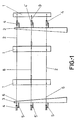
- Figure 1 - This shows a schematic view according to a side elevation of the system of the invention, according to a transmission belt formed by three cables, showing the two drag lines and the ruling cable joined to the blades according to a first embodiment in which the ruling cable may be displaced longitudinally with respect to the drag lines.
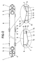
- Figure 2 - This shows a schematic plan view of the same system shown in the previous figure.
- Figure 3 - This shows, schematically, the mechanism based on which the longitudinal displacement of the ruling cable is converted to a variation of the angle of attack of the blades with respect to the direction of the wind, when the separator arms are joined in a fixed manner to the blade and articulated to the cable.
- Figure 4 - This shows, schematically, the mechanism based on which the longitudinal displacement of the ruling cable is converted into a variation of the angle of attack of the blades with respect to wind direction, in the case in which the separator arms are articulated to the blade and fixed to the cable.
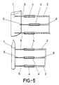
- Figure 5 - This shows a schematic view according to a side elevation of the system of the invention, according to a transmission belt consisting of three cables, showing a blade and the means of union of the latter with the two drag lines and the ruling cable, as well as the positions the pulley may occupy, which supports the ruling cable according to an embodiment in which said ruling cable may be displaced by the movement of the pulleys in a horizontal plane and the direction of the prevailing winds.
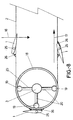
- Figure 6 - This shows a plan view of the system of the invention, according to a transmission belt consisting of three cables, according to an embodiment in which the ruling cable may be displaced by movement of the pulleys in a horizontal plane and in the direction of the prevailing winds.
- Figure 7 - This shows a schematic view according to a representation in side view of one part of the system realized according to a different embodiment, where one column of the various possibilities appears that may be included in the eolian system, on whose column are fitted two hoops guided on the corresponding pulleys and over said hoops the corresponding drag lines carrying the blades with the support and orientation system realized according to this second form of embodiment.
- Figure 8 - This shows a schematic plan view of the part of the system or installation represented in the previous figure.
- Figure 9 - This shows a detail of what could be considered a perspective of a blade with the corresponding orientation and support axis to the cables.
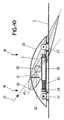
- Figure 10 - This shows a detailed view corresponding to the blade union support, across its orientation axis, to the cable, which support integrates the mechanism allowing self-orientation of the blade, in order to adopt an angle of attack smaller than the spontaneous angle when the wind speed exceeds the safety limit established for the installation.
- Figure 11 - This shows a section view of the blade, to illustrate on the same, different positions of the support axis, each one of which will result in a spontaneous angle of attack, all according to the embodiment shown in figures 7 to 10.
- Figure 12 - This shows the graph in which the relation existing between the angle of attack, the orientation axis distance from the attack edge of the blade and the driving force provided by the blade are shown.
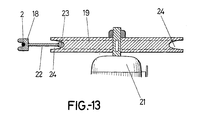
- Figure 13 - This shows, finally, a detail of the hoop guide through which the drag line runs, which hoop is guided in one or more internal wheels whose axis, in this case, corresponds to that of an alternator.
- the eolian system of the engine comprises a plurality of blades (1) arranged vertically and fastened through their internal face to a pair of drag lines (2), which run along a closed line between two columns or towers (3) arranged opposite to each other, with the particularity that these drag lines (2) determining the transmission belt pass across the corresponding pulleys (4) fitted on arms (5) which act as separators.
- the system incorporates an intermediate cable (8), called a ruling cable, to which the blades (1) are joined by their tail or exit edge by means of a mechanism constituted as from a separator arm (9) whose free end counts with a joint (10) on which a tubular component (11) is arranged internally to which a rod (12) may be displaced which, at its other end and across the joint (13), is linked to the exit edge or tail of the blade itself (1).
- a ruling cable when the ruling cable (8) is slowed down with respect to the drag lines (2), the tail of the blade (1) is pushed by the rod (12) which causes said blade (1) to rotate and as a consequence a variation in the angle formed between the latter and the transmission belt is produced.
- the ruling cable (8) intermediate between the lines (2) of the flexible transmission belt, also runs between the corresponding pulley (4') fitted over the columns (3), with the corresponding distances (5').
- the rod (12) having both an axial and an angular movement, has an elastic component (14) associated to a final run stop (15), which dampens the longitudinal displacements of the rod (12), eliminating the sudden tugs produced on changing the direction of the blades (1).
- This effect may be obtained more easily when the rod (12) is constituted by the spindle of a spring, hydraulic or pneumatic, joining the mentioned spindle in an articulated way to the tail of the blade (1), while the cylinder of the dampener is joined, also in an articulated manner to the separator arm (9) fixed to the ruling cable (8).
- the relative displacement between the ruling cable (8) and the drag lines (2) is achieved by displacing the pulley (4') over which the ruling cable (8) runs in a horizontal plane and according to the direction of the prevailing winds.
- the ruling cable (8) is joined to the blades (1), by their tail or exit edge, by means of separators (6) similar to those used for the union of the drag lines (2) to the blade (1) attack heads or edge, such that the horizontal displacement of the pulleys (4') through which the ruling cable (8) runs provokes a pushing of the separator arm (6), associated to the ruling cable (8), over the blade (1) and, as a result, a rotation of the latter with respect to the separator arms (6) associated to the drag lines (2).
- the angle formed by the blade (1) may be varied at will.
- the blades (1) may be suitably orientated to obtain the maximum performance when the wind is advantageous, it also being able to adopt a safety position when the wind strength is extremely high and may damage the system if it directly impinged on the blade (1) surface.
- the eolian system or shifting wind motor includes several blades (1) fixed over the drag lines (2), which constitute the flexible belt, the wind direction being observed in figure 8 according to the arrow (16) and the direction of line (2) movement according to the arrow (17).
- the lines (2) run through hoops (18), which are preferably fitted coaxially to the corresponding support columns (3), such that said hoops (18) are guided on wheels (19) arranged internally and foreseen at the ends of the corresponding radial arms (20) protruding from the support column (3).
- alternators (21) have been foreseen on the wheel axes (19).
- the hoops (18) will have a rim (22), finished in a rolling extension (23) which contacts with the wheel (19).
- the hoop or hoops (18) will have a throat for cable guidance (2).
- the blade profile is defined, and they may be symmetrical or of symmetric action, convex or convexo-concave or others.
- the rope and plan thereof are defined, to then determine on a testing bench the angle of attack which gives us the maximum force over the cable and the fixing point whose moment is zero for said angle of attack, hence defining the blade and its orientation axis.
- each blade (1) to the lines (2) comprising the flexible belt, is made across their orientation axis (25) and for this reason, as illustrated in figures 2 and 3, the blade will have notches (25'), cuts and other means permitting access to the axis from the union devices to the lines (2).
- Each blade (1) may freely rotate over its orientation axis (25).
- its orientation axis may be external or internal, that is, it may be in the inside or outside.
- orientation axis (25) may be continuous or discontinuous, being physically or imaginatively extended along and parallel to the blade span.
- the repeated orientation axis (25), continuous or discontinuous, is foreseen so that the blade may rotate freely with respect to the latter and, in turn, to join the blade to the drag lines by means of the support parts (26), which, first of all have some clamps (27) across which the assembly remains fastened to the cable.
- the support parts (26) is equipped with the maximum power control mechanism, consisting of a sliding part (28) to which the orientation axis is fitted (25). Said sliding part (28) may be displaced in a guide (29) statically fixed to the support (26) to which, as has been previously mentioned, across respective clamps (27) the corresponding drag line (2) is joined.
- the displacement of the sliding part (28) is exerted against the force of a spring (30), which is tared according to the maximum safety force the blade should supply to the cable.
- the maximum power control device described should exist at least in one of the support parts (26) of the union to the cables, depending on the existence of one or more parts with this device, the length or span of the blades.
- the remaining union devices of the blade to the respective cable across their orientation axis are not necessary to understand the maximum power control device, it being possible for them to be simple means of union of the cable to the orientation axis.
- the spontaneous angle of attack referred to by ( ⁇ ) will be adjusted, as shown in figure 10 and more specifically in figure 11, such that when taking into account that this spontaneous angle of attack is the angle formed by the relative wind direction, corresponding to the arrow (33) and the axis of the blade (1) itself, the relative wind being the result between the real wind component (16) and the driving power referred by (34) in figure 11. It may be verified how this spontaneous angle of attack ( ⁇ ) varies according to the position of the axis (25) with respect to the attack edge (35) of the blade (1). In figure 11 the variations of the mentioned angle ( ⁇ ) are seen or that of spontaneous attack, as well as the variation of the distance between the assembly axis (25) and the attack edge (35) of the blade (1).
- FIG 12 a diagram is shown where the interrelation existing between the axis position (25), namely, its situation with respect to the attack edge (35) of the blade, the spontaneous angle of attack ( ⁇ ) and the driving power supplied in each case, may be observed.
- This diagram corresponds to a NACA 63-015 profile, with a rope of 250 mm and for a relative speed of 22.2 m/s.
Landscapes
- Engineering & Computer Science (AREA)
- Life Sciences & Earth Sciences (AREA)
- Sustainable Development (AREA)
- Sustainable Energy (AREA)
- Chemical & Material Sciences (AREA)
- Combustion & Propulsion (AREA)
- Mechanical Engineering (AREA)
- General Engineering & Computer Science (AREA)
- Aviation & Aerospace Engineering (AREA)
- Wind Motors (AREA)
- Saccharide Compounds (AREA)
Claims (11)
- Windsysteme für die Energieerzeugung, mit mehreren Blättern (1), die in vertikaler Position in einer geschlossenen, flexiblen Übertragungslinie angebracht sind, die sich aus einer Stützstruktur aus Türmen oder Säulen (3)zusammensetzt, die die Geometrie der Übertragungslinie definiert, deren Türme oder Säulen (3) die Scheiben (4 oder 19, auf denen Kabel laufen, halten, an denen die Blätter (1) befestigt werden, dadurch gekennzeichnet, dass sie einen Mechanismus aufweisen, der es erlaubt, in kontrollierter Form den Winkel zwischen den Blättern (1) und der Übertragungslinie zu variieren, wozu jedes Blatt (1) an seinem Kopfende oder Angriffskante mit den sogenannten Schubkabeln (2) durch Abstandsstücke (6)verbunden ist, die aus an dem Blatt (1) oder Kabel (2) angelenkten Stangen bestehen, insofern die Blätter (1) mit den Lenkkabeln (8) durch ihre Enden oder Ausgangskanten derart verbunden sind, dass sich die Lenkkabel (8) bei Bremsung der sie stützenden Scheiben (4') längs verschieben können oder transversal durch die Verschiebung der genannten Scheiben (4') in einer horizontalen Ebene und damit den Blattwinkel (1) in Bezug auf den Wind ändern können.
- Windsysteme für die Energieerzeugung, nach Anspruch 1, dadurch gekennzeichnet, dass sich die Längsverschiebung hinsichtlich der Lenkkabel (8) auf die Blätter (1), über ein Zusammenspiel der an einem Ende in angelenkter Form mit dem Ende oder Ausgangskante der Blätter (1) verbundenen Stangen (12), überträgt, insofern das andere Ende in einem röhrenförmigen Element (11), das ebenfalls angelenkt an die Abstandsstücke (9) angefügt ist, ein Spiel aufweist, wobei elastische Mittel (14) zur Aufnahme von Ruckbewegungen der Stangen (12) vorgesehen sind.
- Windsysteme für die Energieerzeugung, nach den vorhergehenden Ansprüchen, dadurch gekennzeichnet, dass die Stange (12) der Schaft einer hydraulischen oder pneumatischen Feder sein kann, dessen Zylinder angelenkt mit dem Abstandsstück (9) verbunden ist.
- Windsysteme für die Energieerzeugung, nach Anspruch 1, dadurch gekennzeichnet, dass bei einer Alternativlösung der Ausführung, die Scheiben (4'), die die Lenkkabel (8) stützen, mit Mitteln zu einer horizontalen Verschiebung und in Richtung der dominierenden Winde, ausgestattet sind, insofern sich die Lenkkabel (8) über Abstandsstücke an das Ende oder die Ausgangskante der Blätter (1) anfügen, die ähnlich den Abstandsstücken sind, die die Blätter (1) mit den Schubkabeln (2) derart verbinden, dass die Verschiebung der Scheiben (4') auf denen die Lenkkabel (8) laufen, ein Anstoss der Lenkkabel (8) auf das Abstandsglied (6) bewirkt und von ihnen auf das Ende oder die Ausgangskante der Blätter (1), wobei eine Änderung der Winkelposition derselben in Bezug auf die Übertragungslinie und demzufolge bezüglich des Windes hervorgerufen wird.
- Windsysteme für die Energieerzeugung, nach den vorhergehenden Ansprüchen, dadurch gekennzeichnet, dass die Lenkung der Blätter (1) durch eine Bremskombination der Lenkscheiben (4') und der Verschiebung derselben in ihrer eigenen Ebene, erfolgen kann.
- Windsysteme für die Energieerzeugung, dadurch gekennzeichnet, dass sich die Blätter (1) über eine interne oder externe, durchgehende oder unterbrochene Ausrichtungsachse (25) halten, die parallel zur Spannweite des Blattes verläuft und sich an dem Punkt befindet, wo das Drehmoment für den grössten Angriffswinkel des Anstosses gleich Null ist, auf dessen Achse (25) sich das Blatt (1) frei dreht, um auf spontane Art und Weise den erwähnten Winkel einzunehmen, wobei vorgesehen ist, dass sich das Blatt (1) in Bezug auf die Schubkabel (2) verschieben kann, indem es die Kraft einer Feder oder elastischen Elementes überwindet und sich von dem Zeitpunkt an der Angriffswinkel nach und nach verkleinert, bis ein Gleichgewicht zwischen dem Federdruck und dem Angriffswinkel erreicht wird, das die Kraft, die das Blatt an das Kabel gibt, stabil hält.
- Windsysteme für die Energieerzeugung, nach Anspruch 6, dadurch gekennzeichnet, dass sich die Stützungspunkte der Blätter (1) an die Schubkabel (2) der Einrichtung, an Zwischenpunkten der genannten Blätter derart anordnen, dass der entsprechende Zugang durch Ausnehmungen (25'), Ausschnitte oder andere Mittel, gegeben wird.
- Windsysteme für die Energieerzeugung, nach Anspruch 6 und 7, dadurch gekennzeichnet, dass bei einer bevorzugten Ausführungsform, die Ausrichtungsachse und freie Drehung (25) der Blätter (1) mit einem gleitenden Teil (28) verbunden ist, dass in der Lage ist sich auf einer Führung (29), die Teil der Lagerung (26) ist, zu verschieben, über die sich die Einheit mit dem Schubkabel mit Hilfe von Greifern (27) verbindet, wobei vorgesehen ist, dass sich die Längsverschiebung des Gleitteils (28) und mit dieser der Achse (25) des Blattes (1) vollzieht, indem die Kraft einer Druckfeder (30) überschritten wird, bis der fest an der Achse (25) sitzende Nocken (31), mit einer Zwischenwand (32) Kontakt erhält, die ein Teil der fest mit dem Kabel (2) verbundenen Halterung (26) ist, dem Moment, an dem die Verschiebung des Nockens (31) auf der Zwischenwand (32) einen Abtrieb des Blattes (1) auslöst und, was das Gleiche ist, eine progressive Verringerung des Angriffswinkels.
- Windsysteme für die Energieerzeugung, nach Anspruch 6, dadurch gekennzeichnet, dass sich die Stellung der Ausrichtungsachse(25) des Blattes (1), aus der Auslegung des Profites und Fusspunktes des gewählten Blattes ergibt.
- Windsysteme für die Energieerzeugung, nach Anspruch 6, dadurch gekennzeichnet, dass die Stützscheiben und die Führung der Schubkabel aus Ringen (18), die sich vorzugsweise koaxial zur Stützsäule (3) befinden, zusammengesetzt sind, wobei sich jeder Ring (18)um eins oder mehrere innere Räder (19) dreht, die ihn halten, wobei die Räder (19), über aus der genannten Säule austretende Radialarme (20) mit der Stützsäule (3) verbunden sind, wobei die Achsen der Räder (18) mechanische Übertragungsachsen oder Generatoren für elektrische Energie sein können.
- Windsysteme für die Energieerzeugung, nach Anspruch 6 bis 10, dadurch gekennzeichnet, dass die Ringe (18) eine Laufrille für den Lauf des Kabels (2) und einen Radkranz (2) aufweisen, der an einer Verlängerung des Laufes (23), der mit dem Rad (19)kontaktiert, verbunden ist.
Applications Claiming Priority (5)
| Application Number | Priority Date | Filing Date | Title |
|---|---|---|---|
| ES009601832A ES2144904B1 (es) | 1996-08-22 | 1996-08-22 | Mejoras introducidas en sistemas eolicos de produccion de energia |
| ES9601832 | 1996-08-22 | ||
| ES9701824 | 1997-08-20 | ||
| ES009701824A ES2154107B1 (es) | 1997-08-20 | 1997-08-20 | Perfeccionamientos introducidos en sistemas eolicos de produccion de energia. |
| PCT/ES1997/000212 WO1998007983A1 (es) | 1996-08-22 | 1997-08-21 | Mejoras introducidas en sistemas eolicos de produccion de energia |
Publications (2)
| Publication Number | Publication Date |
|---|---|
| EP0921310A1 EP0921310A1 (de) | 1999-06-09 |
| EP0921310B1 true EP0921310B1 (de) | 2001-12-05 |
Family
ID=26154987
Family Applications (1)
| Application Number | Title | Priority Date | Filing Date |
|---|---|---|---|
| EP97935581A Expired - Lifetime EP0921310B1 (de) | 1996-08-22 | 1997-08-21 | Produktionssysteme mittels windenergie |
Country Status (8)
| Country | Link |
|---|---|
| US (1) | US6081043A (de) |
| EP (1) | EP0921310B1 (de) |
| JP (1) | JP2000516682A (de) |
| AT (1) | ATE210245T1 (de) |
| AU (1) | AU732252B2 (de) |
| CA (1) | CA2263966A1 (de) |
| DE (1) | DE69708885T2 (de) |
| WO (1) | WO1998007983A1 (de) |
Cited By (1)
| Publication number | Priority date | Publication date | Assignee | Title |
|---|---|---|---|---|
| WO2023275572A1 (en) * | 2021-06-29 | 2023-01-05 | JSC Zago Technology | Wind power plant |
Families Citing this family (19)
| Publication number | Priority date | Publication date | Assignee | Title |
|---|---|---|---|---|
| NO994893L (no) * | 1999-10-08 | 2001-04-09 | Ingvald Lie | Vindkraftmaskin |
| US6320273B1 (en) * | 2000-02-12 | 2001-11-20 | Otilio Nemec | Large vertical-axis variable-pitch wind turbine |
| US20020047274A1 (en) * | 2000-09-19 | 2002-04-25 | Williams Herbert L. | Chute type powerplant |
| KR100478753B1 (ko) * | 2002-02-21 | 2005-03-22 | 근 석 장 | 풍차 날개 |
| JP3451085B1 (ja) * | 2002-09-20 | 2003-09-29 | 常夫 野口 | 風力発電用の風車 |
| US20110042958A1 (en) * | 2007-02-27 | 2011-02-24 | Vaxsis Inc. | Collapsible vertical-axis turbine |
| WO2010030895A2 (en) * | 2008-09-11 | 2010-03-18 | Levi Avraham Y | Wind turbine |
| ITTV20080153A1 (it) * | 2008-11-25 | 2010-05-26 | Giacomo Battiston | Generatore eolico |
| NO20092798A (no) * | 2009-07-31 | 2010-10-04 | Aqua Energy Solutions As | Vannstrømkraftverk |
| JP4668349B1 (ja) * | 2010-03-29 | 2011-04-13 | エンパイア テクノロジー ディベロップメント エルエルシー | 発電システム及びセンシングシステム |
| KR100987760B1 (ko) * | 2010-04-09 | 2010-10-13 | 이지현 | 완충장치를 구비한 피치제어장치를 갖는 풍력발전기 |
| CN102183239A (zh) * | 2011-03-08 | 2011-09-14 | 西安工程大学 | 一种基于视频差异分析的输电导线风偏测量方法 |
| US9410527B2 (en) * | 2011-07-18 | 2016-08-09 | Sean N. Hsu | Tunable apparatus for generating energy from a fluid flow induced movement of a surface structure relative to a frame with at least one adjustable frame portion |
| JP2013083223A (ja) * | 2011-10-12 | 2013-05-09 | Hiroyuki Inagaki | 並進翼の迎角制御手法 |
| CN104454338A (zh) * | 2014-11-21 | 2015-03-25 | 西北工业大学 | 一种具有带轮机构的垂直轴风力发电叶轮 |
| US9777709B2 (en) * | 2015-01-08 | 2017-10-03 | Hans Dysarsz | Translating foil system for harvesting kinetic energy from wind and flowing water |
| NO338294B1 (no) * | 2015-02-05 | 2016-08-08 | Tidal Sails As | Fremgangsmåte og anlegg for utnyttelse av en vannstrømsenergi |
| TW201829908A (zh) * | 2017-02-06 | 2018-08-16 | 黃國彰 | 風力發電用葉片裝置 |
| TWI687587B (zh) * | 2018-02-05 | 2020-03-11 | 國立臺灣師範大學 | 河邊流水能之擷取裝置 |
Family Cites Families (11)
| Publication number | Priority date | Publication date | Assignee | Title |
|---|---|---|---|---|
| GB403607A (en) * | 1932-03-19 | 1933-12-28 | Marcel Vullierme | Improvements in and relating to hydraulic motors |
| US4299537A (en) * | 1979-06-19 | 1981-11-10 | Evans Frederick C | Interlinked variable-pitch blades for windmills and turbines |
| US4242050A (en) * | 1980-02-14 | 1980-12-30 | Oakes Richard M | Windmill power generator |
| US4348594A (en) * | 1980-07-14 | 1982-09-07 | Lipfert Donald E | Wind power generator |
| NL8101231A (nl) * | 1981-03-13 | 1982-10-01 | Ir Gijsbert Johannes Engelsman | Ballon-windmolen. |
| US4659940A (en) * | 1982-04-27 | 1987-04-21 | Cognitronics Corporation | Power generation from high altitude winds |
| GB2131491B (en) * | 1982-11-08 | 1986-05-08 | Roger William Bentley | Device for extracting energy from wind or water |
| US4678923A (en) * | 1985-11-13 | 1987-07-07 | Fernand Trepanier | Windmill |
| US4878807A (en) * | 1988-03-28 | 1989-11-07 | Baker Keith G | Relating to energy conversion apparatus |
| US5057696A (en) * | 1991-01-25 | 1991-10-15 | Wind Harvest Co., Inc. | Vertical windmill with omnidirectional diffusion |
| ES2113266B1 (es) * | 1994-08-05 | 1999-10-16 | Akesolo Miguel Angel Robles | Sistema eolico para produccion de energia electrica. |
-
1997
- 1997-08-21 DE DE69708885T patent/DE69708885T2/de not_active Expired - Fee Related
- 1997-08-21 AT AT97935581T patent/ATE210245T1/de not_active IP Right Cessation
- 1997-08-21 WO PCT/ES1997/000212 patent/WO1998007983A1/es not_active Ceased
- 1997-08-21 EP EP97935581A patent/EP0921310B1/de not_active Expired - Lifetime
- 1997-08-21 AU AU38515/97A patent/AU732252B2/en not_active Ceased
- 1997-08-21 CA CA002263966A patent/CA2263966A1/en not_active Abandoned
- 1997-08-21 JP JP10510446A patent/JP2000516682A/ja not_active Ceased
-
1999
- 1999-02-22 US US09/255,089 patent/US6081043A/en not_active Expired - Fee Related
Cited By (1)
| Publication number | Priority date | Publication date | Assignee | Title |
|---|---|---|---|---|
| WO2023275572A1 (en) * | 2021-06-29 | 2023-01-05 | JSC Zago Technology | Wind power plant |
Also Published As
| Publication number | Publication date |
|---|---|
| CA2263966A1 (en) | 1998-02-26 |
| DE69708885D1 (de) | 2002-01-17 |
| AU732252B2 (en) | 2001-04-12 |
| AU3851597A (en) | 1998-03-06 |
| JP2000516682A (ja) | 2000-12-12 |
| EP0921310A1 (de) | 1999-06-09 |
| WO1998007983A1 (es) | 1998-02-26 |
| DE69708885T2 (de) | 2002-08-01 |
| ATE210245T1 (de) | 2001-12-15 |
| US6081043A (en) | 2000-06-27 |
Similar Documents
| Publication | Publication Date | Title |
|---|---|---|
| EP0921310B1 (de) | Produktionssysteme mittels windenergie | |
| US4494007A (en) | Wind machine | |
| US4430044A (en) | Vertical axis wind turbine | |
| US4715776A (en) | Wind turbine system using a savonius type rotor | |
| US4423333A (en) | Horizontal axis wind energy conversion system with aerodynamic blade pitch control | |
| US9932965B2 (en) | Vertical wind generator | |
| US20080197639A1 (en) | Bi-directional wind turbine | |
| DE2851406A1 (de) | Windturbine | |
| EP0077914A1 (de) | Windkraftanlage mit mindestens einem um eine Drehachse drehbaren Flügel | |
| US8382425B2 (en) | Hydraulic energy converter | |
| US20140322013A1 (en) | Independent variable blade pitch and geometry wind turbine control | |
| US20100201132A1 (en) | Wind-driven electric plant | |
| US7118344B2 (en) | Wind power plant for generating energy | |
| US8496437B2 (en) | Power transmitting system through cables for airborne wind-type power generation applications | |
| US4303834A (en) | Cable wind mill | |
| CA2383846A1 (en) | Wind power machine | |
| EP0732500A1 (de) | Erzeugung von elektrischer energie durch wind angetriebene vorrichtung | |
| WO2005017351A1 (en) | Variable diameter rotor | |
| EP3702610B1 (de) | Vertikalachsenwindturbine mit variabler geometrie der blätter | |
| CN101230838B (zh) | 中心齿轮同步变桨距装置 | |
| CN114909258A (zh) | 一种用于降低风力机风荷载的装置 | |
| US12135006B2 (en) | Dual rotor low speed wind turbine having twisted blades | |
| DE3304825A1 (de) | Windenergieanlage | |
| DE928040C (de) | Windkraftanlage | |
| CN110678647B (zh) | 转换风能的方法和系统 |
Legal Events
| Date | Code | Title | Description |
|---|---|---|---|
| PUAI | Public reference made under article 153(3) epc to a published international application that has entered the european phase |
Free format text: ORIGINAL CODE: 0009012 |
|
| 17P | Request for examination filed |
Effective date: 19990319 |
|
| AK | Designated contracting states |
Kind code of ref document: A1 Designated state(s): AT BE CH DE DK FI FR GB GR IE IT LI LU MC NL PT SE |
|
| GRAG | Despatch of communication of intention to grant |
Free format text: ORIGINAL CODE: EPIDOS AGRA |
|
| 17Q | First examination report despatched |
Effective date: 20010223 |
|
| GRAG | Despatch of communication of intention to grant |
Free format text: ORIGINAL CODE: EPIDOS AGRA |
|
| GRAH | Despatch of communication of intention to grant a patent |
Free format text: ORIGINAL CODE: EPIDOS IGRA |
|
| GRAH | Despatch of communication of intention to grant a patent |
Free format text: ORIGINAL CODE: EPIDOS IGRA |
|
| GRAA | (expected) grant |
Free format text: ORIGINAL CODE: 0009210 |
|
| AK | Designated contracting states |
Kind code of ref document: B1 Designated state(s): AT BE CH DE DK FI FR GB GR IE IT LI LU MC NL PT SE |
|
| PG25 | Lapsed in a contracting state [announced via postgrant information from national office to epo] |
Ref country code: NL Free format text: LAPSE BECAUSE OF FAILURE TO SUBMIT A TRANSLATION OF THE DESCRIPTION OR TO PAY THE FEE WITHIN THE PRESCRIBED TIME-LIMIT Effective date: 20011205 Ref country code: LI Free format text: LAPSE BECAUSE OF FAILURE TO SUBMIT A TRANSLATION OF THE DESCRIPTION OR TO PAY THE FEE WITHIN THE PRESCRIBED TIME-LIMIT Effective date: 20011205 Ref country code: IT Free format text: LAPSE BECAUSE OF FAILURE TO SUBMIT A TRANSLATION OF THE DESCRIPTION OR TO PAY THE FEE WITHIN THE PRESCRIBED TIME-LIMIT;WARNING: LAPSES OF ITALIAN PATENTS WITH EFFECTIVE DATE BEFORE 2007 MAY HAVE OCCURRED AT ANY TIME BEFORE 2007. THE CORRECT EFFECTIVE DATE MAY BE DIFFERENT FROM THE ONE RECORDED. Effective date: 20011205 Ref country code: GR Free format text: LAPSE BECAUSE OF FAILURE TO SUBMIT A TRANSLATION OF THE DESCRIPTION OR TO PAY THE FEE WITHIN THE PRESCRIBED TIME-LIMIT Effective date: 20011205 Ref country code: FR Free format text: LAPSE BECAUSE OF FAILURE TO SUBMIT A TRANSLATION OF THE DESCRIPTION OR TO PAY THE FEE WITHIN THE PRESCRIBED TIME-LIMIT Effective date: 20011205 Ref country code: FI Free format text: LAPSE BECAUSE OF FAILURE TO SUBMIT A TRANSLATION OF THE DESCRIPTION OR TO PAY THE FEE WITHIN THE PRESCRIBED TIME-LIMIT Effective date: 20011205 Ref country code: CH Free format text: LAPSE BECAUSE OF FAILURE TO SUBMIT A TRANSLATION OF THE DESCRIPTION OR TO PAY THE FEE WITHIN THE PRESCRIBED TIME-LIMIT Effective date: 20011205 Ref country code: BE Free format text: LAPSE BECAUSE OF FAILURE TO SUBMIT A TRANSLATION OF THE DESCRIPTION OR TO PAY THE FEE WITHIN THE PRESCRIBED TIME-LIMIT Effective date: 20011205 Ref country code: AT Free format text: LAPSE BECAUSE OF FAILURE TO SUBMIT A TRANSLATION OF THE DESCRIPTION OR TO PAY THE FEE WITHIN THE PRESCRIBED TIME-LIMIT Effective date: 20011205 |
|
| REF | Corresponds to: |
Ref document number: 210245 Country of ref document: AT Date of ref document: 20011215 Kind code of ref document: T |
|
| REG | Reference to a national code |
Ref country code: CH Ref legal event code: EP |
|
| REG | Reference to a national code |
Ref country code: GB Ref legal event code: IF02 |
|
| REG | Reference to a national code |
Ref country code: IE Ref legal event code: FG4D |
|
| REF | Corresponds to: |
Ref document number: 69708885 Country of ref document: DE Date of ref document: 20020117 |
|
| PG25 | Lapsed in a contracting state [announced via postgrant information from national office to epo] |
Ref country code: SE Free format text: LAPSE BECAUSE OF FAILURE TO SUBMIT A TRANSLATION OF THE DESCRIPTION OR TO PAY THE FEE WITHIN THE PRESCRIBED TIME-LIMIT Effective date: 20020305 Ref country code: PT Free format text: LAPSE BECAUSE OF FAILURE TO SUBMIT A TRANSLATION OF THE DESCRIPTION OR TO PAY THE FEE WITHIN THE PRESCRIBED TIME-LIMIT Effective date: 20020305 Ref country code: DK Free format text: LAPSE BECAUSE OF FAILURE TO SUBMIT A TRANSLATION OF THE DESCRIPTION OR TO PAY THE FEE WITHIN THE PRESCRIBED TIME-LIMIT Effective date: 20020305 |
|
| NLV1 | Nl: lapsed or annulled due to failure to fulfill the requirements of art. 29p and 29m of the patents act | ||
| REG | Reference to a national code |
Ref country code: CH Ref legal event code: PL |
|
| PG25 | Lapsed in a contracting state [announced via postgrant information from national office to epo] |
Ref country code: LU Free format text: LAPSE BECAUSE OF NON-PAYMENT OF DUE FEES Effective date: 20020821 Ref country code: IE Free format text: LAPSE BECAUSE OF NON-PAYMENT OF DUE FEES Effective date: 20020821 |
|
| PLBE | No opposition filed within time limit |
Free format text: ORIGINAL CODE: 0009261 |
|
| STAA | Information on the status of an ep patent application or granted ep patent |
Free format text: STATUS: NO OPPOSITION FILED WITHIN TIME LIMIT |
|
| EN | Fr: translation not filed | ||
| 26N | No opposition filed | ||
| PG25 | Lapsed in a contracting state [announced via postgrant information from national office to epo] |
Ref country code: MC Free format text: LAPSE BECAUSE OF NON-PAYMENT OF DUE FEES Effective date: 20030301 |
|
| REG | Reference to a national code |
Ref country code: IE Ref legal event code: MM4A |
|
| PGFP | Annual fee paid to national office [announced via postgrant information from national office to epo] |
Ref country code: GB Payment date: 20050817 Year of fee payment: 9 |
|
| PGFP | Annual fee paid to national office [announced via postgrant information from national office to epo] |
Ref country code: DE Payment date: 20050929 Year of fee payment: 9 |
|
| PG25 | Lapsed in a contracting state [announced via postgrant information from national office to epo] |
Ref country code: DE Free format text: LAPSE BECAUSE OF NON-PAYMENT OF DUE FEES Effective date: 20070301 |
|
| GBPC | Gb: european patent ceased through non-payment of renewal fee |
Effective date: 20060821 |
|
| PG25 | Lapsed in a contracting state [announced via postgrant information from national office to epo] |
Ref country code: GB Free format text: LAPSE BECAUSE OF NON-PAYMENT OF DUE FEES Effective date: 20060821 |