EP0920810B1 - System for the production of shells of fat-containing, chocolate-like masses under pressure build-up - Google Patents
System for the production of shells of fat-containing, chocolate-like masses under pressure build-up Download PDFInfo
- Publication number
- EP0920810B1 EP0920810B1 EP98203693A EP98203693A EP0920810B1 EP 0920810 B1 EP0920810 B1 EP 0920810B1 EP 98203693 A EP98203693 A EP 98203693A EP 98203693 A EP98203693 A EP 98203693A EP 0920810 B1 EP0920810 B1 EP 0920810B1
- Authority
- EP
- European Patent Office
- Prior art keywords
- core member
- mould cavity
- mass
- chocolate
- mould
- Prior art date
- Legal status (The legal status is an assumption and is not a legal conclusion. Google has not performed a legal analysis and makes no representation as to the accuracy of the status listed.)
- Expired - Lifetime
Links
- 238000004519 manufacturing process Methods 0.000 title claims description 9
- 235000019219 chocolate Nutrition 0.000 claims description 20
- 238000000465 moulding Methods 0.000 claims description 16
- 238000003825 pressing Methods 0.000 claims description 2
- 244000299461 Theobroma cacao Species 0.000 description 18
- 239000007788 liquid Substances 0.000 description 12
- 238000000034 method Methods 0.000 description 12
- 238000001816 cooling Methods 0.000 description 8
- 239000003925 fat Substances 0.000 description 8
- 235000019197 fats Nutrition 0.000 description 8
- 239000013078 crystal Substances 0.000 description 7
- 239000000463 material Substances 0.000 description 5
- 238000000151 deposition Methods 0.000 description 4
- 238000005496 tempering Methods 0.000 description 4
- 229940110456 cocoa butter Drugs 0.000 description 3
- 235000019868 cocoa butter Nutrition 0.000 description 3
- 239000000725 suspension Substances 0.000 description 3
- 239000011248 coating agent Substances 0.000 description 2
- 238000000576 coating method Methods 0.000 description 2
- 238000002425 crystallisation Methods 0.000 description 2
- 239000003921 oil Substances 0.000 description 2
- 238000004806 packaging method and process Methods 0.000 description 2
- 239000002699 waste material Substances 0.000 description 2
- 235000009470 Theobroma cacao Nutrition 0.000 description 1
- 150000001875 compounds Chemical class 0.000 description 1
- 230000006835 compression Effects 0.000 description 1
- 238000007906 compression Methods 0.000 description 1
- 235000019221 dark chocolate Nutrition 0.000 description 1
- 235000013601 eggs Nutrition 0.000 description 1
- 235000013861 fat-free Nutrition 0.000 description 1
- 239000000796 flavoring agent Substances 0.000 description 1
- 235000019634 flavors Nutrition 0.000 description 1
- 235000013305 food Nutrition 0.000 description 1
- 238000010438 heat treatment Methods 0.000 description 1
- 235000021056 liquid food Nutrition 0.000 description 1
- 238000002844 melting Methods 0.000 description 1
- 230000008018 melting Effects 0.000 description 1
- 235000013336 milk Nutrition 0.000 description 1
- 239000008267 milk Substances 0.000 description 1
- 210000004080 milk Anatomy 0.000 description 1
- 235000019659 mouth feeling Nutrition 0.000 description 1
- XULSCZPZVQIMFM-IPZQJPLYSA-N odevixibat Chemical compound C12=CC(SC)=C(OCC(=O)N[C@@H](C(=O)N[C@@H](CC)C(O)=O)C=3C=CC(O)=CC=3)C=C2S(=O)(=O)NC(CCCC)(CCCC)CN1C1=CC=CC=C1 XULSCZPZVQIMFM-IPZQJPLYSA-N 0.000 description 1
- 239000003346 palm kernel oil Substances 0.000 description 1
- 235000019865 palm kernel oil Nutrition 0.000 description 1
- 239000002245 particle Substances 0.000 description 1
- 235000013446 pixi Nutrition 0.000 description 1
- 239000000843 powder Substances 0.000 description 1
- 238000005057 refrigeration Methods 0.000 description 1
- 239000007787 solid Substances 0.000 description 1
- 235000019222 white chocolate Nutrition 0.000 description 1
Images


Classifications
-
- A—HUMAN NECESSITIES
- A23—FOODS OR FOODSTUFFS; TREATMENT THEREOF, NOT COVERED BY OTHER CLASSES
- A23G—COCOA; COCOA PRODUCTS, e.g. CHOCOLATE; SUBSTITUTES FOR COCOA OR COCOA PRODUCTS; CONFECTIONERY; CHEWING GUM; ICE-CREAM; PREPARATION THEREOF
- A23G1/00—Cocoa; Cocoa products, e.g. chocolate; Substitutes therefor
- A23G1/04—Apparatus specially adapted for manufacture or treatment of cocoa or cocoa products
- A23G1/20—Apparatus for moulding, cutting or dispensing chocolate
- A23G1/201—Apparatus not covered by groups A23G1/21 - A23G1/28
- A23G1/205—Apparatus in which the material is shaped at least partially in a mould, in the hollows of a surface, a drum or an endless band, or by drop-by-drop casting or dispensing of the material on a surface, e.g. injection moulding or transfer moulding
- A23G1/207—Compression moulding of paste, optionally in the form of a ball, a rope or other preforms, powders or granules
-
- A—HUMAN NECESSITIES
- A23—FOODS OR FOODSTUFFS; TREATMENT THEREOF, NOT COVERED BY OTHER CLASSES
- A23G—COCOA; COCOA PRODUCTS, e.g. CHOCOLATE; SUBSTITUTES FOR COCOA OR COCOA PRODUCTS; CONFECTIONERY; CHEWING GUM; ICE-CREAM; PREPARATION THEREOF
- A23G1/00—Cocoa; Cocoa products, e.g. chocolate; Substitutes therefor
- A23G1/04—Apparatus specially adapted for manufacture or treatment of cocoa or cocoa products
- A23G1/20—Apparatus for moulding, cutting or dispensing chocolate
- A23G1/201—Apparatus not covered by groups A23G1/21 - A23G1/28
- A23G1/205—Apparatus in which the material is shaped at least partially in a mould, in the hollows of a surface, a drum or an endless band, or by drop-by-drop casting or dispensing of the material on a surface, e.g. injection moulding or transfer moulding
-
- A—HUMAN NECESSITIES
- A23—FOODS OR FOODSTUFFS; TREATMENT THEREOF, NOT COVERED BY OTHER CLASSES
- A23G—COCOA; COCOA PRODUCTS, e.g. CHOCOLATE; SUBSTITUTES FOR COCOA OR COCOA PRODUCTS; CONFECTIONERY; CHEWING GUM; ICE-CREAM; PREPARATION THEREOF
- A23G1/00—Cocoa; Cocoa products, e.g. chocolate; Substitutes therefor
- A23G1/04—Apparatus specially adapted for manufacture or treatment of cocoa or cocoa products
- A23G1/20—Apparatus for moulding, cutting or dispensing chocolate
- A23G1/21—Apparatus for moulding hollow products, open shells or other articles having cavities, e.g. open cavities
Definitions
- the present invention concerns a system for the production of fat-containing, chocolate-like masses, in particular for chocolate articles, by which an amount of liquid mass is deposited into a mould cavity, whereafter an associated core member is immersed into the mass, the temperature of which core member is being controlled.
- EP 0 589 820 A1 (AASTED-MIKROVERK APS) describes the first commercially available method and associated apparatus of the introductory type for industrial use. It relates to a method, where the chocolate-like mass under crystallisation solidifies from the mould cavity and inwardly to form the outer shape of the shell, the temperature of the mould cavity being lower than the temperature of the tempered mass, that a cooling member having a temperature lower than 0 °C is immersed into the mass and kept in the mass in a fully immersed position for a predetermined period of time. The cooling member is furthermore immersed immediately into the mass after this has been filled into the mould cavity.
- the associated apparatus furthermore comprises means of controlling the up- and down movement of the cooling members, as well as controlling residence times in the fully immersed position.
- the chocolate-mass is filled into the mould cavity in an amount, which is typically about 10% larger than the volume of the finished chocolate-shell.
- the early EP-publication teaches no means for enclosing the mould cavity at the rim of the shell, and consequently the mass rises pressureless above the upper surface of the mould plate, when a cooling member is being immersed to the fully immersed position.
- the teaching describes no means for enclosing the mould cavity fully, nor for building up pressure in the chocolate-mass during moulding.
- chocolate-like masses are suspensions of non-fat particles, such as sugar, milk powders and cocoa solids in a liquid fat phase.
- the fat phase in most cases comprises an extent of the genuin cocoa butter of until around 30 %, but may comprise substitutes as well. Such substitutes may be in the form of other types of fat-containing oils.
- Chocolate-like masses where the cocoa butter has been replaced wholely or partly by other fats are often named commercially as compound chocolate, in which the cocoa butter has been replaced by palm-kernel oil, are corresponding oils.
- the shell is frequently provided with a center mass of a creamy or liquid food material, which differs from that of the shell. Thereafter the shell is closed either with other shell parts along the periphery of the shell or by means of a coating.
- manufactured shells do not have to consist of just one layer of material but may e.g. consist of several layers of chocolate-like material.
- one shell made of dark chocolate may be provided with an interior coating of white chocolate (or vice versa) by the same method and system even before the shell moulded first leaves the mould cavity.
- the chocolate-like masses are deposited into the mould cavity in a tempered liquid state.
- chocolate-like mass being heated to 40-50 °C enters the process of tempering in which the mass in cooled down to around 27-32 °C, whereby crystallisation is initiated. Thereafter, the chocolate-like mass is re-heated, normally not more than 2 °C providing the ready-tempered chocolate-like mass with a content of stable ⁇ crystals in an amount lesser than 5 %. Thereby lower melting crystals are remelted, so that only stable crystals remain in the ready-tempered mass.
- Such a process is for example performed by the AMK-tempering machines provided by Aasted-Mikroverk ApS, Denmark.
- WO 95/32633 (AASTED-MIKROVERK APS) describes a method and a system of the introductory art, by which an engagement ring is mounted peripherally around the cooling member by a press-fit or by threaded engagement.
- the engagement ring comprises at least one peripherally extending recess defining the moulded shell rim.
- the engagement ring may be mounted axially spring-loaded by means of a rubber insert, so that when complete filling of the shell reception volume is desired, the axial travel of the engagement ring will compensate for inaccuracies in the dosing of predetermined amount of chocolate-like mass.
- the actual height of the moulded shell in question will depend upon the specific amount of chocolate being deposited for moulding that article in question. Consequently the heights of the article could not be constant and will vary from article to article depending upon variations in mass amount being deposited from article to article. Furthermore no recognition is given for providing pressure build-up during moulding of the article.
- DE 122 020 discloses a method for the production of shells of chocolate-like masses by which an amount of liquid mass is deposited into a mould cavity, whereafter an associated core member is immersed into the mass.
- a ring element closes the mould cavity upwardly and constitutes a guidance for the core member.
- the core member comprises upper peripherally extending and protruding engagement parts, which in the immersed position of the core member engage the upper surface of the ring element. By reaching that lower immersed position the liquid chocolate will consequently be squeezed out through slots between the tool parts, and in fact no pressure build-up in the mass is possible nor could be be controlled, when the core member has reached the lower position, where it stops.
- the disclosure does not give any hint to a temperature control of the core member. Therefore by the DE teaching it is not possible to compensate for varying amounts of deposited mass and at the same time keeping the height of each moulded article constant, as well as being able to control pressure build-up in the mass.
- WO 97/49296 discloses a system for the production of shells, in which former plates are rigidly connected to the forming member and thereby are the former plate and the forming member not moveable in relation to each other. It is thereby not possible for the teaching disclosed in WO 97/49296 to achieve the same height of each moulded shell and at the same time compensating for varying amount of deposited mass. The height of the shell depends on the actual amount of liquid mass deposited.
- a mould cavity closure means being axially movable in relation to the core member is extending peripherally around the core member and comprising shell rim moulding surfaces, which together with outer surfaces of the core and inner surfaces of the mould cavity determines the full geometry of the ready moulded shell, when the mould cavity closure means is in closed engagement with the mould, the core member has an unobstructed travel as well as comprising the arrangement of load means adapted to press the core member in direction against the mould cavity to achieve pressure build up in the mass.
- every moulded article has exactly the same height. Furthermore the core member is free to take in every possibly position whatever the deposited amount of chocolate-like mass may be. If the deposited amount of chocolate mass is smaller than intended, the core member will simply travel slightly further down towards the mould cavity, until complete filling of the enclosed mould cavity is obtained, the only consequence being that especially the bottom part of the article will be slightly thinner than intended. If, on the other hand, a larger amount of chocolate-like mass is deposited into the mould cavity, the travel of the core member towards the mould cavity will be lesser, so that especially the bottom part of the article will be slightly thicker than intended. By the unobstructed travel of the core member it is possible to secure pressure build-up in each article moulded, yet with the same constant height and at the same time obtaining complete filling of the mould cavity with mass.
- the density of the moulded mass material is furthermore much more uniform as by prior methods, whatever the part or geometry of the article may be. In other words every article produced has an optimal quality and properties as desired. Consequently, the waste percentage is vanishing.
- the core member may advantageously be pressed in direction against the mould cavity with a pressure force of a predetermined value.
- the pressure force transmitted to the mass being moulded may extend to as high as 100 x 10 5 N/m 2 . It has been obtained, that by raising the pressure force enhance gloss, as well as improved hardness and resistance to fat bloom is obtained for the articles. Generally without taking the type of mass into account.
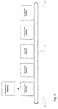
- Steps to be performed for reaching a packed shell product is schematically disclosed in fig. 1.
- an endless carrier belt 1 normally carries mould elements 2 through the depositing section, the moulding section, the cooling section, the demoulding section and finally to the packaging section. Thereafter, the endless carrier belt 1 returns the mould elements 2 to the depositing section.
- the moulding elements 2 may comprise one or even several mould cavities 3, as depicted in fig. 2 and 3.
- mould elements are moved continuously through the specific sections, such as the moulding section.
- the moulding elements may be kept stationary when the associated core members are immersed, or the core members may be moved synchronously with the mould elements within the moulding section.
- Means for achieving such movements are well known to the skilled person within the art of chocolate making.
- such systems comprise means for controlling the up and down movement of the core members as well as means for controlling the residence times of the core members in the fully immersed position, by the present invention especially to a predetermined time period.
- the residence times are typically lower than 60 seconds, though the invention is not restricted to such limitation.
- the residence times are more preferably lower than 20 seconds and are found to be especially expedient when between 0,1 and 5 seconds.
- the fat-containing, chocolate-like mass is normally tempered to a temperature of around 27-34 ° C having a content of stable ⁇ crystals.
- the tempered chocolate-like mass is delivered to the depositing section, in which the liquid mass is deposited into the mould cavity 3.
- a core member is immersed into the mass and the shell is actually moulded.
- a cooling section may follow, as well as a section for demoulding the shell from the mould, and finally a packaging section, in which the shells are packed for delivery.
- the method and the systems of the present invention are subject of the moulding section.
- the first embodiment according to the invention is disclosed in fig. 4.
- the system comprises at least one mould cavity 3 to receive the mass 5, as well as at least one associated core member 11 to be immersed into the mass 5.
- at least one associated core member 11 to be immersed into the mass 5.
- Means is arranged to control the temperature of the core member 11.
- This means could comprise well known temperature regulation devices such as a temperature measuring sensor 12 connected via a wire 13 to a control unit 14, which controls the regulation flow of a media, which circulates via channels 15 into the core member 11.
- these temperature regulation devices may be laid out in many different ways, such as comprising refrigeration or electrical heating, as long as they to the skilled person achieves an essentially constant temperature of the core member 11.
- the temperature of the core member could be controlled to be equal to or lower than 0 °C, but could even be controlled to be higher than 0 ° C.
- An especially good quality of the shells as well as fast and efficient production has been achieved, when the temperature of the core member 11 is controlled to be lower than around 10 ° C. Especially excellent results have been obtained, when the temperature of the core member is being controlled to be lower than -5 °C.
- the temperature of the mould cavity 10 may be controlled, especially to between 10 °C and 30 °C.
- the system furthermore comprises mould cavity closure means, which could be in the form of a ring 16 as depicted in fig. 4.
- the ring 16 extends peripherally around the core member 11 and comprises shell rim moulding surfaces 17, which together with outer surfaces 18 of the core 11 and inner surfaces 19 of the mould cavity 3, determines the full geometry of the ready moulded shell 6 as depicted in fig. 5.
- the cavity closure ring 16 is axially movable in relation to the core member 11. Important is, that the cavity closure ring 16 could be moved until secure closure with the mould cavity 3 when the core member 11 is moved into the mass and pressure is build-up in the mass 5. In this regard, the ring 16 may be suspended from the upper part of the core member 11 by means of one or several springs 20, or another type of compressible means.
- load means 21, 22 are arranged to press the core member 11 in direction against the mould cavity 3 to achieve pressure build-up in the mass.
- Load means may comprise a hydraulic cylinder 21, the actual load may be controlled by well known control means 22, by which it is possible to adjust the load force of the hydraulic cylinder to a predetermined value.
- a stiff frame or support 23 is disclosed, creating the necessary support of the counter pressure, when the core member 11 is immersed into the mass 5 and pressure is build-up.
- many other types of support may be arranged, as long as the hydraulic cylinder 21 as well as the mould element 10 has a proper support, when pressure is build-up in the mass.
- the core member 11 Having controlled the temperature of the core member 11 to the predetermined value, such as for example -5 °C, the core member 11 is moved downwards into the mass 5. During that movement, the mould cavity closure ring 16 engages the upper surface 24 of the mould element 10. As the ring 16 is suspended to the top part 15 of the core member 11 by a spring means 20, further downwards movement of the core 11 creates a biasing force in that spring means 20, pressing the ring 16 to a safe closure of the mould cavity 3 when the core moves further downwards.
- the predetermined value such as for example -5 °C
- the core member 11 moves even further downwards into the mass to achieve a complete filling of the enclosed mould cavity 3 with liquid mass, thereby instantaneously building up pressure in the mass.
- the travelling of the cylinder 21 is halted when the pressure-load has reached a predetermined value to be controlled and read out at the control means 22.
- the fully immersed position is disclosed in fig. 5a.
- the height of the moulded shells 6 will always be exactly the same due to the secure enclosure of the mould cavity 3 by the closure ring 16, which determines the upper position of the shell rim exactly.
- the core member 11 is free to take in every possibly position whatever the deposited amount of chocolate-like mass may be. If the deposited amount of chocolate mass is smaller than intended, the core member 11 will simply travel slightly further down towards the bottom of mould cavity 3, until complete filling of the enclosed mould cavity 3 is obtained, the only consequence being that especially the bottom part of the article 6 will be slightly thinner than intended. If, on the other hand, a larger amount of chocolate-like mass is deposited into the mould cavity than intended, the travel of the core member 11 towards the bottom of the mould cavity will be lesser, so that especially the bottom part of the article will be slightly thicker than intended. By the unobstructed travel of the core member 11 it is possible to secure pressure build-up in each article moulded, yet with the same constant height and at the same time obtaining complete filling of the mould cavity with mass.
- the density of the moulded mass material is furthermore much more uniform whatever the part or geometry of the article may be as by prior methods. In other words every article produced has a quality and properties desired. Consequently, the waste percentage is vanishing.
- the core member 26 is axially movably suspended from a holding device 27, which controls the movements of the core 26.
- the closure means constitutes part of the holding device 27.
- the core member 26 is guided axially in relation to the holding device 27 by means of a known type of slide guidance 28.
- the suspension may typically comprise compressible spring means 29 of any kind.
- a pneumatic or hydraulic pressure effected at the top surface 30 of the core member may create the appropriate suspension effect as well, either alone or in combination with the mentioned spring means 29.
- fig 6-9 may comprise a separate mould cavity closure ring 16 suspended from the holding device.
- the holding device 27 itself or the possibly intermediary closure ring comes to secure engagement with the upper surface 24 of the mould element 10 as disclosed in fig. 7.
- the core member 26 is immersed into the mass to achieve complete filling of the enclosed mould cavity thereby building up pressure in the mass, as the compression of the spring means 29 forces the core 26 in direction against the bottom of the mould cavity 3.
- the actual pressureforce obtained in the mass could be essentially the same every time when a new article is moulded. This could be done, for example by changing the numbers or actual size of a row of disc-springs or the like compressible spring means.
- the actual pressure force obtained in at the pressurised top surface of the core member is expected to be lower than 100 x 10 5 N/m 2 .
- the system comprise more than one core member 26.
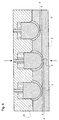
- the system comprise three core members 26 guided by the same device, and three underlying mould cavities 3, 3', 3" in a mould element 2.
- the specific numbers of mould cavities and associated core members are unlimited within this aspect of the invention.
- the holding device 27' comprises more than one core member, by which at least two are independently suspended from the holding device.
- every mould element normally always exhibits different depths of the specific mould cavities from the top surface 31 of the mould element.
- the differences may typically be up until around 1mm in deviation - plus (a) as depicted by the cavity 3' or minus (b) as depicted by the cavity 3" from the actually desired depth depicted by the cavity 3.
- Such inaccuracies in the mould elements are well-known.
- each core member 26 simply automatically adapts its immersing depth in accordance herewith always obtaining, that the specific mould cavity in question becomes completely filled out with mass.
- fig. 9. it is shown, that in the closed position of the system, the core member of the cavity 3' has moved distance a further down than the core member of the first cavity 3, and that the core member of the cavity 3" has stopped a distance b before reaching the position of the core member of the first cavity 3, yet still securing total filling of each cavity.
- a pneumatic or hydraulic pressure may advantageously be brought to the top of each core member thereby obtaining the same pressureforce for each of the shells moulded in the mould element at the same time.
- the applied pneumatic pressure could for example be lower than 10 bar.
Landscapes
- Life Sciences & Earth Sciences (AREA)
- Chemical & Material Sciences (AREA)
- Engineering & Computer Science (AREA)
- Food Science & Technology (AREA)
- Polymers & Plastics (AREA)
- Confectionery (AREA)
Description
- fig. 1
- is a schematical view of the steps performed for reaching a packed shell product,
- fig. 2
- is a schematical view of a turning point of an endless carrier for the mould elements, carried through the steps of fig. 1,
- fig. 3
- is a sectional view along A-A of the mould element of fig. 2,
- fig. 4
- is a lateral schematical cross-sectional view through a core member and an underlying mould cavity in which liquid chocolate-mass is deposited.
- fig. 5a, b
- is schematical views of the same in a closed position with the core member fully immersed in the mass and slightly retracted from the moulded shell,
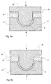
- fig. 6
- is another embodiment shown as a lateral, schematical, cross-sectional view through a core member and an underlying mould cavity filled with chocolate-mass,
- fig. 7
- is a view of the same in closed position, with the core member fully immersed into the chocolate mass,
- fig. 8
- is a lateral, schematical, cross-sectional view through a tool member, carrying several core members and an underlying mould cavity, such as the type depicted in fig. 3, which is now filled with liquid mass,
- fig. 9
- is a view of the same in a closed position.
Claims (32)
- A system for the production of shells of fat-containing, chocolate-like masses, in particular for chocolate articles,characterised in that, the systemcomprising at least one mould cavity (3; 3', 3") to receive the mass (5),at least one associated core member (11; 26) to be immersed into the mass,as well as means (12, 13, 14, 15) adapted to control the temperature of the core member,further comprising mould cavity closure means (16; 27; 27') being axially movable in relation to the core member and extending peripherally around the core member and comprising shell rim moulding surfaces (17), which together with outer surfaces (18) of the core and inner surfaces (19) of the mould cavity determines the full geometry of the ready moulded shell (6), when the mould cavity closure means is in closed engagement with the mould, the core member has an unobstructed travel,as well as comprising the arrangement of load means (21, 22; 29, 32) adapted to press the core member in direction against the mould cavity to achieve pressure build up in the mass.
- System according to claim 1, by which the load means (21, 22; 29, 32) is adapted to achieve a pressureforce of a predetermined value by pressing the core member (11; 26) in direction against the mould cavity (3; 3', 3").
- System according to claim 1, by which the load means (21, 22; 29, 32) comprise hydraulic means.
- System according to claim 1, by which the load means (21, 22; 29, 32) comprise pneumatic means.
- System according to claim 1, by which the load means (21, 22; 29) comprise spring means.
- System according to claim 1, by which the core member (11; 26) is connected to a holding device (25; 27; 27'), which controls the axial movement of the core member.
- System according to claim 6, by which the core member (11; 26) is axially movably suspended to the holding device (27; 27').
- System according to claim 1, by which load means (29; 29, 32) is adapted to actuate the pressureforce between the top (30) of the core member (11; 26) and opposite surfaces of the holding device (27; 27').
- System according to claim 1, by which the mould cavity closure means (16; 27; 27') is adapted to be forced against the upper surface (31) of the mould element (2; 10) comprising the mould cavity (3; 3', 3") in the closing position.
- System according to claim 1, by which the closure means (16) is arranged axially movable in relation to the holding device (25).
- System according to claim 1, by which spring means (20) is arranged between the closure means (16) and the holding device (25).
- System according to claim 1, by which the closure means constitutes part of the holding device (27; 27').
- System according to claim 1, by which the axial travel of the core member (11; 26) in relation to the closure means (16; 27; 27') is restricted within two extreme positions.
- System according to claim 1, by which the axial travel of the core member (11; 26) in relation to the holding device (27; 27') is restricted within two extreme positions.
- System according to claim 1, comprising more than one core member (11; 26), by which the core members are independently suspended from the holding device (27; 27').
- System according to claim 2, by which the pressureforce is lower than 100 x 105 N/m2.
- System according to claim 2, by which the pressureforce is lower than 20 x 105 N/m2.
- System according to claim 2, by which the pressureforce is between 0,1 x 10⁵ N/m2 and 10 x 105 N/m2.
- System according to claim 1, by which the core member (11; 26) is kept in the fully immersed position for a predetermined period of time, whereafter the core member is lifted out of the mass (5).
- System according to claim 19, by which the predetermined period of time is lower than 60 seconds.
- System according to claim 19, by which the predetermined period of time is lower than 20 seconds.
- System according to claim 19, by which the predetermined period of time is between 0,1 seconds and 5 seconds.
- System according to claim 2, by which the pressureforce of a predetermined value is kept at at least part of the period of keeping of the core member (11; 26) in the fully immersed position.
- System according to claim 1, by which the temperature of the core member (11; 26) is being controlled to be higher than 0 °C.
- System according to claim 1, by which the temperature of the core member (11; 26) is being controlled to be equal to or lower than 0 °C.
- System according to claim 1, by which the temperature of the core member (11; 26) is being controlled to be between -30 °C and -5°C.
- System according to claim 1, by which the pressureforce is applied directly at the top (30) op the core member (11; 26).
- System according to claim 1, by which the temperature of the mould cavity (3; 3', 3") is controlled.
- System according to claim 1, by which the temperature of the mould cavity (3; 3', 3") is controlled to be lower than the temperature of the tempered mass (5).
- System according to claim 1, by which the temperature of the mould cavity (3; 3', 3") is controlled to be between 10°C and 30 °C.
- A part of a system for the production of shells of fat-containing, chocolate-like masses, in particular for chocolate articles,
which part comprise at least one core member (11; 26) adapted to be immersed into the mass (5) in an associated mould cavity (3; 3', 3"),
characterised in that, the part of the system
further comprising mould cavity closure means (16; 27; 27') being axially movable in relation to the core member and extending peripherally around the core member and comprising shell rim surfaces (17), which together with outer surfaces (18) of the core and inner surfaces (19) of the mould cavity determines the full geometry of the ready moulded shell (6), when the mould cavity closure means is in closed engagement with the mould, the core member has an unobstructed travel. - A part according to claim 31 of a system for the production of shells of fat-containing, chocolate-like masses, in particular for chocolate articles,
which part further comprise a holding device (25; 27; 27') for the at least one core member (11; 26).
Priority Applications (18)
| Application Number | Priority Date | Filing Date | Title |
|---|---|---|---|
| DK98203693T DK0920810T3 (en) | 1998-11-02 | 1998-11-02 | System for producing shells of fat-containing, chocolate-like masses without pressure build-up |
| DE69803355T DE69803355T2 (en) | 1998-11-02 | 1998-11-02 | System for the production of trays from fatty, chocolate-like masses under pressure |
| EP98203693A EP0920810B1 (en) | 1998-11-02 | 1998-11-02 | System for the production of shells of fat-containing, chocolate-like masses under pressure build-up |
| DE0920810T DE920810T1 (en) | 1998-11-02 | 1998-11-02 | Method and device for the production of trays from fatty, chocolate-like masses under pressure |
| DK99200463T DK0925720T3 (en) | 1998-11-02 | 1999-02-19 | Apparatus comprising independently suspended piston elements for producing shells of greasy chocolate-like masses |
| DE0925720T DE925720T1 (en) | 1998-11-02 | 1999-02-19 | Device with independent suspension of the stamps for the production of trays from fatty, chocolate-like masses |
| DE69900268T DE69900268T2 (en) | 1998-11-02 | 1999-02-19 | Device with independent suspension of the stamps for the production of trays from fatty, chocolate-like masses |
| DE0923876T DE923876T1 (en) | 1998-11-02 | 1999-02-19 | Device for producing trays from fatty, chocolate-like masses |
| EP19990200463 EP0925720B1 (en) | 1998-11-02 | 1999-02-19 | Apparatus comprising independently suspended core members for the production of shells of fat-containing, chocolate-like masses |
| DE69900099T DE69900099T2 (en) | 1998-11-02 | 1999-02-19 | Device for producing trays from fatty, chocolate-like masses |
| EP19990200464 EP0923876B1 (en) | 1998-11-02 | 1999-02-19 | Apparatus for the production of shells of fat-containing, chocolate-like masses |
| DE1999201823 DE945069T1 (en) | 1998-11-02 | 1999-06-09 | Device for producing trays from fatty, chocolate-like masses |
| EP99201823A EP0945069B1 (en) | 1998-11-02 | 1999-06-09 | Apparatus for the production of shells of fat-containing, chocolate-like masses |
| DE1999600077 DE69900077T2 (en) | 1998-11-02 | 1999-06-09 | Device for producing trays from fatty, chocolate-like masses |
| US09/430,816 US6508642B1 (en) | 1998-11-02 | 1999-10-29 | Apparatus for the production of shells of fat-containing, chocolate masses |
| US09/429,971 US6497568B1 (en) | 1998-11-02 | 1999-10-29 | Apparatus for the production of shells of fat-containing chocolate-like masses under pressure build-up |
| US10/152,054 US6641386B2 (en) | 1998-11-02 | 2002-05-21 | Method and apparatus for the production of shells of fat-containing chocolate-like masses under pressure build-up |
| US10/224,251 US6644955B2 (en) | 1998-11-02 | 2002-08-20 | Method and apparatus for the production of shells of fat-containing, chocolate-like masses under pressure build-up |
Applications Claiming Priority (1)
| Application Number | Priority Date | Filing Date | Title |
|---|---|---|---|
| EP98203693A EP0920810B1 (en) | 1998-11-02 | 1998-11-02 | System for the production of shells of fat-containing, chocolate-like masses under pressure build-up |
Publications (2)
| Publication Number | Publication Date |
|---|---|
| EP0920810A1 EP0920810A1 (en) | 1999-06-09 |
| EP0920810B1 true EP0920810B1 (en) | 2002-01-02 |
Family
ID=8234286
Family Applications (1)
| Application Number | Title | Priority Date | Filing Date |
|---|---|---|---|
| EP98203693A Expired - Lifetime EP0920810B1 (en) | 1998-11-02 | 1998-11-02 | System for the production of shells of fat-containing, chocolate-like masses under pressure build-up |
Country Status (4)
| Country | Link |
|---|---|
| US (3) | US6497568B1 (en) |
| EP (1) | EP0920810B1 (en) |
| DE (6) | DE69803355T2 (en) |
| DK (2) | DK0920810T3 (en) |
Cited By (1)
| Publication number | Priority date | Publication date | Assignee | Title |
|---|---|---|---|---|
| DE102005018417B4 (en) * | 2005-04-20 | 2007-03-29 | Winkler und Dünnebier Süßwarenmaschinen GmbH | Forming station for confectionery products |
Families Citing this family (20)
| Publication number | Priority date | Publication date | Assignee | Title |
|---|---|---|---|---|
| EP1149536B1 (en) * | 2000-04-28 | 2003-09-03 | Kraft Foods R & D, Inc. Zweigniederlassung München | Chocolate production by super-cooling and press-forming |
| KR20020060512A (en) * | 2001-01-11 | 2002-07-18 | 한수길 | Process for making chocolate with the use of frozen mould |
| DE10122548A1 (en) * | 2001-05-09 | 2002-11-14 | Buehler Bindler Gmbh | Production of a bowl-shaped consumable from a fat-containing mass |
| DE10152289B4 (en) * | 2001-10-23 | 2006-03-23 | Sollich Kg | Method and device for producing a shaped body of cooked sugar mass in a mold |
| AU2003202931A1 (en) * | 2002-01-09 | 2003-07-30 | Mold-Masters Limited | Method and apparatus for measuring the temperature of molten material in a mold cavity |
| AU2003240607A1 (en) * | 2002-05-27 | 2003-12-12 | Kmb Produktions Ag | Method and device for producing confectionery products |
| DE10252633A1 (en) * | 2002-05-27 | 2003-12-11 | Kmb Produktions Ag Felben | Method and device for producing consumer goods |
| US20040035300A1 (en) * | 2002-06-27 | 2004-02-26 | Maccherone Lawrence S. | Apparatus for removing a baked article from a mold |
| DK1396191T3 (en) * | 2002-09-06 | 2004-10-25 | Aasted Mikroverk Aps | Edible pressing apparatus |
| ATE279119T1 (en) * | 2002-09-06 | 2004-10-15 | Aasted Mikroverk Aps | DEVICE FOR SHAPING EDIBLE OBJECTS |
| DE10304525A1 (en) * | 2003-02-04 | 2004-08-12 | Bühler Bindler GmbH | Manufacture of bowl-like consumables from a cocoa-based or chocolate-like fat mass |
| US7556493B2 (en) * | 2005-02-24 | 2009-07-07 | Suttle James M | Methods and apparatus for molding chocolate |
| DE202005006443U1 (en) * | 2005-04-21 | 2005-06-23 | Kmb Produktions Ag | Machine molding confectionery, especially pralines, has plate carrying molding plungers which is flexibly-mounted |
| EP1971214A1 (en) * | 2006-01-12 | 2008-09-24 | Awema Ag, | Apparatus for heating/cooling articles |
| MX2016011096A (en) | 2014-02-27 | 2016-12-16 | Hershey Co | Confectionery product and method of making. |
| GB2525668A (en) * | 2014-05-02 | 2015-11-04 | Kraft Foods R & D Inc | Improvements in and relating to production of chocolate shells |
| DE102015112735A1 (en) * | 2015-06-19 | 2016-12-22 | Kmb Produktions Ag | Method for producing a consumable product |
| ITUA20161547A1 (en) * | 2016-03-10 | 2017-09-10 | Luigi Zaini Spa | KIT AND PROCEDURE FOR THE PRODUCTION OF AN EDIBLE EGG TO BASE OF CHOCOLATE AND / OR CREAM, AND EGG SO MADE THAT |
| TR201817374A1 (en) * | 2018-11-16 | 2020-06-22 | Soelen Cikolata Gida Sanayi Ve Ticaret Anonim Sirketi | MANUFACTURING METHOD AND EQUIPMENT OF AN EDIBLE CONFECTIONERY PRODUCT IN SHELL |
| BE1027824B1 (en) * | 2019-12-06 | 2021-07-05 | Confiserie Vandenbulcke Nv | FILLED CHOCOLATE PRODUCT AND PROCEDURE FOR PRODUCING A FILLED CHOCOLATE PRODUCT |
Family Cites Families (9)
| Publication number | Priority date | Publication date | Assignee | Title |
|---|---|---|---|---|
| DE122020C (en) | ||||
| US1472229A (en) * | 1922-03-06 | 1923-10-30 | Charles A Plempel | Confection mold |
| US4426402A (en) * | 1979-04-09 | 1984-01-17 | Kaupert Gueenther | Method for rapidly producing chocolate forms |
| DE69331238D1 (en) * | 1992-02-14 | 2002-01-10 | Gradual Pty Ltd | MOLDING PROCESS AND DEVICE |
| DK172603B1 (en) * | 1992-09-23 | 1999-02-22 | Aasted Mikroverk Aps | Process and plant for making chocolate articles |
| AT401708B (en) * | 1993-06-17 | 1996-11-25 | Auer Guenter Ing | MULTI-PIECE BAKING FORM TO MAKE AN EDIBLE ICE CREAM |
| DK171697B1 (en) * | 1994-05-31 | 1997-03-24 | Aasted Mikroverk Aps | Plants for the production of shells of liquid, temperate and fatty chocolate-like mass, shells made therefrom, foodstuffs comprising said shells and the use of said shells as constituents of foodstuffs |
| AUPO066196A0 (en) * | 1996-06-25 | 1996-07-18 | Gradual Pty Ltd | Above mould moulding apparatus and method |
| DE19720844C5 (en) * | 1997-05-17 | 2004-04-01 | Kmb Produktions Ag | Method and device for producing consumables by extrusion |
-
1998
- 1998-11-02 EP EP98203693A patent/EP0920810B1/en not_active Expired - Lifetime
- 1998-11-02 DK DK98203693T patent/DK0920810T3/en active
- 1998-11-02 DE DE69803355T patent/DE69803355T2/en not_active Expired - Lifetime
- 1998-11-02 DE DE0920810T patent/DE920810T1/en active Pending
-
1999
- 1999-02-19 DE DE0923876T patent/DE923876T1/en active Pending
- 1999-02-19 DE DE69900268T patent/DE69900268T2/en not_active Expired - Lifetime
- 1999-02-19 DK DK99200463T patent/DK0925720T3/en active
- 1999-02-19 DE DE0925720T patent/DE925720T1/en active Pending
- 1999-02-19 DE DE69900099T patent/DE69900099T2/en not_active Expired - Lifetime
- 1999-10-29 US US09/429,971 patent/US6497568B1/en not_active Expired - Fee Related
-
2002
- 2002-05-21 US US10/152,054 patent/US6641386B2/en not_active Expired - Fee Related
- 2002-08-20 US US10/224,251 patent/US6644955B2/en not_active Expired - Fee Related
Cited By (2)
| Publication number | Priority date | Publication date | Assignee | Title |
|---|---|---|---|---|
| DE102005018417B4 (en) * | 2005-04-20 | 2007-03-29 | Winkler und Dünnebier Süßwarenmaschinen GmbH | Forming station for confectionery products |
| DE102005018417C5 (en) * | 2005-04-20 | 2009-02-26 | Winkler und Dünnebier Süßwarenmaschinen GmbH | Forming station for confectionery products |
Also Published As
| Publication number | Publication date |
|---|---|
| DE920810T1 (en) | 1999-10-21 |
| DE925720T1 (en) | 1999-10-21 |
| DE69900099T2 (en) | 2001-11-29 |
| US20020168457A1 (en) | 2002-11-14 |
| DE923876T1 (en) | 1999-10-21 |
| DK0925720T3 (en) | 2002-01-28 |
| US20030003210A1 (en) | 2003-01-02 |
| DE69803355D1 (en) | 2002-02-28 |
| DK0920810T3 (en) | 2002-04-22 |
| EP0920810A1 (en) | 1999-06-09 |
| US6641386B2 (en) | 2003-11-04 |
| US6644955B2 (en) | 2003-11-11 |
| DE69900268T2 (en) | 2002-06-27 |
| DE69900099D1 (en) | 2001-06-13 |
| DE69803355T2 (en) | 2002-09-19 |
| DE69900268D1 (en) | 2001-10-18 |
| US6497568B1 (en) | 2002-12-24 |
Similar Documents
| Publication | Publication Date | Title |
|---|---|---|
| EP0920810B1 (en) | System for the production of shells of fat-containing, chocolate-like masses under pressure build-up | |
| EP0914774B1 (en) | Apparatus for the production of shells of fat-containing chocolate-like masses | |
| US6508642B1 (en) | Apparatus for the production of shells of fat-containing, chocolate masses | |
| EP0925720B1 (en) | Apparatus comprising independently suspended core members for the production of shells of fat-containing, chocolate-like masses | |
| US20030232113A1 (en) | Method and apparatus for making chocolate covering layers | |
| EP1396191B1 (en) | Apparatus for pressing edible articles | |
| EP1346645B1 (en) | Apparatus for making chocolate covering layers | |
| EP1396192B1 (en) | Apparatus for pressing edible articles | |
| EP1346644B1 (en) | Method of making chocolate covering layers | |
| EP1346641B1 (en) | Method of making chocolate shells | |
| EP1346643B1 (en) | Method of making chocolate shells | |
| EP1714559B1 (en) | Apparatus for making chocolate articles on a conveyor web | |
| US20030235641A1 (en) | Method and apparatus for making chocolate shells | |
| US6938539B2 (en) | Apparatus for making chocolate articles on a conveyor web | |
| EP1346642B1 (en) | Apparatus for making chocolate shells | |
| DE69900077T2 (en) | Device for producing trays from fatty, chocolate-like masses | |
| EP1430784A1 (en) | Apparatus for pressing edible articles, such as of chocolate | |
| US6772679B2 (en) | Apparatus for making chocolate articles on a conveyor web | |
| EP2111760A1 (en) | Cold-pressing tool for chocolate mass | |
| EP1356739A1 (en) | Compression moulding of chocolate articles on a conveyor web | |
| US20040018282A1 (en) | Method and apparatus for making chocolate articles on a conveyor web |
Legal Events
| Date | Code | Title | Description |
|---|---|---|---|
| PUAI | Public reference made under article 153(3) epc to a published international application that has entered the european phase |
Free format text: ORIGINAL CODE: 0009012 |
|
| AK | Designated contracting states |
Kind code of ref document: A1 Designated state(s): BE CH DE DK FR GB IT LI NL |
|
| AX | Request for extension of the european patent |
Free format text: AL;LT;LV;MK;RO;SI |
|
| RTI1 | Title (correction) |
Free format text: METHOD AND APPARATUS FOR THE PRODUCTION OF SHELLS OF FAT-CONTAINING, CHOCOLATE-LIKE MASSES UNDER PRESSURE BUILD-UP |
|
| DET | De: translation of patent claims | ||
| 17P | Request for examination filed |
Effective date: 19991201 |
|
| AKX | Designation fees paid |
Free format text: BE CH DE DK FR GB IT LI NL |
|
| 17Q | First examination report despatched |
Effective date: 20000710 |
|
| RTI1 | Title (correction) |
Free format text: SYSTEM FOR THE PRODUCTION OF SHELLS OF FAT-CONTAINING, CHOCOLATE-LIKE MASSES UNDER PRESSURE BUILD-UP |
|
| GRAG | Despatch of communication of intention to grant |
Free format text: ORIGINAL CODE: EPIDOS AGRA |
|
| GRAG | Despatch of communication of intention to grant |
Free format text: ORIGINAL CODE: EPIDOS AGRA |
|
| GRAH | Despatch of communication of intention to grant a patent |
Free format text: ORIGINAL CODE: EPIDOS IGRA |
|
| GRAH | Despatch of communication of intention to grant a patent |
Free format text: ORIGINAL CODE: EPIDOS IGRA |
|
| GRAA | (expected) grant |
Free format text: ORIGINAL CODE: 0009210 |
|
| REG | Reference to a national code |
Ref country code: GB Ref legal event code: IF02 |
|
| AK | Designated contracting states |
Kind code of ref document: B1 Designated state(s): BE CH DE DK FR GB IT LI NL |
|
| PG25 | Lapsed in a contracting state [announced via postgrant information from national office to epo] |
Ref country code: NL Free format text: LAPSE BECAUSE OF FAILURE TO SUBMIT A TRANSLATION OF THE DESCRIPTION OR TO PAY THE FEE WITHIN THE PRESCRIBED TIME-LIMIT Effective date: 20020102 Ref country code: FR Free format text: LAPSE BECAUSE OF FAILURE TO SUBMIT A TRANSLATION OF THE DESCRIPTION OR TO PAY THE FEE WITHIN THE PRESCRIBED TIME-LIMIT Effective date: 20020102 Ref country code: BE Free format text: LAPSE BECAUSE OF FAILURE TO SUBMIT A TRANSLATION OF THE DESCRIPTION OR TO PAY THE FEE WITHIN THE PRESCRIBED TIME-LIMIT Effective date: 20020102 |
|
| REG | Reference to a national code |
Ref country code: CH Ref legal event code: NV Representative=s name: PATENTANWAELTE SCHAAD, BALASS, MENZL & PARTNER AG Ref country code: CH Ref legal event code: EP |
|
| REF | Corresponds to: |
Ref document number: 69803355 Country of ref document: DE Date of ref document: 20020228 |
|
| REG | Reference to a national code |
Ref country code: DK Ref legal event code: T3 |
|
| NLV1 | Nl: lapsed or annulled due to failure to fulfill the requirements of art. 29p and 29m of the patents act | ||
| EN | Fr: translation not filed | ||
| PLBE | No opposition filed within time limit |
Free format text: ORIGINAL CODE: 0009261 |
|
| STAA | Information on the status of an ep patent application or granted ep patent |
Free format text: STATUS: NO OPPOSITION FILED WITHIN TIME LIMIT |
|
| 26N | No opposition filed | ||
| NLV1 | Nl: lapsed or annulled due to failure to fulfill the requirements of art. 29p and 29m of the patents act | ||
| PGFP | Annual fee paid to national office [announced via postgrant information from national office to epo] |
Ref country code: GB Payment date: 20081015 Year of fee payment: 11 |
|
| GBPC | Gb: european patent ceased through non-payment of renewal fee |
Effective date: 20091102 |
|
| PG25 | Lapsed in a contracting state [announced via postgrant information from national office to epo] |
Ref country code: GB Free format text: LAPSE BECAUSE OF NON-PAYMENT OF DUE FEES Effective date: 20091102 |
|
| PGFP | Annual fee paid to national office [announced via postgrant information from national office to epo] |
Ref country code: DK Payment date: 20121130 Year of fee payment: 15 |
|
| PGFP | Annual fee paid to national office [announced via postgrant information from national office to epo] |
Ref country code: IT Payment date: 20131121 Year of fee payment: 16 |
|
| REG | Reference to a national code |
Ref country code: DK Ref legal event code: EBP Effective date: 20131130 |
|
| PG25 | Lapsed in a contracting state [announced via postgrant information from national office to epo] |
Ref country code: DK Free format text: LAPSE BECAUSE OF NON-PAYMENT OF DUE FEES Effective date: 20131130 |
|
| PG25 | Lapsed in a contracting state [announced via postgrant information from national office to epo] |
Ref country code: IT Free format text: LAPSE BECAUSE OF NON-PAYMENT OF DUE FEES Effective date: 20141102 |
|
| PGFP | Annual fee paid to national office [announced via postgrant information from national office to epo] |
Ref country code: DE Payment date: 20171108 Year of fee payment: 20 |
|
| PGFP | Annual fee paid to national office [announced via postgrant information from national office to epo] |
Ref country code: CH Payment date: 20171114 Year of fee payment: 20 |
|
| REG | Reference to a national code |
Ref country code: DE Ref legal event code: R071 Ref document number: 69803355 Country of ref document: DE |
|
| REG | Reference to a national code |
Ref country code: CH Ref legal event code: PL |