EP0920641B1 - Verfahren zur zerstörungsfreien dreidimensionalen erfassung von strukturen in bauwerken - Google Patents
Verfahren zur zerstörungsfreien dreidimensionalen erfassung von strukturen in bauwerken Download PDFInfo
- Publication number
- EP0920641B1 EP0920641B1 EP97940070A EP97940070A EP0920641B1 EP 0920641 B1 EP0920641 B1 EP 0920641B1 EP 97940070 A EP97940070 A EP 97940070A EP 97940070 A EP97940070 A EP 97940070A EP 0920641 B1 EP0920641 B1 EP 0920641B1
- Authority
- EP
- European Patent Office
- Prior art keywords
- radar
- volume
- region
- ultrasound
- scanning
- Prior art date
- Legal status (The legal status is an assumption and is not a legal conclusion. Google has not performed a legal analysis and makes no representation as to the accuracy of the status listed.)
- Expired - Lifetime
Links
Images



Classifications
-
- G—PHYSICS
- G01—MEASURING; TESTING
- G01N—INVESTIGATING OR ANALYSING MATERIALS BY DETERMINING THEIR CHEMICAL OR PHYSICAL PROPERTIES
- G01N29/00—Investigating or analysing materials by the use of ultrasonic, sonic or infrasonic waves; Visualisation of the interior of objects by transmitting ultrasonic or sonic waves through the object
- G01N29/04—Analysing solids
- G01N29/06—Visualisation of the interior, e.g. acoustic microscopy
- G01N29/0654—Imaging
- G01N29/069—Defect imaging, localisation and sizing using, e.g. time of flight diffraction [TOFD], synthetic aperture focusing technique [SAFT], Amplituden-Laufzeit-Ortskurven [ALOK] technique
-
- G—PHYSICS
- G01—MEASURING; TESTING
- G01N—INVESTIGATING OR ANALYSING MATERIALS BY DETERMINING THEIR CHEMICAL OR PHYSICAL PROPERTIES
- G01N29/00—Investigating or analysing materials by the use of ultrasonic, sonic or infrasonic waves; Visualisation of the interior of objects by transmitting ultrasonic or sonic waves through the object
- G01N29/04—Analysing solids
- G01N29/07—Analysing solids by measuring propagation velocity or propagation time of acoustic waves
-
- G—PHYSICS
- G01—MEASURING; TESTING
- G01N—INVESTIGATING OR ANALYSING MATERIALS BY DETERMINING THEIR CHEMICAL OR PHYSICAL PROPERTIES
- G01N29/00—Investigating or analysing materials by the use of ultrasonic, sonic or infrasonic waves; Visualisation of the interior of objects by transmitting ultrasonic or sonic waves through the object
- G01N29/22—Details, e.g. general constructional or apparatus details
- G01N29/26—Arrangements for orientation or scanning by relative movement of the head and the sensor
- G01N29/265—Arrangements for orientation or scanning by relative movement of the head and the sensor by moving the sensor relative to a stationary material
-
- G—PHYSICS
- G01—MEASURING; TESTING
- G01N—INVESTIGATING OR ANALYSING MATERIALS BY DETERMINING THEIR CHEMICAL OR PHYSICAL PROPERTIES
- G01N29/00—Investigating or analysing materials by the use of ultrasonic, sonic or infrasonic waves; Visualisation of the interior of objects by transmitting ultrasonic or sonic waves through the object
- G01N29/22—Details, e.g. general constructional or apparatus details
- G01N29/30—Arrangements for calibrating or comparing, e.g. with standard objects
-
- G—PHYSICS
- G01—MEASURING; TESTING
- G01S—RADIO DIRECTION-FINDING; RADIO NAVIGATION; DETERMINING DISTANCE OR VELOCITY BY USE OF RADIO WAVES; LOCATING OR PRESENCE-DETECTING BY USE OF THE REFLECTION OR RERADIATION OF RADIO WAVES; ANALOGOUS ARRANGEMENTS USING OTHER WAVES
- G01S13/00—Systems using the reflection or reradiation of radio waves, e.g. radar systems; Analogous systems using reflection or reradiation of waves whose nature or wavelength is irrelevant or unspecified
- G01S13/86—Combinations of radar systems with non-radar systems, e.g. sonar, direction finder
- G01S13/862—Combination of radar systems with sonar systems
-
- G—PHYSICS
- G01—MEASURING; TESTING
- G01S—RADIO DIRECTION-FINDING; RADIO NAVIGATION; DETERMINING DISTANCE OR VELOCITY BY USE OF RADIO WAVES; LOCATING OR PRESENCE-DETECTING BY USE OF THE REFLECTION OR RERADIATION OF RADIO WAVES; ANALOGOUS ARRANGEMENTS USING OTHER WAVES
- G01S13/00—Systems using the reflection or reradiation of radio waves, e.g. radar systems; Analogous systems using reflection or reradiation of waves whose nature or wavelength is irrelevant or unspecified
- G01S13/88—Radar or analogous systems specially adapted for specific applications
- G01S13/89—Radar or analogous systems specially adapted for specific applications for mapping or imaging
- G01S13/90—Radar or analogous systems specially adapted for specific applications for mapping or imaging using synthetic aperture techniques, e.g. synthetic aperture radar [SAR] techniques
-
- G—PHYSICS
- G01—MEASURING; TESTING
- G01S—RADIO DIRECTION-FINDING; RADIO NAVIGATION; DETERMINING DISTANCE OR VELOCITY BY USE OF RADIO WAVES; LOCATING OR PRESENCE-DETECTING BY USE OF THE REFLECTION OR RERADIATION OF RADIO WAVES; ANALOGOUS ARRANGEMENTS USING OTHER WAVES
- G01S15/00—Systems using the reflection or reradiation of acoustic waves, e.g. sonar systems
- G01S15/86—Combinations of sonar systems with lidar systems; Combinations of sonar systems with systems not using wave reflection
-
- G—PHYSICS
- G01—MEASURING; TESTING
- G01S—RADIO DIRECTION-FINDING; RADIO NAVIGATION; DETERMINING DISTANCE OR VELOCITY BY USE OF RADIO WAVES; LOCATING OR PRESENCE-DETECTING BY USE OF THE REFLECTION OR RERADIATION OF RADIO WAVES; ANALOGOUS ARRANGEMENTS USING OTHER WAVES
- G01S15/00—Systems using the reflection or reradiation of acoustic waves, e.g. sonar systems
- G01S15/88—Sonar systems specially adapted for specific applications
- G01S15/89—Sonar systems specially adapted for specific applications for mapping or imaging
-
- G—PHYSICS
- G01—MEASURING; TESTING
- G01N—INVESTIGATING OR ANALYSING MATERIALS BY DETERMINING THEIR CHEMICAL OR PHYSICAL PROPERTIES
- G01N2291/00—Indexing codes associated with group G01N29/00
- G01N2291/01—Indexing codes associated with the measuring variable
- G01N2291/011—Velocity or travel time
-
- G—PHYSICS
- G01—MEASURING; TESTING
- G01N—INVESTIGATING OR ANALYSING MATERIALS BY DETERMINING THEIR CHEMICAL OR PHYSICAL PROPERTIES
- G01N2291/00—Indexing codes associated with group G01N29/00
- G01N2291/02—Indexing codes associated with the analysed material
- G01N2291/028—Material parameters
- G01N2291/02863—Electric or magnetic parameters
-
- G—PHYSICS
- G01—MEASURING; TESTING
- G01N—INVESTIGATING OR ANALYSING MATERIALS BY DETERMINING THEIR CHEMICAL OR PHYSICAL PROPERTIES
- G01N2291/00—Indexing codes associated with group G01N29/00
- G01N2291/04—Wave modes and trajectories
- G01N2291/044—Internal reflections (echoes), e.g. on walls or defects
-
- G—PHYSICS
- G01—MEASURING; TESTING
- G01N—INVESTIGATING OR ANALYSING MATERIALS BY DETERMINING THEIR CHEMICAL OR PHYSICAL PROPERTIES
- G01N2291/00—Indexing codes associated with group G01N29/00
- G01N2291/10—Number of transducers
- G01N2291/101—Number of transducers one transducer
-
- G—PHYSICS
- G01—MEASURING; TESTING
- G01N—INVESTIGATING OR ANALYSING MATERIALS BY DETERMINING THEIR CHEMICAL OR PHYSICAL PROPERTIES
- G01N2291/00—Indexing codes associated with group G01N29/00
- G01N2291/26—Scanned objects
- G01N2291/263—Surfaces
- G01N2291/2632—Surfaces flat
-
- G—PHYSICS
- G01—MEASURING; TESTING
- G01N—INVESTIGATING OR ANALYSING MATERIALS BY DETERMINING THEIR CHEMICAL OR PHYSICAL PROPERTIES
- G01N33/00—Investigating or analysing materials by specific methods not covered by groups G01N1/00 - G01N31/00
- G01N33/38—Concrete; Lime; Mortar; Gypsum; Bricks; Ceramics; Glass
Definitions
- the invention relates to a method for non-destructive three-dimensional Detection of structures in structures, in particular made of concrete or the like Materials, according to the features specified in the preamble of claim 1.
- Such a method is known from DE-A-43 20 473, according to which the Echo signals from the far field of a single ultrasound probe can be detected are.
- the amplitudes and delay times of the echo signals are together with the position of the ultrasound probe in a storage unit as runtime location curves with associated Amplitude values can be saved. From the entirety of the transit time locus are by means of a filter device which precedes an imaging device selectable portions of the stored locus can be filtered out.
- Ultrasonic test methods regularly use sound waves in the lower frequency range The multiple reflection of sound waves is emitted and as a measured variable between a sending or receiving point and the object to be measured. In frequency representations there are significant maxima on which at Knowing the wave speeds the distance to the object can be calculated can.
- Shuckert, G Lectures and poster reports international Symposium non-destructive testing in construction, report volume 21, Berlin: DGZfP 1991, 488-504; Wüstenberg H., possibilities and concepts for ultrasonic probes especially for the construction industry "with regard to the use of ultrasound echo methods on components made of concrete suggestions for the use of an artificial Aperture has been made.
- the aim here is to replace the difficulties which when using large-area ultrasound heads arise from the movement small, comparatively simple test heads and corresponding signal processing.
- an illumination test head was attached to the underside of a concrete block coupled, using a hole a diffraction-related shadow is produced.
- the magnitude of the interferer can be determined.
- the disadvantage is that as a result noticeable phase errors can be caused by a non-constant coupling, so that those based on a phase sensitive scan Evaluation becomes uncertain.
- electromagnetic radar methods are used that are based on are based on the fact that the material to be checked has layers with different dielectric properties are present.
- Such a method is known from the publication "Symposium non-destructive testing in construction, 27.2.-1.3.91 in Berlin, Report Volume 21, Part 2, pp. 537-544 / .; Author: Dipl.-lng. C. Flohrer, Hochtief, Frankfurt / Main; Dipl.-lng. B. Bernhardt, Berlin, The location of prestressing under a multi-layer reinforced concrete reinforcement " emitted and received pulses in the frequency range between 900 MHz and 2 GHz.
- the depth information is obtained from the transit time measurement of the reflected signals, where the speed of propagation is from the speed of light in vacuum divided by the root of the average dielectric constant of the examined Material is calculated.
- Typical values for dielectric constants are, for example for concrete 7, brick 4, water 81 and iron infinite.
- the radar method uses an antenna a manipulator is continuously moved and correspondingly reaches the ultrasonic test methods which are based on the principle of the synthetic aperture. Because of these similarities, a depth-dependent representation of the examined object by lining up the recorded amplitudes be made possible. From the different transit times of the signals as well as the The material's dielectric constant becomes the depth position of the imaged Objects estimated, but the accuracy of the location is, among other things, from Moisture content of the material or dependent on cavities filled with water.
- SU-A-1 364 868 describes a method for measuring the thickness of dielectric objects known. According to this procedure, alternate electromagnetic waves and sound waves directed at the object and in Depending on the reflected energy, the thickness of the object is calculated.
- the invention is based on the object of the method of type mentioned in such a way that the accuracy of the location of structures is improved.
- the results are said to be from environment variables and Boundary conditions to be largely independent. Furthermore, the process is supposed to be realizable with as little effort as possible.
- the inventive method for non-destructive three-dimensional detection of structures is mainly used for building inspection and monitoring for use. It enables an optimal determination of wall and foundation thicknesses or of cavities in tension channels. Furthermore, the exact location of tendons, tendons and other structural elements become.
- the method according to the invention can also be used expediently location and classification of material inhomogeneities occur, in particular fine cracks, which are caused by corrosion of reinforcing bars.
- the area to be examined becomes flat scanned with both radar and sound, the high-frequency, runtime-dependent Data is recorded at every point.
- SAFT synthetic aperture focusing technique
- Layer thicknesses and optionally these layers are shown in any direction. These layers can be parallel to the measuring surface as well as perpendicular to the Measuring area can be specified. It is expediently based on "Fingerprints" performed a local calibration of the respective volume areas.
- the volume reconstruction with the special and described Integral method improves the signal-to-noise ratio.
- the data are linked with each other in any sectional plane, whereby due to the a precise analysis of the volume range was carried out based on the precise location becomes. Thus, a determination of unknown materials is based on knowledge the dielectric constant and the moisture distribution.
- the basic process sequence is to be explained in more detail with reference to FIG. 1, assigning the following functions to the individual function blocks are.
- the surface of the component to be examined is scanned and According to block 1, the scanning is first carried out using ultrasound.
- the ultrasound sensor is replaced and by a radar antenna replaced according to block 2.
- the radar antenna is also moved and detected in a grid pattern Signals from the same volume area below the scanned area.
- the Detected signals are high-frequency signals, the location of each sensor Amplitudes of the respective soil structure and their temporal form from that The distance of the structure depends on the surface. All in the Method steps 1 and 2 recorded time-dependent signals are stored in a memory 3 entered and saved.
- the stored data is used in mapping processes according to blocks 4.1 and 4.2, in particular according to the "Synthetic Aperture Focussing Technique - SAFT", the determines the respective volumetric image of the area examined, as follows is to be explained in more detail. It is expressly stated that from the examined Volume area, no two-dimensional sectional planes are shown, but one for each of the two process components sound and ground radar three-dimensional volume is calculated. It is important that according to Block 5 shows the structure of the examined area by means of sound on the The basis of differences in density and speed of sound is based on and that accordingly block 6 shows the structural representation of the examined area by means of ground radar on the dielectric constant and consequently also on the moisture distribution depends.
- a depth-dependent step is carried out Calibration of the images obtained using the two methods.
- Block 7 thus carries out an image comparison and a scale calibration based on local Fingerprints. It was recognized that in three-dimensional imaging structures which exist in the two independent imaging processes can be identified. This together with the two process components structures that are referred to as fingerprints are particularly in expediently to adapt the scales of the two figures to one another used according to the invention.
- the analysis is carried out according to block 9. This is based on the identification areas of increased sound reflection as well as on the identification of areas different dielectric constants.
- the two Physical parameters are made possible according to the invention, for example via the Scale relationship the local dielectric constant and from this the moisture of the examined floor area.
- unknown Dielectric constants are determined to draw conclusions about to draw unknown materials.
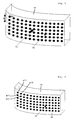
- the scanning is carried out by means of an ultrasound test head 12, which sound can both emit and receive. This takes place at predetermined positions in a first row, that is to say at positions x11, x12 ..., a second row, i.e. x21, x22, ... etc. of the concrete wall 10.
- a first row that is to say at positions x11, x12 ...
- a second row i.e. x21, x22, ... etc. of the concrete wall 10.
- the combined test head 16 is arranged in a housing 20, which with respect to the concrete surface 18 by means of a ring 22, in particular made of rubber or polystyrene combined with grease.
- a ring 22 in particular made of rubber or polystyrene combined with grease.
- Suitable channels are supplied with liquid, preferably water, via hoses 24 dissipated, only that due to the surface roughness and absorbency lost liquid / water must be replaced. It is convenient Circulatory system provided, the liquid or water with each pass is filtered.
- the scanning of the wall by means of ground radar will be explained in more detail with reference to FIG. 5 become.
- the scan by means of ground radar can in a convenient manner in the same positions as when scanning with ultrasound, but this is not a mandatory requirement.
- the relative position of all Sampling points are detected and / or saved to one another.
- a combination sensor technology is used in a particularly expedient embodiment 6 to apply to time in an advantageous manner in the data acquisition save.
- the method steps explained with reference to FIGS. 4 and 5 arrive here for use.
- the distance between the radar and the Sound sensors specified such that it multiplies the grid spacing dx by corresponds to an integer factor equal to or greater than 1. This is automatic ensures that the places of exposure from test shot to test shot for the selected Sensors match identically.
- the ultrasonic probe is in position P1 16 and the radar antenna 26 are shown with solid lines.
- the ultrasonic probe 16 and the radar antenna 26 are arranged at a distance 28 from one another.
- the ultrasonic probe is offset by the path dx. Since the respective distances dx the measuring points corresponding to positions P1 and P2 according to the invention Distance 28 of the sensors correspond, is in position P2 Ultrasonic probe at the same location as the radar antenna in position P1.
- the three-dimensional image generation of the imaging method is intended to be based on FIG corresponding to the function blocks 4.1 and 4.2 of FIG. 1 are explained in more detail.
- the three-dimensional reconstruction is expediently based on the principle of three-dimensional "synthetic aperture" performed.
- the measurement data preferably the high-frequency ultrasound and radar data saved.
- the material area to be examined / imaged is divided into small ones Disassembled volume cells. Typical orders of magnitude are in the mm or cm range.
- the distance from the measuring points to the volume cells is covered. With With the help of the speed of light and the dielectric constant ⁇ the distance for converted the ground radar into run times.
- a location-dependent one can thus be made from the amplitude values stored in terms of runtime Assignment to the volume cells concerned.
- the one to the The amplitudes belonging to the calculated runtimes are stored in the volume cells or assigned to them.
- the recorded from all measuring points Information is summed up in the volume cells in a time-corrected manner.
- the amplitude values stored in terms of runtime therefore result in a location-dependent assignment to the volume cells concerned.
- This method for the frequency range used in concrete which is in particular between 50 kHz, the probes used sound in Blast angular areas advantageously up to +/- 90 °.
- the SAFT method used according to the invention makes it possible to the influence of surface waves and mode-converted waves on the pictorial To largely suppress display. It is particularly important that regardless of the opening angle of the radar antenna or the sound, the reflective Inhomogeneities in the soil can be assigned according to location.
- the video signal is formed in the processed volume range and the result is displayed in any layer planes and layer directions.
- the reconstruction according to the principle of a special variant of the signal evaluation is given to the synthetic aperture, namely a variable proportional to the pulse energy.
- the known SAFT algorithms for each volume element to the signal intensity the corresponding point in time for each probe position An improvement the resolution and the signal-to-noise ratio will be more appropriate
- achieved by evaluating a variable proportional to the pulse energy becomes.
- for each volume element Square of the ultrasound intensity and this from the expected point of use of the echo integrated for the entire pulse duration.
- the pulse lengths on the respective Location due to frequency-dependent sound attenuation and microwave attenuation is not exactly known, is expedient in a preliminary simulation on one of the known reflectors in the volume, the pulse width in the Evaluation varies and the correct value is determined for the respective depth range.
Landscapes
- Remote Sensing (AREA)
- Engineering & Computer Science (AREA)
- Radar, Positioning & Navigation (AREA)
- Physics & Mathematics (AREA)
- General Physics & Mathematics (AREA)
- Analytical Chemistry (AREA)
- Health & Medical Sciences (AREA)
- Life Sciences & Earth Sciences (AREA)
- Chemical & Material Sciences (AREA)
- Computer Networks & Wireless Communication (AREA)
- Biochemistry (AREA)
- General Health & Medical Sciences (AREA)
- Immunology (AREA)
- Pathology (AREA)
- Acoustics & Sound (AREA)
- Electromagnetism (AREA)
- Investigating Or Analyzing Materials By The Use Of Ultrasonic Waves (AREA)
- Radar Systems Or Details Thereof (AREA)
- Measurement Of Velocity Or Position Using Acoustic Or Ultrasonic Waves (AREA)
- Investigating Or Analyzing Materials Using Thermal Means (AREA)
- Investigating Materials By The Use Of Optical Means Adapted For Particular Applications (AREA)
- Investigating Or Analyzing Materials By The Use Of Magnetic Means (AREA)
- Geophysics And Detection Of Objects (AREA)
Description
- Fig. 1
- ein Flußdiagramm zur Erläuterung der grundlegenden Verfahrensschritte,
- Fig. 2
- eine schematische Darstellung zur Erläuterung der Datenerfassung mittels Ultraschall,
- Fig. 3
- eine Variante zur Datenerfassung mittels Ultraschall,
- Fig. 4
- schematisch die Anordnung eines Prüfkopfes,
- Fig. 5
- schematisch die Anordnung zur Datenerfassung mittels Bodenradar,
- Fig. 6
- die kombinierte Anordnung von Ultraschall-Prüfkopf und Radarantenne,
- Fig. 7
- schematisch die Bilderzeugung.
- 1
- Datenerfassung mittels Ultraschall
- 2
- Datenerfassung mittels Bodenradar
- 3
- Speicher
- 4
- Abbildungsverfahren
- 5
- Strukturdarstellung unter Berücksichtigung von Dichte und Schallgeschwindigkeitsunterschieden
- 6
- Strukturdarstellung unter Berücksichtigung von Unterschieden von Dielektrizitätskonstanten
- 7
- Bildvergleich
- 8
- Bildverarbeitung
- 9
- Darstellung
- 10
- Betonwand
- 12
- Prüfkopf-Sender
- 14
- Empfänger
- 16
- kombinierter Prüfkopf
- 18
- Oberfläche
- 20
- Gehäuse
- 22
- Ring
- 24
- Schlauch
- 26
- Radarantenne
- 28
- Raster-Abstand
Claims (10)
- Verfahren zur zerstörungsfreien dreidimensionalen Erfassung von Strukturen in Bauwerken, insbesondere aus Beton oder ähnlichen Materialien, gemäß welchem der zu untersuchende Bereich flächenhaft mit Ultraschall abgetastet und die hochfrequenten laufzeitabhängigen Daten für die einzelnen Punkte aufgezeichnet werden und in einem Abbildungsverfahren das jeweilige volumenhafte Bild des untersuchten Bereiches ermittelt wird,
dadurch gekennzeichnet, daß der zu untersuchende Bereich sowohl mit Ultraschall als auch mit Radar abgetastet wird und daß eine Strukturdarstellung des untersuchten Bereiches sowohl auf der Grundlage der mittels Schall erfaßten Daten als auch auf der Grundlage der mittels Radar erfaßten Daten erfolgt und daß diese beiden Darstellungen kalibriert werden. - Verfahren nach Anspruch 1, dadurch gekennzeichnet, daß zur vorzugsweise tiefenabhängigen Kalibrierung Strukturen genutzt werden, welche sowohl in der Strukturdarstellung aufgrund der Schall-Datenerfassung als auch in der Strukturdarstellung aufgrund der Radar-Datenerfassung vorhanden sind und/oder daß mittels dieser Strukturen, welche insbesondere als Fingerprints bezeichnet und in den beiden voneinander unabhängigen Verfahrensschritten identifiziert werden, die Anpassung der Maßstäbe der beiden Darstellungen durchgeführt wird und/ oder daß anhand derartiger Strukturen bzw. Fingerprints eine örtliche Kalibrierung der jeweiligen Volumenbereiche durchgeführt wird.
- Verfahren, insbesondere nach Anspruch 1 oder 2, dadurch gekennzeichnet, daß die Abtastung mittels Schall und die Abtastung mittels Radar an den gleichen Positionen durchgeführt wird oder daß bei Abtastung an unterschiedlichen Positionen die relative Lage aller Abtastpunkte zueinander bekannt und erfaßt ist.
- Verfahren nach einem der Ansprüche 1 bis 3, dadurch gekennzeichnet, daß als Ultraschall-Abbildungsverfahren die Synthetic Aperture Focussing Technique - SAFT zum Einsatz gelangt, wobei das jeweilige volumenhafte Bild des untersuchten Bereiches berechnet wird und/oder daß ein dreidimensionales Volumen sowohl aus den mittels Ultraschall erfaßten Daten als auch aus den mittels Radar erfaßten Daten bestimmt wird.
- Verfahren nach Anspruch 4, dadurch gekennzeichnet, daß mittels des dreidimensionalen SAFT-Ultraschall-Abbildungsverfahrens ein gemeinsamer Volumenbereich bildhaft erzeugt wird und/oder daß beliebige Schichtdicken und/oder derartige Schichtdicken in vorgebbaren Richtungen darstellbar sind, wobei vorzugsweise Schichtdicken sowohl parallel zur Meßfläche als auch orthogonal zur Meßfläche darstellbar sind.
- Verfahren nach einem der Ansprüche 1 bis 5, dadurch gekennzeichnet, daß bei der Volumenrekonstruktion das Signal-Rausch-Verhältnis durch ein Integralverfahren verbessert wird und/oder daß für jedes Volumenelement das Quadrat der Ultraschall-intensität gebildet und dieses von dem erwarteten Einsatzpunkt des Echos für die gesamte Pulsdauer integriert wird.
- Verfahren nach einem der Ansprüche 1 bis 6, dadurch gekennzeichnet, daß die Daten beliebiger Schnittebenen des zu untersuchenden Bereiches erfaßt und miteinander verknüpft werden und/oder daß aufgrund einer ortsgenauen Verknüpfung eine quantitative Analyse des Volumenbereiches durchgeführt wird.
- Verfahren nach einem der Ansprüche 1 bis 7, dadurch gekennzeichnet, daß unter Berücksichtigung der Dielektrizitätskonstanten und der Feuchteverteilung unbekannte Materialien bestimmt werden.
- Verfahren nach einem der Ansprüche 1 bis 8, dadurch gekennzeichnet, daß in einer Vorabsimulation an einem bekannten Reflektor, welcher in dem Volumen vorhanden ist, die Pulsbreite in der Auswertung variiert wird und daß der für den jeweiligen Tiefenbereich zutreffende Wert der Pulslängen bestimmt wird und/oder daß somit eine frequenzabhängige Schallschwächung und/oder Mikrowellenschwächung zumindest näherungsweise kompensiert wird.
- Verfahren nach einem der Ansprüche 1 bis 9, dadurch gekennzeichnet, daß der Ultraschellsensor, mit welchem die Ultraschall-Abtastung erfolgt, und der Radarsensor, mit welchem die Radar-Abtastung erfolgt, einen Abstand aufweisen, welcher dem Einfachen oder einem Vielfachen des Rasterabstandes der Abtastposition entspricht.
Applications Claiming Priority (3)
| Application Number | Priority Date | Filing Date | Title |
|---|---|---|---|
| DE19633813 | 1996-08-22 | ||
| DE19633813A DE19633813C2 (de) | 1996-08-22 | 1996-08-22 | Verfahren zur zerstörungsfreien dreidimensionalen Erfassung von Strukturen in Bauwerken |
| PCT/EP1997/004371 WO1998008111A1 (de) | 1996-08-22 | 1997-08-12 | Verfahren zur zerstörungsfreien dreidimensionalen erfassung von strukturen in bauwerken |
Publications (2)
| Publication Number | Publication Date |
|---|---|
| EP0920641A1 EP0920641A1 (de) | 1999-06-09 |
| EP0920641B1 true EP0920641B1 (de) | 2000-10-25 |
Family
ID=7803309
Family Applications (1)
| Application Number | Title | Priority Date | Filing Date |
|---|---|---|---|
| EP97940070A Expired - Lifetime EP0920641B1 (de) | 1996-08-22 | 1997-08-12 | Verfahren zur zerstörungsfreien dreidimensionalen erfassung von strukturen in bauwerken |
Country Status (7)
| Country | Link |
|---|---|
| US (1) | US6186006B1 (de) |
| EP (1) | EP0920641B1 (de) |
| AT (1) | ATE197193T1 (de) |
| DE (2) | DE19633813C2 (de) |
| ES (1) | ES2152700T3 (de) |
| PT (1) | PT920641E (de) |
| WO (1) | WO1998008111A1 (de) |
Families Citing this family (23)
| Publication number | Priority date | Publication date | Assignee | Title |
|---|---|---|---|---|
| NL1015460C2 (nl) * | 2000-06-16 | 2001-12-19 | Kema Nv | Werkwijze voor het onderzoeken van scheuren in steenachtig materiaal. |
| WO2002001219A1 (en) * | 2000-06-29 | 2002-01-03 | Peeze Binkhorst, Ignatius, Aloysius, Gerardus, Maria | Method and apparatus for determination of the adhesion of layers of repair mortar to concrete constructions |
| CA2411632C (en) | 2000-07-14 | 2013-09-17 | Lockheed Martin Corporation | System and method for locating and positioning an ultrasonic signal generator for testing purposes |
| AU2007200013B2 (en) * | 2000-07-14 | 2010-01-21 | Lockheed Martin Corporation | System and method for locating and positioning an ultrasonic signal generator for testing purposes |
| DE10050655C1 (de) * | 2000-10-13 | 2002-01-24 | Hilti Ag | GPR-Mehrfachantennen-Vorrichtung zur Materialerkundung für den kombinierten Einsatz mit einem Handwerkzeug |
| DE10102577C1 (de) * | 2001-01-20 | 2002-06-20 | Univ Braunschweig Tech | Verfahren zur Zustandserkennung von elektrisch leitfähigen länglichen Spanngliedern |
| US6533099B2 (en) * | 2001-03-14 | 2003-03-18 | Hytrol Conveyor Company, Inc. | Article sorting system and method |
| US7301497B2 (en) * | 2005-04-05 | 2007-11-27 | Eastman Kodak Company | Stereo display for position sensing systems |
| DE102006027132B4 (de) * | 2006-06-02 | 2010-04-15 | BAM Bundesanstalt für Materialforschung und -prüfung | Verfahren zum Detektieren von Fehlstellen in Betonbauteilen |
| DE102006029435A1 (de) | 2006-06-20 | 2008-01-10 | BAM Bundesanstalt für Materialforschung und -prüfung | Vorrichtung zur zerstörungsfreien Prüfung von Bauteilen |
| US8290303B2 (en) * | 2007-10-11 | 2012-10-16 | General Electric Company | Enhanced system and method for volume based registration |
| US7548192B1 (en) * | 2008-02-07 | 2009-06-16 | Fdh Engineering, Inc. | Method of mapping steel reinforcements in concrete foundations |
| US9177371B2 (en) * | 2008-06-09 | 2015-11-03 | Siemens Energy, Inc. | Non-destructive examination data visualization and analysis |
| DE102009039716B3 (de) * | 2009-08-28 | 2011-01-20 | Ruprecht-Karls-Universität Heidelberg | Messverfahren zur zerstörungsfreien Analyse einer Schneebeschichtung und Messvorrichtung zur Durchführung des Messverfahrens |
| CN103018339A (zh) * | 2011-09-22 | 2013-04-03 | 北京理工大学 | 一种高速高精度的超声显微扫查装置 |
| US9075098B2 (en) * | 2013-01-16 | 2015-07-07 | Thomas Michael Schurman | Plug-in electric vehicle charger validation and test device |
| US9041408B2 (en) * | 2013-01-16 | 2015-05-26 | Hrl Laboratories, Llc | Removable surface-wave networks for in-situ material health monitoring |
| US20150203303A1 (en) | 2014-01-21 | 2015-07-23 | Howard Eisenberg | Device for reliably moving article from conveyor surface |
| US9436783B2 (en) | 2013-03-01 | 2016-09-06 | Simco Technologies Inc. | Method and system for estimating degradation and durability of concrete structures and asset management system making use of same |
| RU2657314C1 (ru) * | 2017-08-28 | 2018-06-13 | Российская Федерация в лице общества с ограниченной ответственностью "Акустические Контрольные Системы" | Способ определения акустической плотности |
| CN109946380B (zh) * | 2019-04-03 | 2022-09-27 | 石家庄铁道大学 | 无砟轨道砂浆层脱空检测方法、装置及终端设备 |
| CN111323485A (zh) * | 2020-04-09 | 2020-06-23 | 上海工程技术大学 | 一种用于轨道板内部缺陷检测的成像方法及装置 |
| CN112834621B (zh) * | 2020-12-31 | 2024-07-23 | 安徽理工大学 | 一种基于超声波技术的岩体裂隙三维重构方法 |
Family Cites Families (10)
| Publication number | Priority date | Publication date | Assignee | Title |
|---|---|---|---|---|
| JPS5961791A (ja) * | 1982-09-30 | 1984-04-09 | Japan Radio Co Ltd | Crt表示装置 |
| JPS62201382A (ja) * | 1986-02-28 | 1987-09-05 | Shipbuild Res Assoc Japan | 自船位置自動補正装置付航法装置 |
| US5005147A (en) * | 1988-12-30 | 1991-04-02 | The United States Of America As Represented By The Administrator, The National Aeronautics And Space Administration | Method and apparatus for sensor fusion |
| JPH04242186A (ja) * | 1991-01-12 | 1992-08-28 | Seiko Electronic Components Ltd | 航行援助システム |
| US5384543A (en) * | 1992-11-09 | 1995-01-24 | Martin Marietta Energy Systems, Inc. | Portable microwave instrument for non-destructive evaluation of structural characteristics |
| DE4239221A1 (de) * | 1992-11-21 | 1994-05-26 | Otto Dr Rer Nat Kroggel | Ultraschallreflexions-Verfahren zur Trennrißerkennung in Stahlbeton |
| US5495576A (en) * | 1993-01-11 | 1996-02-27 | Ritchey; Kurtis J. | Panoramic image based virtual reality/telepresence audio-visual system and method |
| US5774091A (en) * | 1993-04-12 | 1998-06-30 | The Regents Of The University Of California | Short range micro-power impulse radar with high resolution swept range gate with damped transmit and receive cavities |
| DE4320473C2 (de) * | 1993-06-21 | 1995-04-13 | Fraunhofer Ges Forschung | Ultraschallprüfvorrichtung |
| US5805098A (en) * | 1996-11-01 | 1998-09-08 | The United States Of America As Represented By The Secretary Of The Army | Method and system for forming image by backprojection |
-
1996
- 1996-08-22 DE DE19633813A patent/DE19633813C2/de not_active Expired - Fee Related
-
1997
- 1997-08-12 EP EP97940070A patent/EP0920641B1/de not_active Expired - Lifetime
- 1997-08-12 PT PT97940070T patent/PT920641E/pt unknown
- 1997-08-12 DE DE59702543T patent/DE59702543D1/de not_active Expired - Lifetime
- 1997-08-12 ES ES97940070T patent/ES2152700T3/es not_active Expired - Lifetime
- 1997-08-12 US US09/214,829 patent/US6186006B1/en not_active Expired - Lifetime
- 1997-08-12 WO PCT/EP1997/004371 patent/WO1998008111A1/de not_active Ceased
- 1997-08-12 AT AT97940070T patent/ATE197193T1/de active
Also Published As
| Publication number | Publication date |
|---|---|
| DE19633813A1 (de) | 1998-02-26 |
| ES2152700T3 (es) | 2001-02-01 |
| US6186006B1 (en) | 2001-02-13 |
| ATE197193T1 (de) | 2000-11-15 |
| PT920641E (pt) | 2001-03-30 |
| DE59702543D1 (de) | 2000-11-30 |
| DE19633813C2 (de) | 1998-07-02 |
| WO1998008111A1 (de) | 1998-02-26 |
| EP0920641A1 (de) | 1999-06-09 |
Similar Documents
| Publication | Publication Date | Title |
|---|---|---|
| DE19633813C2 (de) | Verfahren zur zerstörungsfreien dreidimensionalen Erfassung von Strukturen in Bauwerken | |
| EP1979739B1 (de) | Verfahren zur zerstörungsfreien untersuchung eines wenigstens einen akustisch anisotropen werkstoffbereich aufweisenden prüfkörpers | |
| EP2024740B1 (de) | Verfahren zum detektieren und klassifizieren von fehlstellen in bauteilen mittels ultraschall | |
| DE69509882T2 (de) | Verfahren und gerät zur auswertung und charakterisierung von knocheneigenschaften | |
| DE69022562T2 (de) | Verbessertes Sonarsystem für Ozeanboden. | |
| DE69128466T2 (de) | Verfahren und Vorrichtung für frequenzselektive Ultraschallprüfung von mehrschichtigen Strukturen | |
| EP0021196B1 (de) | Verfahren und Anordnung zur zerstörungsfreien Werkstoffprüfung mit Ultraschallimpulsen und Anordnung zur Durchführung des Verfahrens | |
| EP2062040B1 (de) | Verfahren und vorrichtung zur zerstörungsfreien prüfkörperuntersuchung mittels ultraschall längs einer prüfkörperoberfläche | |
| EP2032978B1 (de) | Ultraschall-prüfgerät mit array-prüfköpfen | |
| DE102005051781A1 (de) | Verfahren zur zerstörungsfreien Untersuchung eines Prüfkörpers mittels Ultraschall | |
| DE60215406T2 (de) | Verfahren und Vorrichtung zur Ultraschallabbildung | |
| DE69801181T2 (de) | Verfahren und Vorrichtung zur Verarbeitung von aus einer Volumenstruktur übertragenen oder gebeugten Signalen reflektierter Wellen zur Erkundung oder Analyse der Struktur | |
| DE102018001731A1 (de) | Verfahren zur Ermittlung zumindest eines physikalischen Parameters eines Systems unter Ausnutzung der Reflexion von einem Referenzobjekt | |
| EP1943509B1 (de) | Verfahren und vorrichtung zur bildgebenden ultraschallprüfung an eine dreidimensionalen werkstück | |
| DE3927308C2 (de) | ||
| DE69705900T2 (de) | Verfahren und Anordnung zur Bearbeitung von Signalen, welche durch ein Volumenstruktur reflektierte oder übertragene Wellen darstellen, um eine Forschung und Analyse der Struktur auszuführen | |
| DE69515444T2 (de) | Verfahren zum Entdecken von Gegenständen in der Bodenfläche oder zum Bestimmen der Ausbreitungsmerkmale einer akustischen Welle im Boden und Vorrichtung dafür | |
| DE102005041390A1 (de) | Verfahren zum Erzeugen eines Sonarbildes | |
| DE3889252T2 (de) | Ultraschall-Echographiegerät mit mindestens einem, mit einem Zufallsphase-Schirm verbundenen, piezoelektrischen Wandler und Verfahren zur Untersuchung eines Mediums mittels eines solchen Echographiegerätes. | |
| DE69204719T2 (de) | Verfahren zur Auswahl von Ultraschallwandlern. | |
| DE102009042970A1 (de) | Verfahren und Vorrichtung zum Vermessen eines Bodenprofils | |
| DE4022152C2 (de) | ||
| DE102012109257B4 (de) | Verfahren und Vorrichtung zur Erzeugung eines Ultraschallbildes | |
| DE19929708B4 (de) | Verfahren zur Gewinnung von bodenrelevanten Parametern bei der Sedimentortung mit parametrischen akustischen Schallquellen | |
| DE102019116142A1 (de) | Vorrichtung zur tomografischen Ultraschallprüfung einer Innenstruktur einer Metallbramme und Verfahren zur in-situ Qualitätsprüfung von Metallbrammen |
Legal Events
| Date | Code | Title | Description |
|---|---|---|---|
| PUAI | Public reference made under article 153(3) epc to a published international application that has entered the european phase |
Free format text: ORIGINAL CODE: 0009012 |
|
| 17P | Request for examination filed |
Effective date: 19980604 |
|
| AK | Designated contracting states |
Kind code of ref document: A1 Designated state(s): AT BE CH DE ES FR GB IT LI LU PT |
|
| GRAG | Despatch of communication of intention to grant |
Free format text: ORIGINAL CODE: EPIDOS AGRA |
|
| 17Q | First examination report despatched |
Effective date: 19991108 |
|
| GRAG | Despatch of communication of intention to grant |
Free format text: ORIGINAL CODE: EPIDOS AGRA |
|
| GRAH | Despatch of communication of intention to grant a patent |
Free format text: ORIGINAL CODE: EPIDOS IGRA |
|
| ITF | It: translation for a ep patent filed | ||
| GRAH | Despatch of communication of intention to grant a patent |
Free format text: ORIGINAL CODE: EPIDOS IGRA |
|
| GRAA | (expected) grant |
Free format text: ORIGINAL CODE: 0009210 |
|
| AK | Designated contracting states |
Kind code of ref document: B1 Designated state(s): AT BE CH DE ES FR GB IT LI LU PT |
|
| REF | Corresponds to: |
Ref document number: 197193 Country of ref document: AT Date of ref document: 20001115 Kind code of ref document: T |
|
| REG | Reference to a national code |
Ref country code: CH Ref legal event code: EP |
|
| GBT | Gb: translation of ep patent filed (gb section 77(6)(a)/1977) |
Effective date: 20001025 |
|
| ET | Fr: translation filed | ||
| REF | Corresponds to: |
Ref document number: 59702543 Country of ref document: DE Date of ref document: 20001130 |
|
| REG | Reference to a national code |
Ref country code: ES Ref legal event code: FG2A Ref document number: 2152700 Country of ref document: ES Kind code of ref document: T3 |
|
| REG | Reference to a national code |
Ref country code: PT Ref legal event code: SC4A Free format text: AVAILABILITY OF NATIONAL TRANSLATION Effective date: 20001221 |
|
| PLBE | No opposition filed within time limit |
Free format text: ORIGINAL CODE: 0009261 |
|
| STAA | Information on the status of an ep patent application or granted ep patent |
Free format text: STATUS: NO OPPOSITION FILED WITHIN TIME LIMIT |
|
| 26N | No opposition filed | ||
| REG | Reference to a national code |
Ref country code: GB Ref legal event code: IF02 |
|
| REG | Reference to a national code |
Ref country code: CH Ref legal event code: PFA Owner name: FRAUNHOFER-GESELLSCHAFT ZUR FOERDERUNG DER ANGEWA Free format text: FRAUNHOFER-GESELLSCHAFT ZUR FOERDERUNG DER ANGEWANDTEN FORSCHUNG E.V.#LEONRODSTRASSE 54#80636 MUENCHEN (DE) -TRANSFER TO- FRAUNHOFER-GESELLSCHAFT ZUR FOERDERUNG DER ANGEWANDTEN FORSCHUNG E.V.#HANSASTRASSE 27 C#80686 MUENCHEN (DE) |
|
| REG | Reference to a national code |
Ref country code: DE Ref legal event code: R082 Ref document number: 59702543 Ref country code: DE Ref legal event code: R082 Ref document number: 59702543 Country of ref document: DE Representative=s name: , |
|
| REG | Reference to a national code |
Ref country code: DE Ref legal event code: R084 Ref document number: 59702543 Country of ref document: DE Effective date: 20130311 |
|
| PGFP | Annual fee paid to national office [announced via postgrant information from national office to epo] |
Ref country code: LU Payment date: 20130826 Year of fee payment: 17 |
|
| PGFP | Annual fee paid to national office [announced via postgrant information from national office to epo] |
Ref country code: CH Payment date: 20130826 Year of fee payment: 17 Ref country code: ES Payment date: 20130828 Year of fee payment: 17 Ref country code: AT Payment date: 20130821 Year of fee payment: 17 Ref country code: PT Payment date: 20130212 Year of fee payment: 17 |
|
| PGFP | Annual fee paid to national office [announced via postgrant information from national office to epo] |
Ref country code: GB Payment date: 20130823 Year of fee payment: 17 Ref country code: FR Payment date: 20130820 Year of fee payment: 17 |
|
| PGFP | Annual fee paid to national office [announced via postgrant information from national office to epo] |
Ref country code: IT Payment date: 20130826 Year of fee payment: 17 |
|
| PGFP | Annual fee paid to national office [announced via postgrant information from national office to epo] |
Ref country code: BE Payment date: 20130821 Year of fee payment: 17 |
|
| PGFP | Annual fee paid to national office [announced via postgrant information from national office to epo] |
Ref country code: DE Payment date: 20140821 Year of fee payment: 18 |
|
| REG | Reference to a national code |
Ref country code: PT Ref legal event code: MM4A Free format text: LAPSE DUE TO NON-PAYMENT OF FEES Effective date: 20150212 |
|
| PG25 | Lapsed in a contracting state [announced via postgrant information from national office to epo] |
Ref country code: LU Free format text: LAPSE BECAUSE OF NON-PAYMENT OF DUE FEES Effective date: 20140812 |
|
| REG | Reference to a national code |
Ref country code: CH Ref legal event code: PL |
|
| REG | Reference to a national code |
Ref country code: AT Ref legal event code: MM01 Ref document number: 197193 Country of ref document: AT Kind code of ref document: T Effective date: 20140812 |
|
| GBPC | Gb: european patent ceased through non-payment of renewal fee |
Effective date: 20140812 |
|
| PG25 | Lapsed in a contracting state [announced via postgrant information from national office to epo] |
Ref country code: LI Free format text: LAPSE BECAUSE OF NON-PAYMENT OF DUE FEES Effective date: 20140831 Ref country code: CH Free format text: LAPSE BECAUSE OF NON-PAYMENT OF DUE FEES Effective date: 20140831 Ref country code: IT Free format text: LAPSE BECAUSE OF NON-PAYMENT OF DUE FEES Effective date: 20140812 Ref country code: BE Free format text: LAPSE BECAUSE OF NON-PAYMENT OF DUE FEES Effective date: 20140831 Ref country code: PT Free format text: LAPSE BECAUSE OF NON-PAYMENT OF DUE FEES Effective date: 20150212 |
|
| PG25 | Lapsed in a contracting state [announced via postgrant information from national office to epo] |
Ref country code: AT Free format text: LAPSE BECAUSE OF NON-PAYMENT OF DUE FEES Effective date: 20140812 |
|
| REG | Reference to a national code |
Ref country code: FR Ref legal event code: ST Effective date: 20150430 |
|
| PG25 | Lapsed in a contracting state [announced via postgrant information from national office to epo] |
Ref country code: GB Free format text: LAPSE BECAUSE OF NON-PAYMENT OF DUE FEES Effective date: 20140812 |
|
| PG25 | Lapsed in a contracting state [announced via postgrant information from national office to epo] |
Ref country code: FR Free format text: LAPSE BECAUSE OF NON-PAYMENT OF DUE FEES Effective date: 20140901 |
|
| REG | Reference to a national code |
Ref country code: ES Ref legal event code: FD2A Effective date: 20150925 |
|
| PG25 | Lapsed in a contracting state [announced via postgrant information from national office to epo] |
Ref country code: ES Free format text: LAPSE BECAUSE OF NON-PAYMENT OF DUE FEES Effective date: 20140813 |
|
| REG | Reference to a national code |
Ref country code: DE Ref legal event code: R119 Ref document number: 59702543 Country of ref document: DE |
|
| PG25 | Lapsed in a contracting state [announced via postgrant information from national office to epo] |
Ref country code: DE Free format text: LAPSE BECAUSE OF NON-PAYMENT OF DUE FEES Effective date: 20160301 |