EP0920202A2 - Verfahren, Speicherplatte und Vorrichtung zur Kodierung einer nahtlosen Verbindung für in Fernsehfilm umgesetzte Videodaten - Google Patents
Verfahren, Speicherplatte und Vorrichtung zur Kodierung einer nahtlosen Verbindung für in Fernsehfilm umgesetzte Videodaten Download PDFInfo
- Publication number
- EP0920202A2 EP0920202A2 EP19990102251 EP99102251A EP0920202A2 EP 0920202 A2 EP0920202 A2 EP 0920202A2 EP 19990102251 EP19990102251 EP 19990102251 EP 99102251 A EP99102251 A EP 99102251A EP 0920202 A2 EP0920202 A2 EP 0920202A2
- Authority
- EP
- European Patent Office
- Prior art keywords
- video
- data
- vob
- stream
- field
- Prior art date
- Legal status (The legal status is an assumption and is not a legal conclusion. Google has not performed a legal analysis and makes no representation as to the accuracy of the status listed.)
- Ceased
Links
Images


Classifications
-
- H—ELECTRICITY
- H04—ELECTRIC COMMUNICATION TECHNIQUE
- H04N—PICTORIAL COMMUNICATION, e.g. TELEVISION
- H04N5/00—Details of television systems
- H04N5/76—Television signal recording
- H04N5/91—Television signal processing therefor
- H04N5/92—Transformation of the television signal for recording, e.g. modulation, frequency changing; Inverse transformation for playback
-
- G—PHYSICS
- G11—INFORMATION STORAGE
- G11B—INFORMATION STORAGE BASED ON RELATIVE MOVEMENT BETWEEN RECORD CARRIER AND TRANSDUCER
- G11B20/00—Signal processing not specific to the method of recording or reproducing; Circuits therefor
- G11B20/10—Digital recording or reproducing
-
- G—PHYSICS
- G11—INFORMATION STORAGE
- G11B—INFORMATION STORAGE BASED ON RELATIVE MOVEMENT BETWEEN RECORD CARRIER AND TRANSDUCER
- G11B27/00—Editing; Indexing; Addressing; Timing or synchronising; Monitoring; Measuring tape travel
- G11B27/10—Indexing; Addressing; Timing or synchronising; Measuring tape travel
- G11B27/102—Programmed access in sequence to addressed parts of tracks of operating record carriers
- G11B27/105—Programmed access in sequence to addressed parts of tracks of operating record carriers of operating discs
-
- G—PHYSICS
- G11—INFORMATION STORAGE
- G11B—INFORMATION STORAGE BASED ON RELATIVE MOVEMENT BETWEEN RECORD CARRIER AND TRANSDUCER
- G11B27/00—Editing; Indexing; Addressing; Timing or synchronising; Monitoring; Measuring tape travel
- G11B27/10—Indexing; Addressing; Timing or synchronising; Measuring tape travel
- G11B27/19—Indexing; Addressing; Timing or synchronising; Measuring tape travel by using information detectable on the record carrier
- G11B27/28—Indexing; Addressing; Timing or synchronising; Measuring tape travel by using information detectable on the record carrier by using information signals recorded by the same method as the main recording
- G11B27/30—Indexing; Addressing; Timing or synchronising; Measuring tape travel by using information detectable on the record carrier by using information signals recorded by the same method as the main recording on the same track as the main recording
- G11B27/3027—Indexing; Addressing; Timing or synchronising; Measuring tape travel by using information detectable on the record carrier by using information signals recorded by the same method as the main recording on the same track as the main recording used signal is digitally coded
-
- G—PHYSICS
- G11—INFORMATION STORAGE
- G11B—INFORMATION STORAGE BASED ON RELATIVE MOVEMENT BETWEEN RECORD CARRIER AND TRANSDUCER
- G11B27/00—Editing; Indexing; Addressing; Timing or synchronising; Monitoring; Measuring tape travel
- G11B27/10—Indexing; Addressing; Timing or synchronising; Measuring tape travel
- G11B27/19—Indexing; Addressing; Timing or synchronising; Measuring tape travel by using information detectable on the record carrier
- G11B27/28—Indexing; Addressing; Timing or synchronising; Measuring tape travel by using information detectable on the record carrier by using information signals recorded by the same method as the main recording
- G11B27/32—Indexing; Addressing; Timing or synchronising; Measuring tape travel by using information detectable on the record carrier by using information signals recorded by the same method as the main recording on separate auxiliary tracks of the same or an auxiliary record carrier
- G11B27/327—Table of contents
- G11B27/329—Table of contents on a disc [VTOC]
-
- H—ELECTRICITY
- H04—ELECTRIC COMMUNICATION TECHNIQUE
- H04N—PICTORIAL COMMUNICATION, e.g. TELEVISION
- H04N9/00—Details of colour television systems
- H04N9/79—Processing of colour television signals in connection with recording
- H04N9/80—Transformation of the television signal for recording, e.g. modulation, frequency changing; Inverse transformation for playback
- H04N9/804—Transformation of the television signal for recording, e.g. modulation, frequency changing; Inverse transformation for playback involving pulse code modulation of the colour picture signal components
- H04N9/8042—Transformation of the television signal for recording, e.g. modulation, frequency changing; Inverse transformation for playback involving pulse code modulation of the colour picture signal components involving data reduction
-
- G—PHYSICS
- G11—INFORMATION STORAGE
- G11B—INFORMATION STORAGE BASED ON RELATIVE MOVEMENT BETWEEN RECORD CARRIER AND TRANSDUCER
- G11B2220/00—Record carriers by type
- G11B2220/20—Disc-shaped record carriers
- G11B2220/25—Disc-shaped record carriers characterised in that the disc is based on a specific recording technology
- G11B2220/2537—Optical discs
- G11B2220/2562—DVDs [digital versatile discs]; Digital video discs; MMCDs; HDCDs
-
- G—PHYSICS
- G11—INFORMATION STORAGE
- G11B—INFORMATION STORAGE BASED ON RELATIVE MOVEMENT BETWEEN RECORD CARRIER AND TRANSDUCER
- G11B27/00—Editing; Indexing; Addressing; Timing or synchronising; Monitoring; Measuring tape travel
- G11B27/02—Editing, e.g. varying the order of information signals recorded on, or reproduced from, record carriers
- G11B27/031—Electronic editing of digitised analogue information signals, e.g. audio or video signals
- G11B27/034—Electronic editing of digitised analogue information signals, e.g. audio or video signals on discs
-
- H—ELECTRICITY
- H04—ELECTRIC COMMUNICATION TECHNIQUE
- H04N—PICTORIAL COMMUNICATION, e.g. TELEVISION
- H04N5/00—Details of television systems
- H04N5/76—Television signal recording
- H04N5/84—Television signal recording using optical recording
- H04N5/85—Television signal recording using optical recording on discs or drums
-
- H—ELECTRICITY
- H04—ELECTRIC COMMUNICATION TECHNIQUE
- H04N—PICTORIAL COMMUNICATION, e.g. TELEVISION
- H04N9/00—Details of colour television systems
- H04N9/79—Processing of colour television signals in connection with recording
- H04N9/80—Transformation of the television signal for recording, e.g. modulation, frequency changing; Inverse transformation for playback
- H04N9/804—Transformation of the television signal for recording, e.g. modulation, frequency changing; Inverse transformation for playback involving pulse code modulation of the colour picture signal components
- H04N9/806—Transformation of the television signal for recording, e.g. modulation, frequency changing; Inverse transformation for playback involving pulse code modulation of the colour picture signal components with processing of the sound signal
- H04N9/8063—Transformation of the television signal for recording, e.g. modulation, frequency changing; Inverse transformation for playback involving pulse code modulation of the colour picture signal components with processing of the sound signal using time division multiplex of the PCM audio and PCM video signals
-
- H—ELECTRICITY
- H04—ELECTRIC COMMUNICATION TECHNIQUE
- H04N—PICTORIAL COMMUNICATION, e.g. TELEVISION
- H04N9/00—Details of colour television systems
- H04N9/79—Processing of colour television signals in connection with recording
- H04N9/80—Transformation of the television signal for recording, e.g. modulation, frequency changing; Inverse transformation for playback
- H04N9/82—Transformation of the television signal for recording, e.g. modulation, frequency changing; Inverse transformation for playback the individual colour picture signal components being recorded simultaneously only
- H04N9/8205—Transformation of the television signal for recording, e.g. modulation, frequency changing; Inverse transformation for playback the individual colour picture signal components being recorded simultaneously only involving the multiplexing of an additional signal and the colour video signal
Definitions
- the present invention relates to a method and apparatus for encoding telecine-converted video data for seamless connection and , more particularly to a bitstream for use in an authoring system for variously processing a data bitstream comprising the video data, audio data, and sub-picture data constituting each of plural program titles containing related video data, audio data, and sub-picture data content to generate a bitstream from which a new title containing the content desired by the user can be reproduced, and efficiently recording and reproducing said generated bitstream using a particular recording medium.
- Video-CDs in particular are able to record video data to a CD format disk, which was originally designed with an approximately 600 MB recording capacity for storing digital audio data only, by using such high efficiency video compression techniques as MPEG.
- MPEG high efficiency video compression techniques
- karaoke titles and other conventional laser disk applications are gradually being transferred to the video CD format.
- each title must be composed from bitstreams with an increasingly deep hierarchical structure.
- the data size of multimedia titles written with bitstreams having such deep hierarchical structures is ten or more times greater than the data size of less complex titles.
- the need to edit small image (title) details also makes it necessary to process and control the bitstream using low order hierarchical data units.
- One way to increase the storage capacity of the optical disk is to reduce the spot diameter D of the optical (laser) beam. If the wavelength of the laser beam is l and the aperture of the objective lens is NA, then the spot diameter D is proportional to l/NA, and the storage capacity can be efficiently improved by decreasing l and increasing NA.
- tilt coma caused by a relative tilt between the disk surface and the optical axis of the laser beam
- NA optical axis of the laser beam
- tilt-induced coma the transparent substrate must be made very thin. The problem is that the mechanical strength of the disk is low when the transparent substrate is very thin.
- MPEG1 the conventional method of recording and reproducing video, audio, and graphic signal data
- MPEG2 the more robust MPEG2 method, which can transfer large data volumes at a higher rate.
- the compression method and data format of the MPEG2 standard differ somewhat from those of MPEG1.
- the specific content of and differences between MPEG1 and MPEG2 are described in detail in the ISO-11172 and ISO-13818 MPEG standards, and further description thereof is omitted below.
- the object of the present invention is to provide an effective authoring system for controlling a multimedia data bitstream with advanced hardware and software requirements using a data unit smaller than the title to better address advanced user requirements.
- “Tele-cinema” conversion basically accomplishes the frame rate conversion by inserting at a regular period a redundant field copying a field with the same parity. Because there is not a simple integer ratio between the film frame rate and video frame rate, a conversion pattern that differs from the normal pattern is inserted to the gaps in this regular insertion process. When the resulting tele-cine converted signal is then compression coded, the copied redundant fields will also be coded if compression coding is applied at the video frame rate. Coding redundant field information is obviously inefficient. As a result, compression coding is applied after a reverse tele-cine conversion process whereby the copied redundant fields are detected and removed. In this case, a flag indicating whether a redundant field has been removed, and a flag defining the presentation order of the two fields in the frame, are both recorded with each frame.
- the object of the present invention is to provide a data structure whereby seamless reproduction can be achieved even at cell borders without the bottom fields from two connected frames or the top fields from two connected frames being connected when video objects VOB are seamlessly reproduced; a method for generating a system stream having said data structure; a recording apparatus and a reproduction apparatus for recording and reproducing said system stream; and an optical disk medium and optical disk recording method for recording said system stream.
- the present invention has been developed with a view to substantially solving the above described disadvantages and has for its essential object to provide an seamless encoding method for telecine-converted video data.
- a signal conversion recording method applies a signal recording method whereby a video signal converted to a frame rate greater than the frame rate of the signal source by repeating particular fields plural times is converted to an intermediate signal having a frame rate substantially equal to the frame rate of the original signal source by deleting these repeated redundant fields, this intermediate signal is compression coded to obtain the recording signal, and the recording signal is recorded to a recording medium together with a repeat first field flag RFF declaring whether a field was deleted, and a top field first flag TFF declaring which of the two fields in the each of the resulting frames is first on the time-base, wherein when plural logical recording periods are provided on a single recording medium, said video signal is converted to the recording signal so that said flags hold particular values at the start and end of each recording period.
- one title refers to the combination of video and audio data expressing program content recognized by a user for education, entertainment, or other purpose.
- Referenced to a motion picture (movie) one title may correspond to the content of an entire movie, or to just one scene within said movie.
- a video title set comprises the bitstream data containing the information for a specific number of titles. More specifically, each VTS comprises the video, audio, and other reproduction data representing the content of each title in the set, and control data for controlling the content data.
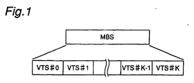
- the video zone VZ is the video data unit processed by the authoring system, and comprises a specific number of video title sets. More specifically, each video zone is a linear sequence of K + 1 video title sets numbered VTS #0 - VTS #K where K is an integer value of zero or greater.
- One video title set preferably the first video title set VTS #0, is used as the video manager describing the content information of the titles contained in each video title set.
- the multimedia bitstream MBS is the largest control unit of the multimedia data bitstream handled by the authoring system of the present invention, and comprises plural video zones VZ.
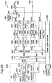
- FIG. 2 A preferred embodiment of the authoring encoder EC according to the present invention for generating a new multimedia bitstream MBS by re-encoding the original multimedia bitstream MBS according to the scenario desired by the user is shown in Fig. 2.
- the original multimedia bitstream MBS comprises a video stream St1 containing the video information, a sub-picture stream St3 containing caption text and other auxiliary video information, and the audio stream St5 containing the audio information.
- the video and audio streams are the bitstreams containing the video and audio information obtained from the source within a particular period of time.
- the sub-picture stream is a bitstream containing momentary video information relevant to a particular scene.
- the sub-picture data encoded to a single scene may be captured to video memory and displayed continuously from the video memory for plural scenes as may be necessary.
- this multimedia source data St1, St3, and St5 is obtained from a live broadcast
- the video and audio signals are supplied in real-time from a video camera or other imaging source; when the multimedia source data is reproduced from a video tape or other recording medium, the audio and video signals are not real-time signals.
- multimedia source stream is shown in Fig. 2 as comprising these three source signals, this is for convenience only, and it should be noted that the multimedia source stream may contain more than three types of source signals, and may contain source data for different titles. Multimedia source data with audio, video, and sub-picture data for plural titles are referred to below as multi-title streams.
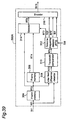
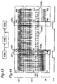
- the authoring encoder EC comprises a scenario editor 100, encoding system controller 200, video encoder 300, video stream buffer 400, sub-picture encoder 500, sub-picture stream buffer 600, audio encoder 700, audio stream buffer 800, system encoder 900, video zone formatter 1300, recorder 1200, and recording medium M.
- the video zone formatter 1300 comprises video object (VOB) buffer 1000, formatter 1100, and volume and file structure formatter 1400.
- VOB video object
- the bitstream encoded by the authoring encoder EC of the present embodiment is recorded by way of example only to an optical disk.
- the scenario editor 100 of the authoring encoder EC outputs the scenario data, i.e., the user-defined editing instructions.
- the scenario data controls editing the corresponding parts of the multimedia bitstream MBS according to the user's manipulation of the video, sub-picture, and audio components of the original multimedia title.
- This scenario editor 100 preferably comprises a display, speaker(s), keyboard, CPU, and source stream buffer.
- the scenario editor 100 is connected to an external multimedia bitstream source from which the multimedia source data St1, St3, and St5 are supplied.
- the user is thus able to reproduce the video and audio components of the multimedia source data using the display and speaker to confirm the content of the generated title.
- the user is then able to edit the title content according to the desired scenario using the keyboard, mouse, and other command input devices while confirming the content of the title on the display and speakers.
- the result of this multimedia data manipulation is the scenario data St7.
- the scenario data St7 is basically a set of instructions describing what source data is selected from all or a subset of the source data containing plural titles within a defined time period, and how the selected source data is reassembled to reproduce the scenario (sequence) intended by the user.
- the CPU codes the position, length, and the relative time-based positions of the edited parts of the respective multimedia source data streams St1, St3, and St5 to generate the scenario data St7.
- the source stream buffer has a specific capacity, and is used to delay the multimedia source data streams St1, St3, and St5 a known time Td and then output streams St1, St3, and St5.
- This delay is required for synchronization with the editor encoding process. More specifically, when data encoding and user generation of scenario data St7 are executed simultaneously, i.e., when encoding immediately follows editing, time Td is required to determine the content of the multimedia source data editing process based on the scenario data St7 as will be described further below. As a result, the multimedia source data must be delayed by time Td to synchronize the editing process during the actual encoding operation. Because this delay time Td is limited to the time required to synchronize the operation of the various system components in the case of sequential editing as described above, the source stream buffer is normally achieved by means of a high speed storage medium such as semiconductor memory.
- the source stream buffer may be a low speed, high capacity storage medium such as video tape, magnetic disk, or optical disk.
- the structure (type) of media used for the source stream buffer may therefore be determined according to the delay time Td required and the allowable manufacturing cost.
- the encoding system controller 200 is connected to the scenario editor 100 and receives the scenario data St7 therefrom. Based on the time-base position and length information of the edit segment contained in the scenario data St7, the encoding system controller 200 generates the encoding parameter signals St9, St11, and St13 for encoding the edit segment of the multimedia source data.
- the encoding signals St9, St11, and St13 supply the parameters used for video, sub-picture, and audio encoding, including the encoding start and end timing.
- multimedia source data St1, St3, and St5 are output after delay time Td by the source stream buffer, and are therefore synchronized to encoding parameter signals St9, St11, and St13.
- encoding parameter signal St9 is the video encoding signal specifying the encoding timing of video stream St1 to extract the encoding segment from the video stream St1 and generate the video encoding unit.
- Encoding parameter signal St11 is likewise the sub-picture stream encoding signal used to generate the sub-picture encoding unit by specifying the encoding timing for sub-picture stream St3.
- Encoding parameter signal St13 is the audio encoding signal used to generate the audio encoding unit by specifying the encoding timing for audio stream St5.
- the encoding system controller 200 Based on the time-base relationship between the encoding segments of streams St1, St3, and St5 in the multimedia source data contained in scenario data St7, the encoding system controller 200 generates the timing signals St21, St23, and St25 arranging the encoded multimedia-encoded stream in the specified time-base relationship.
- the encoding system controller 200 also generates the reproduction time information IT defining the reproduction time of the title editing unit (video object, VOB), and the stream encoding data St33 defining the system encode parameters for multiplexing the encoded multimedia stream containing video, audio, and sub-picture data. Note that the reproduction time information IT and stream encoding data St33 are generated for the video object VOB of each title in one video zone VZ.
- the encoding system controller 200 also generates the title sequence control signal St39, which declares the formatting parameters for formatting the title editing units VOB of each of the streams in a particular time-base relationship as a multimedia bitstream. More specifically, the title sequence control signal St39 is used to control the connections between the title editing units (VOB) of each title in the multimedia bitstream MBS, or to control the sequence of the interleaved title editing unit (VOBs) interleaving the title editing units VOB of plural reproduction paths.
- VOB title editing units
- VOBs interleaved title editing unit
- the video encoder 300 is connected to the source stream buffer of the scenario editor 100 and to the encoding system controller 200, and receives therefrom the video stream St1 and video encoding parameter signal St9, respectively.
- Encoding parameters supplied by the video encoding signal St9 include the encoding start and end timing, bit rate, the encoding conditions for the encoding start and end, and the material type. Possible material types include NTSC or PAL video signal, and telecine converted material.
- the video encoder 300 Based on the video encoding parameter signal St9, the video encoder 300 encodes a specific part of the video stream St1 to generate the encoded video stream St15.
- the sub-picture encoder 500 is similarly connected to the source stream buffer of the scenario editor 100 and to the encoding system controller 200, and receives therefrom the sub-picture stream St3 and sub-picture encoding parameter signal St11, respectively. Based on the sub-picture encoding parameter signal St11, the sub-picture encoder 500 encodes a specific part of the sub-picture stream St3 to generate the encoded sub-picture stream St17.
- the audio encoder 700 is also connected to the source stream buffer of the scenario editor 100 and to the encoding system controller 200, and receives therefrom the audio stream St5 and audio encoding parameter signal St13, which supplies the encoding start and end timing. Based on the audio encoding parameter signal St13, the audio encoder 700 encodes a specific part of the audio stream St5 to generate the encoded audio stream St19.
- the video stream buffer 400 is connected to the video encoder 300 and to the encoding system controller 200.
- the video stream buffer 400 stores the encoded video stream St15 input from the video encoder 300, and outputs the stored encoded video stream St15 as the time-delayed encoded video stream St27 based on the timing signal St21 supplied from the encoding system controller 200.
- the sub-picture stream buffer 600 is similarly connected to the sub-picture encoder 500 and to the encoding system controller 200.
- the sub-picture stream buffer 600 stores the encoded sub-picture stream St17 output from the sub-picture encoder 500, and then outputs the stored encoded sub-picture stream St17 as time-delayed encoded sub-picture stream St29 based on the timing signal St23 supplied from the encoding system controller 200.
- the audio stream buffer 800 is similarly connected to the audio encoder 700 and to the encoding system controller 200.
- the audio stream buffer 800 stores the encoded audio stream St19 input from the audio encoder 700, and then outputs the encoded audio stream St19 as the time-delayed encoded audio stream St31 based on the timing signal St25 supplied from the encoding system controller 200.
- the system encoder 900 is connected to the video stream buffer 400, sub-picture stream buffer 600, audio stream buffer 800, and the encoding system controller 200, and is respectively supplied thereby with the time-delayed encoded video stream St27, time-delayed encoded sub-picture stream St29, time-delayed encoded audio stream St31, and the stream encoding data St33.
- the system encoder 900 is a multiplexer that multiplexes the time-delayed streams St27, St29, and St31 based on the stream encoding data St33 (timing signal) to generate title editing unit (VOB) St35.
- the stream encoding data St33 contains the system encoding parameters, including the encoding start and end timing.
- the video zone formatter 1300 is connected to the system encoder 900 and the encoding system controller 200 from which the title editing unit (VOB) St35 and title sequence control signal St39 (timing signal) are respectively supplied.
- the title sequence control signal St39 contains the formatting start and end timing, and the formatting parameters used to generate (format) a multimedia bitstream MBS.
- the video zone formatter 1300 rearranges the title editing units (VOB) St35 in one video zone VZ in the scenario sequence defined by the user based on the title sequence control signal St39 to generate the edited multimedia stream data St43.
- the multimedia bitstream MBS St43 edited according to the user-defined scenario is then sent to the recorder 1200.
- the recorder 1200 processes the edited multimedia stream data St43 to the data stream St45 format of the recording medium M, and thus records the formatted data stream St45 to the recording medium M.
- the multimedia bitstream MBS recorded to the recording medium M contains the volume file structure VFS, which includes the physical address of the data on the recording medium generated by the video zone formatter 1300.
- the encoded multimedia bitstream MBS St35 may be output directly to the decoder to immediately reproduce the edited title content. It will be obvious that the output multimedia bitstream MBS will not in this case contain the volume file structure VFS.
- a preferred embodiment of the authoring decoder DC used to decode the multimedia bitstream MBS edited by the authoring encoder EC of the present invention, and thereby reproduce the content of each title unit according to the user-defined scenario, is described next below with reference to Fig. 3. Note that in the preferred embodiment described below the multimedia bitstream St45 encoded by the authoring encoder EC is recorded to the recording medium M.
- the authoring decoder DC comprises a multimedia bitstream producer 2000, scenario selector 2100, decoding system controller 2300, stream buffer 2400, system decoder 2500, video buffer 2600, sub-picture buffer 2700, audio buffer 2800, synchronizer 2900, video decoder 3800, sub-picture decoder 3100, audio decoder 3200, synthesizer 3500, video data output terminal 3600, and audio data output terminal 3700.
- the bitstream producer 2000 comprises a recording media drive unit 2004 for driving the recording medium M; a reading head 2006 for reading the information recorded to the recording medium M and producing the binary read signal St57; a signal processor 2008 for variously processing the read signal St57 to generate the reproduced bitstream St61; and a reproduction controller 2002.
- the reproduction controller 2002 is connected to the decoding system controller 2300 from which the multimedia bitstream reproduction control signal St53 is supplied, and in turn generates the reproduction control signals St55 and St59 respectively controlling the recording media drive unit (motor) 2004 and signal processor 2008.
- the authoring decoder DC comprises a scenario selector 2100 for selecting and reproducing the corresponding scenes (titles).
- the scenario selector 2100 then outputs the selected titles as scenario data to the authoring decoder DC.
- the scenario selector 2100 preferably comprises a keyboard, CPU, and monitor. Using the keyboard, the user then inputs the desired scenario based on the content of the scenario input by the authoring encoder EC. Based on the keyboard input, the CPU generates the scenario selection data St51 specifying the selected scenario.
- the scenario selector 2100 is connected by an infrared communications device, for example, to the decoding system controller 2300, to which it inputs the scenario selection data St51.
- the decoding system controller 2300 Based on the scenario selection data St51, the decoding system controller 2300 then generates the bitstream reproduction control signal St53 controlling the operation of the bitstream producer 2000.
- the stream buffer 2400 has a specific buffer capacity used to temporarily store the reproduced bitstream St61 input from the bitstream producer 2000, extract the address information and initial synchronization data SCR (system clock reference) for each stream, and generate bitstream control data St63.
- the stream buffer 2400 is also connected to the decoding system controller 2300, to which it supplies the generated bitstream control data St63.
- the synchronizer 2900 is connected to the decoding system controller 2300 from which it receives the system clock reference SCR contained in the synchronization control data St81 to set the internal system clock STC and supply the reset system clock St79 to the decoding system controller 2300.
- the decoding system controller 2300 Based on this system clock St79, the decoding system controller 2300 also generates the stream read signal St65 at a specific interval and outputs the read signal St65 to the stream buffer 2400.
- the stream buffer 2400 Based on the supplied read signal St65, the stream buffer 2400 outputs the reproduced bitstream St61 at a specific interval to the system decoder 2500 as bitstream St67.
- the decoding system controller 2300 Based on the scenario selection data St51, the decoding system controller 2300 generates the decoding signal St69 defining the stream Ids for the video, sub-picture, and audio bitstreams corresponding to the selected scenario, and outputs to the system decoder 2500.
- the system decoder 2500 respectively outputs the video, sub-picture, and audio bitstreams input from the stream buffer 2400 to the video buffer 2600, sub-picture buffer 2700, and audio buffer 2800 as the encoded video stream St71, encoded sub-picture stream St73, and encoded audio stream St75.
- the system decoder 2500 detects the presentation time stamp PTS and decoding time stamp DTS of the smallest control unit in each bitstream St67 to generate the time information signal St77.
- This time information signal St77 is supplied to the synchronizer 2900 through the decoding system controller 2300 as the synchronization control data St81.
- the synchronizer 2900 determines the decoding start timing whereby each of the bitstreams will be arranged in the correct sequence after decoding, and then generates and inputs the video stream decoding start signal St89 to the video decoder 3800 based on this decoding timing.
- the synchronizer 2900 also generates and supplies the sub-picture decoding start signal St91 and audio stream decoding start signal St93 to the sub-picture decoder 3100 and audio decoder 3200, respectively.
- the video decoder 3800 generates the video output request signal St84 based on the video stream decoding start signal St89, and outputs to the video buffer 2600.
- the video buffer 2600 outputs the video stream St83 to the video decoder 3800.
- the video decoder 3800 thus detects the presentation time information contained in the video stream St83, and disables the video output request signal St84 when the length of the received video stream St83 is equivalent to the specified presentation time.
- a video stream equal in length to the specified presentation time is thus decoded by the video decoder 3800, which outputs the reproduced video signal St104 to the synthesizer 3500.
- the sub-picture decoder 3100 similarly generates the sub-picture output request signal St86 based on the sub-picture decoding start signal St91, and outputs to the sub-picture buffer 2700.
- the sub-picture buffer 2700 outputs the sub-picture stream St85 to the sub-picture decoder 3100.
- the sub-picture decoder 3100 decodes a length of the sub-picture stream St85 corresponding to the specified presentation time to reproduce and supply to the synthesizer 3500 the sub-picture signal St99.
- the synthesizer 3500 superimposes the video signal St104 and sub-picture signal St99 to generate and output the multi-picture video signal St105 to the video data output terminal 3600.
- the audio decoder 3200 generates and supplies to the audio buffer 2800 the audio output request signal St88 based on the audio stream decoding start signal St93.
- the audio buffer 2800 thus outputs the audio stream St87 to the audio decoder 3200.
- the audio decoder 3200 decodes a length of the audio stream St87 corresponding to the specified presentation time based on the presentation time information contained in the audio stream St87, and outputs the decoded audio stream St101 to the audio data output terminal 3700.
- the authoring decoder DC is able to reproduce the title content desired by the user in the desired sequence by reproducing the multimedia bitstream MBS corresponding to the selected scenario.
- the multimedia bitstream thus encoded can then be reproduced according to the one scenario selected from among plural possible scenarios. It is also possible to change scenarios while playback is in progress, i.e., to select a different scenario and dynamically generate a new multimedia bitstream according to the most recently selected scenario. It is also possible to dynamically select and reproduce any of plural scenes while reproducing the title content according to a desired scenario.
- FIG. 4 An example of a digital video disk (DVD) with only one recording surface (a single-sided DVD) is shown in Fig. 4.
- the DVD recording medium RC1 in the preferred embodiment of the invention comprises a data recording surface RS1 to and from which data is written and read by emitting laser beam LS, and a protective layer PL1 covering the data recording surface RS1.
- a backing layer BL1 is also provided on the back of data recording surface RS1.
- the side of the disk on which protective layer PL1 is provided is therefore referred to below as side SA (commonly "side A"), and the opposite side (on which the backing layer BL1 is provided) is referred to as side SB ("side B").
- side SA commonly "side A"
- side SB side B
- digital video disk recording media having a single data recording surface RS1 on only one side such as this DVD recording medium RC1 is commonly called a single-sided single layer disk.
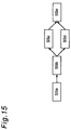
- FIG. 5 A detailed illustration of area C1 in Fig. 4 is shown in Fig. 5.
- the data recording surface RS1 is formed by applying a metallic thin film or other reflective coating as a data layer 4109 on a first transparent layer 4108 having a particular thickness T1.
- This first transparent layer 4108 also functions as the protective layer PL1.
- a second transparent substrate 4111 of a thickness T2 functions as the backing layer BL1, and is bonded to the first transparent layer 4108 by means of an adhesive layer 4110 disposed therebetween.
- a printing layer 4112 for printing a disk label may also be disposed on the second transparent substrate 4111 as necessary.
- the printing layer 4112 does not usually cover the entire surface area of the second transparent substrate 4111 (backing layer BL1), but only the area needed to print the text and graphics of the disk label.
- the area of second transparent substrate 4111 to which the printing layer 4112 is not formed may be left exposed.
- Light reflected from the data layer 4109 (metallic thin film) forming the data recording surface RS1 can therefore be directly observed where the label is not printed when the digital video disk is viewed from side SB.
- the background looks like a silver-white over which the printed text and graphics float when the metallic thin film is an aluminum thin film, for example.
- FIG. 6 A detailed illustration of area C2 in Fig. 5 is shown in Fig. 6.
- Pits and lands are molded to the common contact surface between the first transparent layer 4108 and the data layer 4109 on side SA from which data is read by emitting a laser beam LS, and data is recorded by varying the lengths of the pits and lands (i.e., the length of the intervals between the pits). More specifically, the pit and land configuration formed on the first transparent layer 4108 is transferred to the data layer 4109. The lengths of the pits and lands is shorter, and the pitch of the data tracks formed by the pit sequences is narrower, than with a conventional Compact Disc (CD). The surface recording density is therefore greatly improved.
- CD Compact Disc
- the second transparent substrate 4111 is for reinforcement, and is a transparent panel made from the same material as the first transparent layer 4108 with both sides flat.
- Thicknesses T1 and T2 are preferably equal and commonly approximately 0.6 mm, but the invention shall not be so limited.
- the objective lens aperture NA can be large and the wavelength l of the light beam small in a digital video disk system, the diameter of the light spot Ls used can be reduced to approximately 1/1.6 the light spot needed to read a CD. Note that this means the resolution of the laser beam LS in the DVD system is approximately 1.6 times the resolution of a conventional CD system.
- the optical system used to read data from the digital video disk uses a short 650 nm wavelength red semiconductor laser and an objective lens with a 0.6 mm aperture NA. By thus also reducing the thickness T of the transparent panels to 0.6 mm, more than 5 GB of data can be stored to one side of a 120 mm diameter optical disk.
- the digital video disk is therefore well-suited as a recording medium for video images.
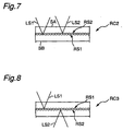
- a digital video disk recording medium with plural recording surfaces RS as described above is shown in Figs. 7 and 8.
- the DVD recording medium RC2 shown in Fig. 7 comprises two recording surfaces, i.e., first recording surface RS1 and semi-transparent second recording surface RS2, on the same side, i.e. side SA, of the disk. Data can be simultaneously recorded or reproduced from these two recording surfaces by using different laser beams LS1 and LS2 for the first recording surface RS1 and the second recording surface RS2. It is also possible to read/write both recording surfaces RS1 and RS2 using only one of the laser beams LS1 or LS2. Note that recording media thus comprised are called "single-side, dual-layer disks.”
- the DVD recording medium RC3 shown in Fig. 8 has the recording surfaces on opposite sides of the disk, i. e., has the first data recording surface RS1 on side SA and the second data recording surface RS2 on side SB. It will also be obvious that while only two recording surfaces are shown on one digital video disk in this example, more than two recording surfaces may also be formed on a double-sided digital video disk. As with the recording medium shown in Fig. 7, it is also possible to provide two separate laser beams LS1 and LS2 for recording surfaces RS1 and RS2, or to read/write both recording surfaces RS1 and RS2 using a single laser beam.
- double-sided, dual-layer disk This type of digital video disk is called a “double-sided, dual-layer disk.” It will also be obvious that a double-sided digital video disk can be comprised with two or more recording surfaces per side. This type of disk is called a “double-sided, multi-layer disk.”
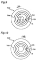
- FIG. 9 A plan view from the laser beam LS irradiation side of the recording surface RS of the DVD recording medium RC is shown in Fig. 9 and Fig. 10. Note that a continuous spiral data recording track TR is provided from the inside circumference to the outside circumference of the DVD. The data recording track TR is divided into plural sectors each having the same known storage capacity. Note that for simplicity only the data recording track TR is shown in Fig. 9 with more than three sectors per revolution.
- the data recording track TR is normally formed clockwise inside to outside (see arrow DrA) from the inside end point IA at the inside circumference of disk RCA to the outside end point OA at the outside circumference of the disk with the disk RCA rotating counterclockwise RdA.
- This type of disk RCA is called a clockwise disk, and the recording track formed thereon is called a clockwise track TRA.
- the recording track TRB may be formed clockwise from outside to inside circumference (see arrow DrB in Fig. 10) from the outside end point OB at the outside circumference of disk RCB to the inside end point IB at the inside circumference of the disk with the disk RCB rotating clockwise RdB. Because the recording track appears to wind counterclockwise when viewed from the inside circumference to the outside circumference on disks with the recording track formed in the direction of arrow DrB, these disks are referred to as counterclockwise disk RCB with counterclockwise track TRB to distinguish them from disk RCA in Fig. 9.
- track directions DrA and DrB are the track paths along which the laser beam travels when scanning the tracks for recording and playback.
- Direction of disk rotation RdA in which disk RCA turns is thus opposite the direction of track path DrA direction of disk rotation RdB in which disk RCB turns is thus opposite the direction of track path DrB.
- FIG. 7 An exploded view of the single-sided, dual-layer disk RC2 shown in Fig. 7 is shown as disk RC2o in Fig. 11. Note that the recording tracks formed on the two recording surfaces run in opposite directions. Specifically, a clockwise recording track TRA as shown in Fig. 9 is formed in clockwise direction DrA on the (lower) first data recording surface RS1, and a counterclockwise recording track TRB formed in counterclockwise direction DrB as shown in Fig. 10 is provided on the (upper) second data recording surface RS2. As a result, the outside end points OA and OB of the first and second (top and bottom) tracks are at the same radial position relative to the center axis of the disk RC2o.
- track paths DrA and DrB of tracks TR are also the data read/write directions to disk RC.
- the first and second (top and bottom) recording tracks thus wind opposite each other with this disk RC, i.e., the track paths DrA and DrB of the top and bottom recording layers are opposite track paths.
- Opposite track path type, single-sided, dual-layer disks RC2o rotate in direction RdA corresponding to the first recording surface RS1 with the laser beam LS traveling along track path DrA to trace the recording track on the first recording surface RS1.
- the laser beam LS can be refocused to end point OB on the second recording surface RS2 to continue tracing the recording track from the first to the second recording surface uninterrupted.
- the physical distance between the recording tracks TRA and TRB on the first and second recording surfaces RS1 and RS2 can thus be instantaneously eliminated by simply adjusting the focus of the laser beam LS.
- the tracks on recording surfaces RS1 and RS2 can be wound in the directions opposite those described above, i.e., the counterclockwise track TRB may be provided on the first recording surface RS1 and the clockwise track TRA on the second recording surface RS2.
- the direction of disk rotation is also changed to a clockwise rotation RdB, thereby enabling the two recording surfaces to be used as comprising a single continuous recording track as described above.
- a further example of this type of disk is therefore neither shown nor described below.
- the digital video disk it is therefore possible by thus constructing the digital video disk to record the multimedia bitstream MBS for a feature-length title to a single opposite track path type, single-sided, dual-layer disk RC2o. Note that this type of digital video disk medium is called a single-sided dual-layer disk with opposite track paths.
- FIG. 7 Another example of the single-sided, dual-layer DVD recording medium RC2 shown in Fig. 7 is shown as disk RC2p in Fig. 12.
- the recording tracks formed on both first and second recording surfaces RS1 and RS2 are clockwise tracks TRA as shown in Fig. 9.
- the single-sided, dual-layer disk RC2p rotates counterclockwise in the direction of arrow RdA, and the direction of laser beam LS travel is the same as the direction of the track spiral, i.e., the track paths of the top and bottom recording surfaces are mutually parallel (parallel track paths).
- the outside end points OA of both top and bottom tracks are again preferably positioned at the same radial position relative to the center axis of the disk RC2p as described above.
- the access point can be instantaneously shifted from outside end point OA of track TRA on the first recording surface RS1 to the outside end point OA of track TRA on the second recording surface RS2 by appropriately adjusting the focus of the laser beam LS at outside end point OA.
- the recording medium RC2p must be driven in the opposite direction (clockwise, opposite direction RdA).
- RdA opposite direction
- the laser beam LS is therefore moved from the outside end point OA of the track on the first recording surface RS1 to the inside end point IA of the track on the second recording surface RS2 to use these physically discrete recording tracks as one logically continuous recording track.
- This type of digital video disk recording medium is called a "single-sided, dual-layer disk with parallel track paths.”
- the single-sided, dual-layer disk RC2p with parallel track paths thus described is well-suited to storing on a single disk encyclopedia and similar multimedia bitstreams comprising multiple titles that are frequently and randomly accessed.
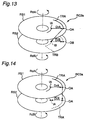
- FIG. 13 An exploded view of the dual-sided single-layer DVD recording medium RC3 comprising one recording surface layer RS1 and RS2 on each side as shown in Fig. 8 is shown as DVD recording medium RC3s in Fig. 13.
- Clockwise recording track TRA is provided on the one recording surface RS1
- a counterclockwise recording track TRB is provided on the other recording surface RS2.
- the outside end points OA and OB of the recording tracks on each recording surface are preferably positioned at the same radial position relative to the center axis of the DVD recording medium RC3s.
- This type of recording medium is therefore known as a double-sided dual layer disk with symmetrical track paths.
- This double-sided dual layer disk with symmetrical track paths RC3s rotates in direction RdA when reading/writing the first recording surface RS1.
- the track path on the second recording surface RS2 on the opposite side is opposite the direction DrB in which the track winds, i.e., direction DrA.
- Accessing both recording surfaces RS1 and RS2 using a single laser beam LS is therefore not realistic irrespective of whether access is continuous or non-continuous.
- a multimedia bitstream MBS is separately recorded to the recording surfaces on the first and second sides of the disk.
- FIG. 14 A different example of the double-sided single layer disk RC3 shown in Fig. 8 is shown in Fig. 14 as disk RC3a.
- this disk comprises clockwise recording tracks TRA as shown in Fig. 9 on both recording surfaces RS1 and RS2.
- the outside end points OA and OA of the recording tracks on each recording surface are preferably positioned at the same radial position relative to the center axis of the DVD recording medium RC3a.
- the tracks on these recording surfaces RS1 and RS2 are asymmetrical. This type of disk is therefore known as a double-sided dual layer disk with asymmetrical track paths.
- This double-sided dual layer disk with asymmetrical track paths RC3a rotates in direction RdA when reading/writing the first recording surface RS1.
- the track path on the second recording surface RS2 on the opposite side is opposite the direction DrA in which the track winds, i.e., direction DrB.
- both sides of the recording medium RC3a can be read/written without turning the disk over and without providing different laser beams for the two sides.
- the track paths for recording surfaces RS1 and RS2 are also the same with this double-sided dual layer disk with asymmetrical track paths RC3a.
- RC3a asymmetrical track paths
- this recording medium remains functionally identical even if counterclockwise recording track TRB is provided in place of clockwise recording track TRA on both recording surfaces RS1 and RS2.
- the true value of a DVD system whereby the storage capacity of the recording medium can be easily increased by using a multiple layer recording surface is realized in multimedia applications whereby plural video data units, plural audio data units, and plural graphics data units recorded to a single disk are reproduced through interactive operation by the user.
- the digital video disk recording medium is close to solving these problems.
- One interactive operation widely sought in multimedia applications today is for the user to be able to change the position from which a scene is viewed during reproduction of that scene. This capability is achieved by means of the multiple angle function.
- the available angles may include a position behind the backstop centered on the catcher, batter, and pitcher; one from behind the backstop centered on a fielder, the pitcher, and the catcher; and one from center field showing the view to the pitcher and catcher.
- the digital video disk system uses MPEG, the same basic standard format used with Video-Cds to record the video, audio, graphics, and other signal data. Because of the differences in storage capacity, transfer rates, and signal processing performance within the reproduction apparatus, DVD uses MPEG2, the compression method and data format of which differ slightly from the MPEG1 format used with Video-Cds.
- a fully functional and practical parental lock playback function and multi-angle scene playback function must enable the user to modify the system output in minor, subtle ways while still presenting substantially the same video and audio output. If these functions are achieved by preparing and recording separate titles satisfying each of the many possible parental lock and multi-angle scene playback requests, titles that are substantially identical and differ in only minor ways must be recorded to the recording medium. This results in identical data being repeatedly recorded to the larger part of the recording medium, and significantly reduces the utilization efficiency of the available storage capacity. More particularly, it is virtually impossible to record discrete titles satisfying every possible request even using the massive capacity of the digital video disk medium. While it may be concluded that this problem can be easily solved by increasing the capacity of the recording medium, this is an obviously undesirable solution when the effective use of available system resources is considered.
- multi-scene control the concept of which is described in another section below, in a DVD system, it is possible to dynamically construct titles for numerous variations of the same basic content using the smallest possible amount of data, and thereby effectively utilize the available system resources (recording medium). More specifically, titles that can be played back with numerous variations are constructed from basic (common) scene periods containing data common to each title, and multi-scene periods comprising groups of different scenes corresponding to the various requests. During reproduction, the user is able to freely and at any time select particular scenes from the multi-scene periods to dynamically construct a title conforming to the desired content, e.g., a title omitting certain scenes using the parental lock control function.
- Fig. 22 The data structure used in the authoring system of a digital video disk system according to the present invention is shown in Fig. 22.
- this digital video disk system divides the recording medium into three major recording areas, the lead-in area LI, the volume space VS, and the lead-out area LO.
- the lead-in area LI is provided at the inside circumference area of the optical disk. In the disks described with reference to Figs. 9 and 10, the lead-in area LI is positioned at the inside end points IA and IB of each track. Data for stabilizing the operation of the reproducing apparatus when reading starts is written to the lead-in area LI.
- the lead-out area LO is correspondingly located at the outside circumference of the optical disk, i.e., at outside end points OA and OB of each track in the disks described with reference to Figs. 9 and 10. Data identifying the end of the volume space VS is recorded in this lead-out area LO.
- the volume space VS is located between the lead-in area LI and lead-out area LO, and is recorded as a one-dimensional array of n+1 (where n is an integer greater than or equal to zero) 2048-byte logic sectors LS.
- the logic sectors LS are sequentially number #0, #1, #2, ... #n.
- the volume space VS is also divided into a volume and file structure management area VFS and a file data structure area FDS.
- the volume and file structure management area VFS comprises m+1 logic sectors LS#0 to LS#m (where m is an integer greater than or equal to zero and less than n.
- the file data structure FDS comprises n-m logic sectors LS #m+1 to LS #n.
- this file data structure area FDS corresponds to the multimedia bitstream MBS shown in Fig. 1 and described above.
- the volume file structure VFS is the file system for managing the data stored to the volume space VS as files, and is divided into logic sectors LS#0 - LS#m where m is the number of sectors required to store all data needed to manage the entire disk, and is a natural number less than n.
- Information for the files stored to the file data structure area FDS is written to the volume file structure VFS according to a known specification such as ISO-9660 or ISO-13346.
- the file data structure area FDS comprises n-m logic sectors LS#m - LS#n, each comprising a video manager VMG sized to an integer multiple of the logic sector (2048 x I, where I is a known integer), and k video title sets VTS #1 - VTS#k (where k is a natural number less than 100).
- the video manager VMG stores the title management information for the entire disk, and information for building a volume menu used to set and change reproduction control of the entire volume.
- Any video title set VTS #k is also called a "video file" representing a title comprising video, audio, and/or still image data.
- each video title set VTS comprises VTS information VTSI describing the management information for the entire disk, and the VTS title video objects VOB (VTSTT_VOBS), i.e., the system stream of the multimedia bitstream.
- VTSTT_VOBS VTS title video objects
- the VTS information VTSI is described first below, followed by the VTS title VOBS.
- the VTS information primarily includes the VTSI management table VTSI_MAT and VTSPGC information table VTS_PGCIT.
- the VTSI management table VTSI_MAT stores such information as the internal structure of the video title set VTS, the number of selectable audio streams contained in the video title set VTS, the number of sub-pictures, and the video title set VTS location (storage address).
- the VTSPGC information table VTS_PGCIT records i (where i is a natural number) program chain (PGC) data blocks VTS_PGCI #1 - VTS_PGCI #i for controlling the playback sequence.
- Each of the table entries VTS_PGCI #i is a data entry expressing the program chain, and comprises j (where j is a natural number) cell playback information blocks C_PBI #1 - C_PBI #j.
- Each cell playback information block C_PBI #j contains the playback sequence of the cell and playback control information.
- the program chain PGC is a conceptual structure describing the story of the title content, and therefore defines the structure of each title by describing the cell playback sequence. Note that these cells are described in detail below.
- the video title set information VTSI is stored to a buffer in the playback device when playback starts. If the user then presses a MENU button on a remote control device, for example, during playback, the playback device references the buffer to fetch the menu information and display the top menu #1. If the menus are hierarchical, the main menu stored as program chain information VTS_PGCI #1 may be displayed, for example, by pressing the MENU button, VTS_PGCI #2 - #9 may correspond to submenus accessed using the numeric keypad on the remote control, and VTS PGCI #10 and higher may correspond to additional submenus further down the hierarchy. Alternatively, VTS_PGCI #1 may be the top menu displayed by pressing the MENU button, while VTS_PGCI #2 and higher may be voice guidance reproduced by pressing the corresponding numeric key.
- the menus themselves are expressed by the plural program chains defined in this table.
- the menus may be freely constructed in various ways, and shall not be limited to hierarchical or non-hierarchical menus or menus containing voice guidance.
- the video title set information VTSI is stored to a buffer in the playback device when playback starts, the playback device references the cell playback sequence described by the program chain PGC, and reproduces the system stream.
- the "cells” referenced here may be all or part of the system stream, and are used as access points during playback. Cells can therefore be used, for example, as the "chapters" into which a title may be divided.
- each of the PGC information entries C_PBI #j contain both cell playback processing information and a cell information table.
- the cell playback processing information comprises the processing information needed to reproduce the cell, such as the presentation time and number of repetitions. More specifically, this information includes the cell block mode CBM, cell block type CBT, seamless playback flag SPF, interleaved allocation flag IAF, STC resetting flag STCDF, cell presentation time C_PBTM, seamless angle change flag SACF, first cell VOBU start address C_FVOBU_SA, and the last cell VOBU start address C_LVOBU_SA.
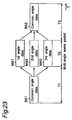
- seamless playback refers to the reproduction in a digital video disk system of multimedia data including video, audio, and sub-picture data without intermittent breaks in the data or information. Seamless playback is described in detail in another section below with reference to Fig. 23 and Fig. 24.
- the cell block mode CBM indicates whether plural cells constitute one functional block.
- the cell playback information of each cell in a functional block is arranged consecutively in the PGC information.
- the cell block mode CBM of the first cell playback information in this sequence contains the value of the first cell in the block
- the cell block mode CBM of the last cell playback information in this sequence contains the value of the last cell in the block.
- the cell block mode CBM of each cell arrayed between these first and last cells contains a value indicating that the cell is a cell between these first and last cells in that block.
- the cell block type CBT identifies the type of the block indicated by the cell block mode CBM. For example, when a multiple angle function is enabled, the cell information corresponding to each of the reproducible angles is programmed as one of the functional blocks mentioned above, and the type of these functional blocks is defined by a value identifying "angle" in the cell block type CBT for each cell in that block.
- the seamless playback flag SPF simply indicates whether the corresponding cell is to be linked and played back seamlessly with the cell or cell block reproduced immediately therebefore. To seamlessly reproduce a given cell with the preceding cell or cell block, the seamless playback flag SPF is set to 1 in the cell playback information for that cell; otherwise SPF is set to 0.
- the interleaved allocation flag IAF stores a value identifying whether the cell exists in a contiguous or interleaved block. If the cell is part of an interleaved block, the flag IAF is set to 1; otherwise it is set to 0.
- the STC resetting flag STCDF identifies whether the system time clock STC used for synchronization must be reset when the cell is played back; when resetting the system time clock STC is necessary, the STC resetting flag STCDF is set to 1.
- the seamless angle change flag SACF stores a value indicating whether a cell in a multi-angle period should be connected seamlessly at an angle change. If the angle change is seamless, the seamless angle change flag SACF is set to 1; otherwise it is set to 0.
- the cell presentation time C_PBTM expresses the cell presentation time with video frame precision.
- the first cell VOBU start address C_FVOBU_SA is the VOBU start address of the first cell in a block, and is also expressed as the distance from the logic sector of the first cell in the VTS title VOBS (VTSTT_VOBS) as measured by the number of sectors.
- the last cell VOBU start address C_LVOBU_SA is the VOBU start address of the last cell in the block.
- the value of this address is expressed as the distance from the logic sector of the first cell in the VTS title VOBS (VTSTT_VOBS) as measured by the number of sectors.
- VTSTT_VOBS The VTS title VOBS (VTSTT_VOBS), i.e., the multimedia system stream data, is described next.
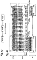
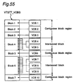
- the system stream data VTSTT_VOBS comprises i (where i is a natural number) system streams SS, each of which is referred to as a "video object" (VOB).
- Each video object VOB #1 - VOB #i comprises at least one video data block interleaved with up to a maximum eight audio data blocks and up to a maximum 32 sub-picture data blocks.
- Each video object VOB comprises q (where q is a natural number) cells C#1 - C#q.
- Each cell C comprises r (where r is a natural number) video object units VOBU #1 - VOBU #r.
- Each video object unit VOBU comprises plural groups_of_pictures GOP, and the audio and sub-pictures corresponding to the playback of said plural groups_of_pictures GOP. Note that the group_of_pictures GOP corresponds to the video encoding refresh cycle.
- Each video object unit VOBU also starts with an NV pack, i.e., the control data for that VOBU.
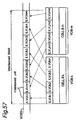
- the internal structure of the video zone VZ (see Fig. 22), i.e., the system stream St35 encoded by the authoring encoder EC described with reference to Fig. 25, is described with reference to Fig. 17.
- the encoded video stream St15 shown in Fig. 17 is the compressed one-dimensional video data stream encoded by the video encoder 300.
- the encoded audio stream St19 is likewise the compressed one-dimensional audio data stream multiplexing the right and left stereo audio channels encoded by the audio encoder 700.
- the audio signal shall not be limited to a stereo signal, and may also be a multichannel surround-sound signal.
- the system stream (title editing unit VOB) St35 is a one dimensional array of packs with a byte size corresponding to the logic sectors LS #n having a 2048-byte capacity as described using Fig. 21.
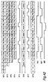
- a stream control pack is placed at the beginning of the title editing unit (VOB) St35, i.e., at the beginning of the video object unit VOBU. This stream control pack is called the "navigation pack NV", and records the data arrangement in the system stream and other control information.
- the encoded video stream St15 and the encoded audio stream St19 are packetized in byte units corresponding to the system stream packs. These packets are shown in Fig. 17 as packets V1, V2, V3, V4... and A1, A2, A3.... As shown in Fig. 17, these packets are interleaved in the appropriate sequence as system stream St35, thus forming a packet stream, with consideration given to the decoder buffer size and the time required by the decoder to expand the video and audio data packets. In the example shown in Fig. 17, the packet stream is interleaved in the sequence V1, V2, A1, V3, V4, A2....
- Fig. 17 interleaves one video data unit with one audio data unit.
- Significantly increased recording/playback capacity, high speed recording/playback, and performance improvements in the signal processing LSI enable the DVD system to record plural audio data and plural sub-picture data (graphics data) to one video data unit in a single interleaved MPEG system stream, and thereby enable the user to select the specific audio data and sub-picture data to be reproduced during playback.
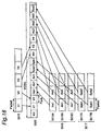
- the structure of the system stream used in this type of DVD system is shown in Fig. 18 and described below.
- the packetized encoded video stream St15 is shown in Fig. 18 as V1, V2, V3, V4, ... In this example, however, there is not just one encoded audio stream St19, but three encoded audio streams St19A, St19B, and St19C input as the source data. There are also two encoded sub-picture streams St17A and St17B input as the source data sub-picture streams. These six compressed data streams, St15, St19A, St19B, St19C, St17A and St17B, are interleaved to a single system stream St35.
- the video data is encoded according to the MPEG specification with the group_of_pictures GOP being the unit of compression.
- each group_of_pictures GOP contains 15 frames in the case of an NTSC signal, but the specific number of frames compressed to one GOP is variable.
- the stream management pack which describes the management data containing, for example, the relationship between interleaved data, is also interleaved at the GOP unit interval. Because the group_of_pictures GOP unit is based on the video data, changing the number of video frames per GOP unit changes the interval of the stream management packs. This interval is expressed in terms of the presentation time on the digital video disk within a range from 0.4 sec. to 1.0 sec. referenced to the GOP unit. If the presentation time of contiguous plural GOP units is less than 1 sec., the management data packs for the video data of the plural GOP units is interleaved to a single stream.
- These management data packs are referred to as navigation packs NV in the digital video disk system.
- the data from one navigation pack NV to the packet immediately preceding the next navigation pack NV forms one video object unit VOBU.
- one contiguous playback unit that can be defined as one scene is called a video object VOB, and each video object VOB contains plural video object units VOBU.
- Data sets of plural video objects VOB form a VOB set (VOBS). Note that these data units were first used in the digital video disk.
- each group_of_pictures GOP is normally a unit containing approximately 0. 5 sec. of video data, which is equivalent to the presentation time required for 12 - 15 frames, and one navigation pack NV is generally interleaved with the number of data packets required for this presentation time.
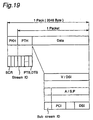
- the stream management information contained in the interleaved video, audio, and sub-picture data packets constituting the system stream is described below with reference to Fig. 19
- the data contained in the system stream is recorded in a format packed or packetized according to the MPEG2 standard.
- the packet structure is essentially the same for video, audio, and sub-picture data.
- One pack in the digital video disk system has a 2048 byte capacity as described above, and contains a pack header PKH and one packet PES; each packet PES contains a packet header PTH and data block.
- the pack header PKH records the time at which that pack is to be sent from stream buffer 2400 to system decoder 2500 (see Fig. 26), i.e., the system clock reference SCR defining the reference time for synchronized audio-visual data playback.
- the system clock reference SCR is the reference clock for the entire decoder operation. With such disk media as the digital video disk, however, time management specific to individual disk players can be used, and a reference clock for the decoder system is therefore separately provided.
- the packet header PTH similarly contains a presentation time stamp PTS and a decoding time stamp DTS, both of which are placed in the packet before the access unit (the decoding unit).
- the presentation time stamp PTS defines the time at which the video data or audio data contained in the packet should be output as the playback output after being decoded
- the decoding time stamp DTS defines the time at which the video stream should be decoded. Note that the presentation time stamp PTS effectively defines the display start timing of the access unit, and the decoding time stamp DTS effectively defines the decoding start timing of the access unit. If the PTS and DTS are the same time, the DTS is omitted;
- the packet header PTH also contains an 8-bit field called the stream ID identifying the packet type, i.e., whether the packet is a video packet containing a video data stream, a private packet, or an MPEG audio packet.
- Private packets under the MPEG2 standard are data packets of which the content can be freely defined.
- Private packet 1 in this embodiment of the invention is used to carry audio data other than the MPEG audio data, and sub-picture data;
- private packet 2 carries the PCI packet and DSI packet.
- Private packets 1 and 2 each comprise a packet header, private data area, and data area.
- the private data area contains an 8-bit sub-stream ID indicating whether the recorded data is audio data or sub-picture data.
- the audio data defined by private packet 2 may be defined as any of eight types #0 - #7 of linear PCM or AC-3 encoded data.
- Sub-picture data may be defined as one of up to 32 types #0 - #31.
- the data area is the field to which data compressed according to the MPEG2 specification is written if the stored data is video data; linear PCM, AC-3, or MPEG encoded data is written if audio data is stored; or graphics data compressed by runlength coding is written if sub-picture data is stored.
- MPEG2-compressed video data may be compressed by constant bit rate (CBR) or variable bit rate (VBR) coding.
- CBR constant bit rate
- VBR variable bit rate
- constant bit rate coding the video stream is input continuously to the video buffer at a constant rate. This contrasts with variable bit rate coding in which the video stream is input intermittently to the video buffer, thereby making it possible to suppress the generation of unnecessary code.
- constant bit rate and variable bit rate coding can be used in the digital video disk system.
- Each navigation pack NV starts with a pack header PKH, and contains a PCI packet and DSI packet.
- the pack header PKH records the time at which that pack is to be sent from stream buffer 2400 to system decoder 2500 (see Fig. 26 ), i.e., the system clock reference SCR defining the reference time for synchronized audio-visual data playback.
- PCI_GI PCI General Information
- NMSL_AGLI Angle Information for Non-seamless playback
- PCI General Information declares the display time of the first video frame (the Start PTM of VOBU (VOBU_S_PTM)), and the display time of the last video frame (End PTM of VOBU (VOBU_E_PTM)), in the corresponding video object unit VOBU with system clock precision (90 Khz).
- the Angle Information for Non-seamless playback states the read start address of the corresponding video object unit VOBU when the angle is changed expressed as the number of sectors from the beginning of the video object VOB. Because there are nine or fewer angles in this example, there are nine angle address declaration cells: Destination Address of Angle Cell #1 for Non-seamless playback (NMSL_AGL_C1_DSTA) to Destination Address of Angle Cell #9 for Non-seamless playback (NMSL_AGL_C9_DSTA).
- Each DSI packet contains DSI General Information (DSI_GI), Seamless Playback Information (SML_PBI), and Angle Information for Seamless playback (SML_AGLI).
- DSI_GI DSI General Information
- SML_PBI Seamless Playback Information
- SML_AGLI Angle Information for Seamless playback
- the DSI General Information declares the address of the last pack in the video object unit VOBU, i. e., the End Address for VOB (VOBU_EA), expressed as the number of sectors from the beginning of the video object unit VOBU.
- the Seamless Playback Information (SML_PBI) is declared to seamlessly reproduce the stream interleaved with the interleaved unit ILVU as the smallest data unit, and contains an Interleaved Unit Flag (ILVU flag) identifying whether the corresponding video object unit VOBU is an interleaved block.
- ILVU flag indicates whether the video object unit VOBU is in an interleaved block, and is set to 1 when it is. Otherwise the ILVU flag is set to 0.
- a Unit END flag is declared to indicate whether the video object unit VOBU is the last VOBU in the interleaved unit ILVU. Because the interleaved unit ILVU is the data unit for continuous reading, the Unit END flag is set to 1 if the VOBU currently being read is the last VOBU in the interleaved unit ILVU. Otherwise the Unit END flag is set to 0.
- Interleaved Unit End Address (ILVU_EA) identifying the address of the last pack in the ILVU to which the VOBU belongs, and the starting address of the next interleaved unit ILVU, Next Interleaved Unit Start Address (NT_ILVU_SA), are also declared when a video object unit VOBU is in an interleaved block. Both the Interleaved Unit End Address (ILVU_EA) and Next Interleaved Unit Start Address (NT_ILVU_SA) are expressed as the number of sectors from the navigation pack NV of that VOBU.
- the audio components of the two system streams are not contiguous, particularly immediately before and after the seam, it is necessary to pause the audio output to synchronize the audio and video components of the system stream following the seam.
- non-contiguous audio may result from different audio signals being recording with the corresponding video blocks.
- the video frame cycle is approximately 33. 33 msec while the AC-3 audio frame cycle is 32 msec.
- audio reproduction stopping times 1 and 2 i.e., Audio Stop PTM 1 in VOB (VOB_A_STP_PTM1), and Audio Stop PTM2 in VOB (VOB_A_STP_PTM2), indicating the time at which the audio is to be paused; and audio reproduction stopping periods 1 and 2, i.e., Audio Gap Length 1 in VOB (VOB_A_GAP_LEN1) and Audio Gap Length 2 in VOB (VOB_A_GAP_LEN2), indicating for how long the audio is to be paused, are also declared in the DSI packet. Note that these times are specified at the system clock precision (90 Khz).
- the Angle Information for Seamless playback (SML_AGLI) declares the read start address when the angle is changed. Note that this field is valid when seamless, multi-angle control is enabled. This address is also expressed as the number of sectors from the navigation pack NV of that VOBU. Because there are nine or fewer angles, there are nine angle address declaration cells: Destination Address of Angle Cell #1 for Seamless playback (SML_AGL_C1_DSTA) to Destination Address of Angle Cell #9 for Seamless playback (SML_AGL_C9_DSTA).
- each title is edited in video object (VOB) units.
- Interleaved video objects are referenced as “VOBS”; and the encoded range of the source data is the encoding unit.
- a preferred embodiment of a digital video disk system authoring encoder ECD in which the multimedia bitstream authoring system according to the present invention is applied to a digital video disk system is described below and shown in Fig. 25.
- the authoring encoder ECD applied to the digital video disk system referred to below as a DVD encoder
- the replacement in the DVD encoder ECD of the video zone formatter 1300 of the authoring encoder EC above with a VOB buffer 1000 and formatter 1100 is recorded to a digital video disk medium M. The operation of this DVD encoder ECD is therefore described below in comparison with the authoring encoder EC described above.
- the encoding system controller 200 generates control signals St9, St11, St13, St21, St23, St25, St33, and St39 based on the scenario data St7 describing the user-defined editing instructions input from the scenario editor 100, and controls the video encoder 300, sub-picture encoder 500, and audio encoder 700 in the DVD encoder ECD.
- the user-defined editing instructions in the DVD encoder ECD are a superset of the editing instructions of the authoring encoder EC described above.
- the user-defined editing instructions (scenario data St7) in the DVD encoder ECD similarly describe what source data is selected from all or a subset of the source data containing plural titles within a defined time period, and how the selected source data is reassembled to reproduce the scenario (sequence) intended by the user.
- the scenario data St7 of the DVD encoder ECD further contains such information as: the number of streams contained in the editing units, which are obtained by splitting a multi-title source stream into blocks at a constant time interval; the number of audio and sub-picture data cells contained in each stream, and the sub-picture display time and period; whether the title is a multi-rated title enabling parental lock control; whether the user content is selected from plural streams including, for example, multiple viewing angles; and the method of connecting scenes when the angle is switched among the multiple viewing angles.
- the scenario data St7 of the DVD encoder ECD also contains control information on a video object VOB unit basis. This information is required to encode the media source stream, and specifically includes such information as whether there are multiple angles or parental control features. When multiple angle viewing is enabled, the scenario data St7 also contains the encoding bit rate of each stream considering data interleaving and the disk capacity, the start and end times of each control, and whether a seamless connection should be made between the preceding and following streams.
- the encoding system controller 200 extracts this information from the scenario data St7, and generates the encoding information table and encoding parameters required for encoding control.
- the encoding information table and encoding parameters are described with reference to Figs. 27, 28, and 29 below.
- the stream encoding data St33 contains the system stream encoding parameters and system encoding start and end timing values required by the DVD system to generate the VOBs.
- These system stream encoding parameters include the conditions for connecting one video object VOB with those before and after, the number of audio streams, the audio encoding information and audio Ids, the number of sub-pictures and the sub-picture Ids, the video playback starting time information VPTS, and the audio playback starting time information APTS.
- the title sequence control signal St39 supplies the multimedia bitstream MBS formatting start and end timing information and formatting parameters declaring the reproduction control information and interleave information.
- the video encoder 300 Based on the video encoding parameter and encoding start/end timing signal St9, the video encoder 300 encodes a specific part of the video stream St1 to generate an elementary stream conforming to the MPEG2 Video standard defined in ISO-13818. This elementary stream is output to the video stream buffer 400 as encoded video stream St15.
- the video encoder 300 generates an elementary stream conforming to the MPEG2 Video standard defined in ISO-13818
- specific encoding parameters are input via the video encoding parameter signal St9, including the encoding start and end timing, bit rate, the encoding conditions for the encoding start and end, the material type, including whether the material is an NTSC or PAL video signal or telecine converted material, and whether the encoding mode is set for either open GOP or closed GOP encoding.
- the MPEG2 coding method is basically an interframe coding method using the correlation between frames for maximum signal compression, i.e., the frame being coded (the target frame) is coded by referencing frames before and/or after the target frame.
- intra-coded frames i. e. , frames that are coded based solely on the content of the target frame, are also inserted to avoid error propagation and enable accessibility from mid-stream (random access).
- the coding unit containing at least one intra-coded frame (“intra-frame”) is called a group_of_pictures GOP.
- a group_of_pictures GOP in which coding is closed completely within that GOP is known as a "closed GOP.
- a group_of_pictures GOP containing a frame coded with reference to a frame in a preceding or following (ISO-13818 DOES NOT LIMIT P- and B-picture CODING to referencing PAST frames) group_of_pictures GOP is an "open GOP.” It is therefore possible to playback a closed GOP using only that GOP. Reproducing an open GOP, however, also requires the presence of the referenced GOP, generally the GOP preceding the open GOP.
- the GOP is often used as the access unit.
- the GOP may be used as the playback start point for reproducing a title from the middle, as a transition point in a movie, or for fast-forward play and other special reproduction modes. High speed reproduction can be achieved in such cases by reproducing only the intra-frame coded frames in a GOP or by reproducing only frames in GOP units.
- the sub-picture encoder 500 encodes a specific part of the sub-picture stream St3 to generate a variable length coded bitstream of bitmapped data. This variable length coded bitstream data is output as the encoded sub-picture stream St17 to the sub-picture stream buffer 600.
- the audio encoder 700 Based on the audio encoding parameter signal St13, the audio encoder 700 encodes a specific part of the audio stream St5 to generate the encoded audio data.
- This encoded audio data may be data based on the MPEG1 audio standard defined in ISO-11172 and the MPEG2 audio standard defined in ISO-13818, AC-3 audio data, or PCM (LPCM) data. Note that the methods and means of encoding audio data according to these standards are known and commonly available.
- the video stream buffer 400 is connected to the video encoder 300 and to the encoding system controller 200.
- the video stream buffer 400 stores the encoded video stream St15 input from the video encoder 300, and outputs the stored encoded video stream St15 as the time-delayed encoded video stream St27 based on the timing signal St21 supplied from the encoding system controller 200.
- the sub-picture stream buffer 600 is similarly connected to the sub-picture encoder 500 and to the encoding system controller 200.
- the sub-picture stream buffer 600 stores the encoded sub-picture stream St17 input from the sub-picture encoder 500, and then outputs the stored encoded sub-picture stream St17 as time-delayed encoded sub-picture stream St29 based on the timing signal St23 supplied from the encoding system controller 200.
- the audio stream buffer 800 is similarly connected to the audio encoder 700 and to the encoding system controller 200.
- the audio stream buffer 800 stores the encoded audio stream St19 input from the audio encoder 700, and then outputs the encoded audio stream St19 as the time-delayed encoded audio stream St31 based on the timing signal St25 supplied from the encoding system controller 200.
- the system encoder 900 is connected to the video stream buffer 400, sub-picture stream buffer 600, audio stream buffer 800, and the encoding system controller 200, and is respectively supplied thereby with the time-delayed encoded video stream St27, time-delayed encoded sub-picture stream St29, time-delayed encoded audio stream St31, and the system stream encoding parameter data St33.
- the system encoder 900 is a multiplexer that multiplexes the time-delayed streams St27, St29, and St31 based on the stream encoding data St33 (timing signal) to generate title editing units (VOBs) St35.
- the VOB buffer 1000 temporarily stores the video objects VOBs produced by the system encoder 900.
- the formatter 1100 reads the delayed video objects VOB from the VOB buffer 1000 based on the title sequence control signal St39 to generate one video zone VZ, and adds the volume file structure VFS to generate the edited multimedia stream data St43.
- the multimedia bitstream MBS St43 edited according to the user-defined scenario is then sent to the recorder 1200.
- the recorder 1200 processes the edited multimedia stream data St43 to the data stream St45 format of the recording medium M, and thus records the formatted data stream St45 to the recording medium M.
- a preferred embodiment of a digital video disk system authoring decoder DCD in which the multimedia bitstream authoring system of the present invention is applied to a digital video disk system is described below and shown in Fig. 26.
- the authoring decoder DCD applied to the digital video disk system referred to below as a DVD decoder DCD, decodes the multimedia bitstream MBS edited using the DVD encoder ECD of the present invention, and recreates the content of each title according to the user-defined scenario. It will also be obvious that the multimedia bitstream St45 encoded by this DVD encoder ECD is recorded to a digital video disk medium M.
- the basic configuration of the DVD decoder DCD according to this embodiment is the same as that of the authoring decoder DC shown in Fig. 3. The differences are that a different video decoder 3801 (shown as 3800 in Fig. 26) is used in place of the video decoder 3800, and a reordering buffer 3300 and selector 3400 are disposed between the video decoder 3801 and synthesizer 3500.
- a different video decoder 3801 shown as 3800 in Fig. 26
- a reordering buffer 3300 and selector 3400 are disposed between the video decoder 3801 and synthesizer 3500.
- selector 3400 is connected to the synchronizer 2900, and is controlled by a switching signal St103.
- the DVD decoder DCD comprises a multimedia bitstream producer 2000, scenario selector 2100, decoding system controller 2300, stream buffer 2400, system decoder 2500, video buffer 2600, sub-picture buffer 2700, audio buffer 2800, synchronizer 2900, video decoder 3801, reordering buffer 3300, sub-picture decoder 3100, audio decoder 3200, selector 3400, synthesizer 3500, video data output terminal 3600, and audio data output terminal 3700.
- the bitstream producer 2000 comprises a recording media drive unit 2004 for driving the recording medium M; a reading head 2006 for reading the information recorded to the recording medium M and producing the binary read signal St57; a signal processor 2008 for variously processing the read signal St57 to generate the reproduced bitstream St61; and a reproduction controller 2002.
- the reproduction controller 2002 is connected to the decoding system controller 2300 from which the multimedia bitstream reproduction control signal St53 is supplied, and in turn generates the reproduction control signals St55 and St59 respectively controlling the recording media drive unit (motor) 2004 and signal processor 2008.
- the authoring decoder DC comprises a scenario selector 2100 for selecting and reproducing the corresponding scenes (titles).
- the scenario selector 2100 then outputs the selected titles as scenario data to the DVD decoder DCD.
- the scenario selector 2100 preferably comprises a keyboard, CPU, and monitor. Using the keyboard, the user then inputs the desired scenario based on the content of the scenario input by the DVD encoder ECD. Based on the keyboard input, the CPU generates the scenario selection data St51 specifying the selected scenario.
- the scenario selector 2100 is connected to the decoding system controller 2300 by an infrared communications device, for example, and inputs the generated scenario selection data St51 to the decoding system controller 2300.
- the stream buffer 2400 has a specific buffer capacity used to temporarily store the reproduced bitstream St61 input from the bitstream producer 2000, extract the volume file structure VFS, the initial synchronization data SCR (system clock reference) in each pack, and the VOBU control information (DSI) in the navigation pack NV, to generate the bitstream control data St63.
- the stream buffer 2400 is also connected to the decoding system controller 2300, to which it supplies the generated bitstream control data St63.
- the decoding system controller 2300 Based on the scenario selection data St51 supplied by the scenario selector 2100, the decoding system controller 2300 then generates the bitstream reproduction control signal St53 controlling the operation of the bitstream producer 2000.
- the decoding system controller 2300 also extracts the user-defined playback instruction data from the bitstream reproduction control signal St53, and generates the decoding information table required for decoding control. This decoding information table is described further below with reference to Figs. 47 and 48.
- the decoding system controller 2300 also extracts the title information recorded to the optical disk M from the file data structure area FDS of the bitstream control data St63 to generate the title information signal St200. Note that the extracted title information includes the video manager VMG, VTS information VTSI, the PGC information entries C_PBI #j, and the cell presentation time C_PBTM.
- bitstream control data St63 is generated in pack units as shown in Fig. 19, and is supplied from the stream buffer 2400 to the decoding system controller 2300, to which the stream buffer 2400 is connected.
- the synchronizer 2900 is connected to the decoding system controller 2300 from which it receives the system clock reference SCR contained in the synchronization control data St81 to set the internal system clock STC and supply the reset system clock St79 to the decoding system controller 2300.
- the decoding system controller 2300 Based on this system clock St79, the decoding system controller 2300 also generates the stream read signal St65 at a specific interval and outputs the read signal St65 to the stream buffer 2400. Note that the read unit in this case is the pack.
- the decoding system controller 2300 compares the system clock reference SCR contained in the stream control data extracted from the stream buffer 2400 with the system clock St79 supplied from the synchronizer 2900, and generates the read request signal St65 when the system clock St79 is greater than the system clock reference SCR of the bitstream control data St63. Pack transfers are controlled by executing this control process on a pack unit.
- the decoding system controller 2300 Based on the scenario selection data St51, the decoding system controller 2300 generates the decoding signal St69 defining the stream Ids for the video, sub-picture, and audio bitstreams corresponding to the selected scenario, and outputs to the system decoder 2500.
- a title contains plural audio tracks, e.g. audio tracks in Japanese, English, French, and/or other languages, and plural sub-picture tracks for subtitles in Japanese, English, French, and/or other languages, for example, a discrete ID is assigned to each of the language tracks.
- a stream ID is assigned to the video data and MPEG audio data
- a substream ID is assigned to the sub-picture data, AC-3 audio data, linear PCM data, and navigation pack NV information. While the user need never be aware of these ID numbers, the user can select the language of the audio and/or subtitles using the scenario selector 2100.
- the ID corresponding to the English audio track is sent to the decoding system controller 2300 as scenario selection data St51.
- the decoding system controller 2300 then adds this ID to the decoding signal St69 output to the system decoder 2500.
- the system decoder 2500 Based on the instructions contained in the decoding signal St69, the system decoder 2500 respectively outputs the video, sub-picture, and audio bitstreams input from the stream buffer 2400 to the video buffer 2600, sub-picture buffer 2700, and audio buffer 2800 as the encoded video stream St71, encoded sub-picture stream St73, and encoded audio stream St75.
- the system decoder 2500 outputs the corresponding packs to the respective buffers (i.e., the video buffer 2600, sub-picture buffer 2700, and audio buffer 2800).
- the system decoder 2500 detects the presentation time stamp PTS and decoding time stamp DTS of the smallest control unit in each bitstream St67 to generate the time information signal St77.
- This time information signal St77 is supplied to the synchronizer 2900 through the decoding system controller 2300 as the synchronization control data St81.
- the synchronizer 2900 determines the decoding start timing whereby each of the bitstreams will be arranged in the correct sequence after decoding, and then generates and inputs the video stream decoding start signal St89 to the video decoder 3801 based on this decoding timing.
- the synchronizer 2900 also generates and supplies the sub-picture decoding start signal St91 and audio stream decoding start signal St93 to the sub-picture decoder 3100 and audio decoder 3200, respectively.
- the video decoder 3801 generates the video output request signal St84 based on the video stream decoding start signal St89, and outputs to the video buffer 2600.
- the video buffer 2600 outputs the video stream St83 to the video decoder 3801.
- the video decoder 3801 thus detects the presentation time information contained in the video stream St83, and disables the video output request signal St84 when the length of the received video stream St83 is equivalent to the specified presentation time.
- a video stream equal in length to the specified presentation time is thus decoded by the video decoder 3801, which outputs the reproduced video signal St95 to the reordering buffer 3300 and selector 3400.
- the coded order and display order do not necessarily match on a frame unit basis.
- the video cannot, therefore, be displayed in the decoded order.
- the decoded frames are therefore temporarily stored to the reordering buffer 3300.
- the synchronizer 2900 therefore controls the switching signal St103 so that the reproduced video signal St95 output from the video decoder 3800 and the reordering buffer output St97 are appropriately selected and output in the display order to the synthesizer 3500.
- the sub-picture decoder 3100 similarly generates the sub-picture output request signal St86 based on the sub-picture decoding start signal St91, and outputs to the sub-picture buffer 2700.
- the sub-picture buffer 2700 outputs the sub-picture stream St85 to the sub-picture decoder 3100.
- the sub-picture decoder 3100 decodes a length of the sub-picture stream St85 corresponding to the specified presentation time to reproduce and supply to the synthesizer 3500 the sub-picture signal St99.
- the synthesizer 3500 superimposes the selector 3400 output with the sub-picture signal St99 to generate and output the video signal St105 to the video data output terminal 3600.
- the audio decoder 3200 generates and supplies to the audio buffer 2800 the audio output request signal St88 based on the audio stream decoding start signal St93.
- the audio buffer 2800 thus outputs the audio stream St87 to the audio decoder 3200.
- the audio decoder 3200 decodes a length of the audio stream St87 corresponding to the specified presentation time based on the presentation time information contained in the audio stream St87, and outputs the decoded audio stream St101 to the audio data output terminal 3700.
- the DVD decoder DCD is able to reproduce the title content desired by the user in the desired sequence by reproducing the multimedia bitstream MBS corresponding to the selected scenario.
- the decoding system controller 2300 may supply the title information signal St200 to the scenario selector 2100 by means of the infrared communications device mentioned above or another means.
- Interactive scenario selection controlled by the user can also be made possible by the scenario selector 2100 extracting the title information recorded to the optical disk M from the file data structure area FDS of the bitstream control data St63 contained in the title information signal St200, and displaying this title information on a display for user selection.
- stream buffer 2400, video buffer 2600, sub-picture buffer 2700, audio buffer 2800, and reordering buffer 3300 are expressed above and in the figures as separate entities because they are functionally different. It will be obvious, however, that a single buffer memory can be controlled to provide the same discrete functionality by time-share controlled use of a buffer memory with an operating speed plural times faster than the read and write rates of these separate buffers.
- Fig. 21 The concept of multiple angle scene control according to the present invention is described below with reference to Fig. 21.
- titles that can be played back with numerous variations are constructed from basic scene periods containing data common to each title, and multi-scene periods comprising groups of different scenes corresponding to the various scenario requests.
- scenes 1, 5, and 8 are the common scenes of the basic scene periods.
- the multi-angle scenes (angles 1, 2, and 3) between scenes 1 and 5, and the parental locked scenes (scenes 6 and 7) between scenes 5 and 8, are the multi-scene periods.
- Scenes taken from different angles can be dynamically selected and reproduced during playback in the multi-angle scene period.
- angles 1, 2, and 3 in this example, can be dynamically selected and reproduced during playback in the multi-angle scene period.
- the parental locked scene period however, only one of the available scenes, scenes 6 and 7, having different content can be selected, and must be selected statically before playback begins.
- VTS_PGCI the contents of the program chain information VTS_PGCI is described.
- Fig. 30 the case that a scenario requested by the user is shown with respect to a VTSI data construction.
- the scenario 1 and scenario 2 shown in Fig. 21 are described as program chain information VTS_PGC#1 and VTS_PGC#2.
- VTS_PGC#1 describing the scenario 1 consists of cell playback information C_PBI#1 corresponding to scene 1, C_PBI#2, C_PBI#3, and C_PBI#4 within a multi-angle cell block, C_PBI#5 corresponding to scene 5, C_PBI#6 corresponding to scene 6, and C_PBI#7 corresponding to scene 8.
- VTS_PGCI#2 describing the scenario 2 consists of cell playback information C_PBI#1 corresponding to scene 1, C_PBI#2, C_PBI#3, and C_PBI#4 within a multi-angle cell block corresponding to a multi-angle scene, C_PBI#5 corresponding to scene 5, C_PBI#6 corresponding to scene 7, and C_PBI#7 corresponding to scene 8.
- C_PBI#1 cell playback information
- C_PBI#2 C_PBI#3, and C_PBI#4 within a multi-angle cell block corresponding to a multi-angle scene
- C_PBI#5 corresponding to scene 5 C_PBI#6 corresponding to scene 7
- C_PBI#7 corresponding to scene 8.
- FIG. 31 the case that a scenario requested by the user shown in Fig. 21 is shown with respect to a VOB data construction VTSTT_VOBS.
- VTSTT_VOBS VOB data construction
- the two scenarios 1 and 2 use the same VOB data in common.
- VOB#1 corresponding to scene 1 VOB#5 corresponding to scene 5
- VOB#8 corresponding to scene 8 are arranged in non-interleaved block which is the contiguous block.
- one angle scene data is constructed by a single VOB.
- angle 1 is constructed by VOB#2
- angle 2 is constructed by VOB#3
- angle 3 is constructed by VOB#4.
- constructed multi-angle data is formed as the interleaved block for the sake of switching between each angle and seamless reproduction of each angle data.
- Scenes 6 and 7 peculiar to scenarios 1 and 2, respectively, are formed as the interleaved block for the sake of seamless reproduction between common scenes before and behind thereof as well as seamless reproduction between each scene.
- the user's requesting scenario shown in Fig. 21 can be realized by utilizing the video title playback control information shown in Fig. 30 and the title playback VOB data structure shown in Fig. 31.
- seamless playback refers to the reproduction in a digital video disk system of multimedia data including video, audio, and sub-picture data without intermittent breaks in the data or information between basic scene periods, between basic scene periods and multi-scene periods, and between multi-scene periods.
- Hardware factors contributing to intermittent playback of this data and title content include decoder underflow, i.e., an imbalance between the source data input speed and the decoding speed of the input source data.
- the playback data is data that must be continuously reproduced for a constant time unit in order for the user to understand the content or information, e.g., audio data
- data continuity is lost when the required continuous presentation time cannot be assured.
- Reproduction of such information whereby the required continuity is assured is referred to as "contiguous information reproduction,” or “seamless information reproduction.”
- Reproduction of this information when the required continuity cannot be assured is referred to as “non-continuous information reproduction,” or “non-seamless information reproduction.” It is obvious that continuous information reproduction and non-continuous information reproduction are, respectively, seamless and non-seamless reproduction.
- seamless reproduction can be further categorized as seamless data reproduction and seamless information reproduction.
- Seamless data reproduction is defined as preventing physical blanks or interruptions in the data playback (intermittent reproduction) as a result of a buffer underflow state, for example.
- Seamless information reproduction is defined as preventing apparent interruptions in the information when perceived by the user (intermittent presentation) when recognizing information from the playback data where there are no actual physical breaks in the data reproduction.
- the DVD data system streams described above are recorded using an appropriate authoring encoder EC as a movie or other multimedia title on a DVD recording medium. Note that the following description refers to a movie as the multimedia title being processed, but it will be obvious that the invention shall not be so limited.
- the titles recorded to a single optical disk contain basic scene periods of scenes common to all scenarios, and multi-scene periods containing scenes specific to certain scenarios, to provide parental lock control and multi-angle scene control functions.
- titles containing sex scenes, violent scenes, or other scenes deemed unsuitable for children i.e., so-called "adult scenes” are recorded with a combination of common scenes, adult scenes, and children's scenes.
- These title streams are achieved by arraying the adult and children's scenes to multi-scene periods between the common basic scene periods.
- Multi-angle control can be achieved in a conventional single-angle title by recording plural multimedia scenes obtained by recording the subjects from the desired plural camera angles to the multi-scene periods arrayed between the common basic scene periods. Note, however, that while these plural scenes are described here as scenes recorded from different camera angles (positions), it will be obvious that the scenes may be recorded from the same camera angle but at different times, data generated by computer graphics, or other video data.
- non-selected scene data is recorded inserted between common scene data and selective scene data necessarily occurs because the data units associated with individual scenes are contiguously recorded to the recording tracks of the recording medium. If data is then read in the recorded sequence, non-selected scene data must be accessed before accessing and decoding the selected scene data, and seamless connections with the selected scene is difficult.
- the excellent random access characteristics of the digital video disk system make seamless connections with the selected scenes possible.
- Fig. 24 Shown in Fig. 24 is a case from which three scenarios may be derived, i.e., branching from one video object VOB-A to one of plural video objects VOB-B, VOB-C, and VOB-D, and then merging back again to a single video object VOB-E.
- the actual arrangement of these blocks recorded to a data recording track TR on disk is shown in Fig. 54.
- VOB-A and VOB-E are video objects with independent playback start and end times, and are in principle arrayed to contiguous block regions.
- the playback start and end times of VOB-B, VOB-C, and VOB-D are aligned during interleaving.
- the interleaved data blocks are then recorded to disk to a contiguous interleaved block region.
- the contiguous block regions and interleaved block regions are then written to disk in the track path Dr direction in the playback sequence.
- Plural video objects VOB i.e., interleaved video objects VOBS, arrayed to the data recording track TR are shown in Fig. 54.
- blocks data regions to which data is continuously arrayed are called “blocks,” of which there are two types: “contiguous block regions” in which VOB with discrete starting and end points are contiguously arrayed, and “interleaved block regions” in which plural VOB with aligned starting and end points are interleaved.
- the respective blocks are arrayed as shown in Fig. 55 in the playback sequence, i.e., block 1, block 2, block 3, . . . block 7.
- VTSTT_VOBS VTSTT_VOBS
- Block 1 contains VOB 1 alone.
- Blocks 2, 3, 5, and 7 similarly discretely contain VOBS 2, 3, 6, and 10. Blocks 2, 3, 5, and 7 are thus contiguous block regions.
- Block 4 contains VOB 4 and VOB 5 interleaved together, while block 6 contains VOB 7, VOB 8, and VOB 9 interleaved together. Blocks 4 and 6 are thus interleaved block regions.
- VOB-i and VOB-j are further logically divided into cells as the playback unit. Both VOB-i and VOB-j in this figure are shown comprising three cells CELL #1, CELL #2, and CELL #3.
- Each cell comprises one or more video object unit VOBU with the video object unit VOBU defining the boundaries of the cell.
- Each cell also contains information identifying the position of the cell in the program chain PGC (the playback control information of the digital video disk system). More specifically, this position information is the address of the first and last VOBU in the cell. As also shown in Fig. 56, these VOB and the cells defined therein are also recorded to a contiguous block region so that contiguous blocks are contiguously reproduced. Reproducing these contiguous blocks is therefore no problem.
- each video object VOB is divided into interleaved units ILVU, and the interleaved units ILVU associated with each VOB are alternately arrayed.
- Cell boundaries are defined independently of the interleaved units ILVU.
- VOB-k is divided into four interleaved units ILVUk1, ILVUk2, ILVUk3, and ILVUk4, and are confined by a single cell CELL#k.
- VOB-k is likewise divided into four interleaved units ILVUm1, ILVUm2, ILVUm3, and ILVUm4, and is confined by a sincle cell CELL#m. Note that instead of a single cell CELL#k or CELL#m, each of VOB-k and VOB-m can be divided into more than two cells.
- the interleaved units ILVU thus contains both audio and video data.
- the interleaved units ILVUk1, ILVUk2, ILVUk3, and ILVUk4, and ILVUm1, ILVUm2, ILVUm3, and ILVUm4, from two different video objects VOB-k and VOB-m are alternately arrayed within a single interleaved block.
- the multi-scene period is described together with the concept of multi-scene control according to the present invention using by way of example a title comprising scenes recorded from different angles.
- Each scene in multi-scene control is recorded from the same angle, but may be recorded at different times or may even be computer graphics data.
- the multi-angle scene periods may therefore also be called multi-scene periods.
- FIG. 15 An example of a multi-rated title stream providing for parental lock control is shown in Fig. 15.
- the title stream is recorded with a combination of common system streams SSa, SSb, and Sse, an adult-oriented system stream SSc containing the adult scenes, and a child-oriented system stream SSd containing only the scenes suitable for children.
- Title streams such as this are recorded as a multi-scene system stream containing the adult-oriented system stream Ssc and the child-oriented system stream Ssd arrayed to the multi-scene period between common system streams Ssb and Sse.
- the adult-oriented title program chain PGC1 comprises in sequence the common system streams Ssa and Ssb, the adult-oriented system stream Ssc, and the common system stream Sse.
- the child-oriented title program chain PGC2 comprises in sequence the common system streams Ssa and Ssb, the child-oriented system stream Ssd, and the common system stream Sse.
- the decoding method previously described can reproduce the title containing adult-oriented content by reproducing the common system streams Ssa and Ssb, then selecting and reproducing the adult-oriented system stream Ssc, and then reproducing the common system stream Sse as instructed by the adult-oriented title program chain PGC1.
- a child-oriented title from which the adult-oriented scenes have been expurgated can be reproduced.
- This method of providing in the title stream a multi-scene period containing plural alternative scenes, selecting which of the scenes in the multi-scene period are to be reproduced before playback begins, and generating plural titles containing essentially the same title content but different scenes in part, is called parental lock control.
- parental lock control is so named because of the perceived need to protect children from undesirable content. From the perspective of system stream processing, however, parental lock control is a technology for statically generating different title streams by means of the user pre-selecting specific scenes from a multi-scene period. Note, further, that this contrasts with multi-angle scene control, which is a technology for dynamically changing the content of a single title by means of the user selecting scenes from the multi-scene period freely and in real-time during title playback.
- This parental lock control technology can also be used to enable title stream editing such as when making the director's cut.
- the director's cut refers to the process of editing certain scenes from a movie to, for example, shorten the total presentation time. This may be necessary, for example, to edit a feature-length movie for viewing on an airplane where the presentation time is too long for viewing within the flight time or certain content may not be acceptable.
- the movie director thus determines which scenes may be cut to shorten the movie.
- the title can then be recorded with both a full-length, unedited system stream and an edited system stream in which the edited scenes are recorded to multi-scene periods.
- parental lock control must be able to maintain smooth playback image output. More specifically, seamless data reproduction whereby a data underflow state does not occur in the audio, video, or other buffers, and seamless information reproduction whereby no unnatural interruptions are audibly or visibly perceived in the audio and video playback, are necessary.
- Fig. 33 The concept of multi-angle scene control in the present invention is described next with reference to Fig. 33.
- multimedia titles are obtained by recording both the audio and video information (collectively “recording” below) of the subject over time T.
- the angled scene blocks #SC1, #SM1, #SM2, #SM3, and #SC3 represent the multimedia scenes obtained at recording unit times T1, T2, and T3 by recording the subject at respective camera angles.
- Scenes #SM1, #SM2, and #SM3 are recorded at mutually different (first, second, and third) camera angles during recording unit time T2, and are referenced below as the first, second, and third angled scenes.
- multi-scene periods referenced herein are basically assumed to comprise scenes recorded from different angles.
- the scenes may, however, be recorded from the same angle but at different times, or they may be computer graphics data.
- the multi-angle scene periods are thus the multi-scene periods from which plural scenes can be selected for presentation in the same time period, whether or not the scenes are actually recorded at different camera angles.
- Scenes #SC1 and #SC3 are scenes recorded at the same common camera angle during recording unit times T1 and T3, i.e., before and after the multi-angle scenes. These scenes are therefore called "common angle scenes.” Note that one of the multiple camera angles used in the multi-angle scenes is usually the same as the common camera angle.
- multi-angle scene control is described below using a live broadcast of a baseball game for example only.
- the common angle scenes #SC1 and #SC3 are recorded at the common camera angle, which is here defined as the view from center field on the axis through the pitcher, batter, and catcher.
- the first angled scene #SM1 is recorded at the first multi-camera angle, i.e., the camera angle from the backstop on the axis through the catcher, pitcher, and batter.
- the second angled scene #SM2 is recorded at the second multi-camera angle, i.e., the view from center field on the axis through the pitcher, batter, and catcher. Note that the second angled scene #SM2 is thus the same as the common camera angle in this example. It therefore follows that the second angled scene #SM2 is the same as the common angle scene #SC2 recorded during recording unit time T2.
- the third angled scene #SM3 is recorded at the third multi-camera angle, i.e., the camera angle from the backstop focusing on the infield.
- the viewer By freely selecting one of the multiple angle scenes #SM1, #SM2, and #SM3 in this multi-angle scene period, the viewer is able to change his or her virtual viewing position to enjoy a different view of the game as though the actual camera angle is changed.
- Multi-angle scene control of the system stream based on the present invention is described next with reference to Fig. 23 from the perspective of connecting data blocks.
- the multimedia data corresponding to common angle scene #SC is referenced as common angle data BA
- the common angle data BA in recording unit times T1 and T3 are referenced as BA1 and BA3, respectively.
- the multimedia data corresponding to the multiple angle scenes #SM1, #SM2, and #SM3 are referenced as first, second, and third angle scene data MA1, MA2, and MA3.
- scenes from the desired angled can be viewed by selecting one of the multiple angle data units MA1, MA2, and MA3.
- the multi-angle selection process whereby one of plural scenes is selectively reproduced from the multi-angle scene period with seamless information presentation to the scenes before and after is described below with application in a digital video disk system using Fig. 23.
- Changing the scene angle i.e., selecting one of the multiple angle data units MA1, MA2, and MA3, must be completed before reproduction of the preceding common angle data BA1 is completed. It is extremely difficult, for example, to change to a different angle data unit MA2 during reproduction of common angle data BA1. This is because the multimedia data has a variable length coded MPEG data structure, which makes it difficult to find the data break points (boundaries) in the selected data blocks. The video may also be disrupted when the angle is changed because inter-frame correlations are used in the coding process.
- the group_of_pictures GOP processing unit of the MPEG standard contains at least one refresh frame, and closed processing not referencing frames belonging to another GOP is possible within this GOP processing unit.
- the desired angle data e. g., MA3
- the desired angle data BA1 is selected before reproduction reaches the multi-angle scene period, and at the latest by the time reproduction of the preceding common angle data BA1 is completed
- the angle data selected from within the multi-angle scene period can be seamlessly reproduced.
- the encoding information table generated by the encoding system controller 200 from information extracted from the scenario data St7 is described below referring to Fig. 27.
- the encoding information table contains VOB set data streams containing plural VOB corresponding to the scene periods beginning and ending at the scene branching and connecting points, and VOB data streams corresponding to each scene.
- VOB set data streams shown in Fig. 27 are the encoding information tables generated at step #100 in Fig. 34 by the encoding system controller 200 for creating the DVD multimedia stream based on the user-defined title content.
- the user-defined scenario contains branching points from common scenes to plural scenes, or connection points to other common scenes.
- the VOB corresponding to the scene period delimited by these branching and connecting points is a VOB set
- the data generated to encode a VOB set is the VOB set data stream.
- the title number specified by the VOB set data stream is the title number TITLE_NO of the VOB set data stream.
- the VOB Set data structure in Fig. 27 shows the data content for encoding one VOB set in the VOB set data stream, and comprises: the VOB set number VOBS_NO, the VOB number VOB_NO in the VOB set, the preceding VOB seamless connection flag VOB_Fsb, the following VOB seamless connection flag VOB_Fsf, the multi-scene flag VOB_Fp, the interleave flag VOB_Fi, the multi-angle flag VOB_Fm, the multi-angle seamless switching flag VOB_FsV, the maximum bit rate of the interleaved VOB ILV_BR, the number of interleaved VOB divisions ILV_DIV, and the minimum interleaved unit presentation time ILVU_MT.
- the VOB set number VOBS_NO is a sequential number identifying the VOB set and the position of the VOB set in the reproduction sequence of the title scenario.
- the VOB number VOB_NO is a sequential number identifying the VOB and the position of the VOB in the reproduction sequence of the title scenario.
- the preceding VOB seamless connection flag VOB_Fsb indicates whether a seamless connection with the preceding VOB is required for scenario reproduction.
- VOB seamless connection flag VOB_Fsf indicates whether there is a seamless connection with the following VOB during scenario reproduction.
- the multi-scene flag VOB_Fp identifies whether the VOB set comprises plural video objects VOB.
- the interleave flag VOB_Fi identifies whether the VOB in the VOB set are interleaved.
- the multi-angle flag VOB_Fm identifies whether the VOB set is a multi-angle set.
- the multi-angle seamless switching flag VOB_FsV identifies whether angle changes within the multi-angle scene period are seamless or not.
- the maximum bit rate of the interleaved VOB ILV_BR defines the maximum bit rate of the interleaved VOBs.
- the number of interleaved VOB divisions ILV_DIV identifies the number of interleave units in the interleaved VOB.
- the minimum interleave unit presentation time ILVU_MT defines the time that can be reproduced when the bit rate of the smallest interleave unit at which a track buffer data underflow state does not occur is the maximum bit rate of the interleaved VOB ILV_BR during interleaved block reproduction.
- the encoding information table for each VOB generated by the encoding system controller 200 based on the scenario data St7 is described below referring to Fig. 28.
- the VOB encoding parameters described below and supplied to the video encoder 300, audio encoder 700, and system encoder 900 for stream encoding are produced based on this encoding information table.
- the VOB data streams shown in Fig. 28 are the encoding information tables generated at step #100 in Fig. 34 by the encoding system controller 200 for creating the DVD multimedia stream based on the user-defined title content.
- the encoding unit is the video object VOB, and the data generated to encode each video object VOB is the VOB data stream.
- a VOB set comprising three angle scenes comprises three video objects VOB.
- the data structure shown in Fig. 28 shows the content of the data for encoding one VOB in the VOB data stream.
- the VOB data structure contains the video material start time VOB_VST, the video material end time VOB_VEND, the video signal type VOB_V_KIND, the video encoding bit rate V_BR, the audio material start time VOB_AST, the audio material end time VOB_AEND, the audio coding method VOB_A_KIND, and the audio encoding bit rate A_BR.
- the video material start time VOB_VST is the video encoding start time corresponding to the time of the video signal.
- the video material end time VOB_VEND is the video encoding end time corresponding to the time of the video signal.
- the video material type VOB_V_KIND identifies whether the encoded material is in the NTSC or PAL format, for example, or is photographic material (a movie, for example) converted to a television broadcast format (so-called telecine conversion).
- the video encoding bit rate V_BR is the bit rate at which the video signal is encoded.
- the audio material start time VOB_AST is the audio encoding start time corresponding to the time of the audio signal.
- the audio material end time VOB_AEND is the audio encoding end time corresponding to the time of the audio signal.
- the audio coding method VOB_A_KIND identifies the audio encoding method as AC-3, MPEG, or linear PCM, for example.
- the audio encoding bit rate A_BR is the bit rate at which the audio signal is encoded.
- the encoding parameters used by the video encoder 300, sub-picture encoder 500, and audio encoder 700, and system encoder 900 for VOB encoding are shown in Fig. 29.
- the encoding parameters include: the VOB number VOB_NO, video encode start time V_STTM, video encode end time V_ENDTM, the video encode mode V_ENCMD, the video encode bit rate V_RATE, the maximum video encode bit rate V_MRATE, the GOP structure fixing flag GOP_Fxflag, the video encode GOP structure GOPST, the initial video encode data V_INTST, the last video encode data V_ENDST, the audio encode start time A_STTM, the audio encode end time A_ENDTM, the audio encode bit rate A_RATE, the audio encode method A_ENCMD, the audio start gap A_STGAP, the audio end gap A_ENDGAP, the preceding VOB number B_VOB_NO, and the following VOB number F_VOB_NO.
- the VOB number VOB_NO is a sequential number identifying the VOB and the position of the VOB in the reproduction sequence of the title scenario.
- the video encode start time V_STTM is the start time of video material encoding.
- the video encode end time V_ENDTM is the end time of video material encoding.
- the video encode mode V_ENCMD is an encoding mode for declaring whether reverse telecine conversion shall be accomplished during video encoding to enable efficient coding when the video material is telecine converted material.
- the video encode bit rate V_RATE is the average bit rate of video encoding.
- the maximum video encode bit rate V_MRATE is the maximum bit rate of video encoding.
- GOP_Fxflag specifies whether encoding is accomplished without changing the GOP structure in the middle of the video encoding process. This is a useful parameter for declaring whether seamless switch is enabled in a multi-angle scene period.
- the video encode GOP structure GOPST is the GOP structure data from encoding.
- the initial video encode data V_INTST sets the initial value of the VBV buffer (decoder buffer) at the start of video encoding, and is referenced during video decoding to initialize the decoding buffer. This is a useful parameter for declaring seamless reproduction with the preceding encoded video stream.
- the last video encode data V_ENDST sets the end value of the VBV buffer (decoder buffer) at the end of video encoding, and is referenced during video decoding to initialize the decoding buffer. This is a useful parameter for declaring seamless reproduction with the preceding encoded video stream.
- the audio encode start time A_STTM is the start time of audio material encoding.
- the audio encode end time A_ENDTM is the end time of audio material encoding.
- the audio encode bit rate A_RATE is the bit rate used for audio encoding.
- the audio encode method A_ENCMD identifies the audio encoding method as AC-3, MPEG, or linear PCM, for example.
- the audio start gap A_STGAP is the time offset between the start of the audio and video presentation at the beginning of a VOB. This is a useful parameter for declaring seamless reproduction with the preceding encoded system stream.
- the audio end gap A_ENDGAP is the time offset between the end of the audio and video presentation at the end of a VOB. This is a useful parameter for declaring seamless reproduction with the preceding encoded system stream.
- the preceding VOB number B_VOB_NO is the VOB_NO of the preceding VOB when there is a seamlessly connected preceding VOB.
- VOB number F_VOB_NO is the VOB_NO of the following VOB when there is a seamlessly connected following VOB.
- the user inputs the editing commands according to the user-defined scenario while confirming the content of the multimedia source data streams St1, St2, and St3.
- the scenario editor 100 generates the scenario data St7 containing the above edit command information according to the user's editing instructions.
- step #200 When generating the scenario data St7 in step #200, the user editing commands related to multi-angle and parental lock multi-scene periods in which interleaving is presumed must be input to satisfy the following conditions.
- the VOB maximum bit rate must be set to assure sufficient image quality, and the track buffer capacity, jump performance, jump time, and jump distance of the DVD decoder DCD used as the reproduction apparatus of the DVD encoded data must be determined. Based on these values, the reproduction time of the shortest interleaved unit is obtained from equations 3 and 4. Based on the reproduction time of each scene in the multi-scene period, it must then be determined whether equations 5 and 6 are satisfied. If equations 5 and 6 are not satisfied, the user must change the edit commands until equations 5 and 6 are satisfied by, for example, connecting part of the following scene to each scene in the multi-scene period.
- equation 7 When multi-angle edit commands are used, equation 7 must be satisfied for seamless switching, and edit commands matching the audio reproduction time with the reproduction time of each scene in each angle must be entered. If non-seamless switching is used, the user must enter commands to satisfy equation 8.
- the encoding system controller 200 first determines whether the target scene is to be seamlessly connected to the preceding scene based on the scenario data St7.
- a seamless connection refers to seamlessly connecting the target scene with any one of the scenes contained in the preceding multi-scene period.
- a seamless connection still refers to seamlessly connecting the target scene with any one of the scenes from the same multi-scene period.
- step #300 returns NO, i.e., a non-seamless connection is valid, the procedure moves to step #400.
- step #400 the encoding system controller 200 resets the preceding VOB seamless connection flag VOB_Fsb indicating whether there is a seamless connection between the target and preceding scenes. The procedure then moves to step #600.
- step #300 returns YES, i.e., there is a seamless connection to the preceding scene, the procedure moves to step #500.
- step #500 the encoding system controller 200 sets the preceding VOB seamless connection flag VOB_Fsb. The procedure then moves to step #600.
- step #600 the encoding system controller 200 determines whether there is a seamless connection between the target and following scenes based on scenario data St7. If step #600 returns NO, i.e., a non-seamless connection is valid, the procedure moves to step #700.
- step #700 the encoding system controller 200 resets the following VOB seamless connection flag VOB_Fsf indicating whether there is a seamless connection with the following scene. The procedure then moves to step #900.
- step #600 returns YES, i.e., there is a seamless connection to the following scene, the procedure moves to step #800.
- step #800 the encoding system controller 200 sets the following VOB seamless connection flag VOB_Fsf. The procedure then moves to step #900.
- the encoding system controller 200 determines whether there is more than connection target scene, i.e., whether a multi-scene period is selected, based on the scenario data St7.
- a multi-scene period is selected, based on the scenario data St7.
- parental lock control whereby only one of plural possible reproduction paths that can be constructed from the scenes in the multi-scene period is reproduced
- multi-angle control whereby the reproduction path can be switched within the multi-scene period to present different viewing angles.
- step #900 returns NO, i.e., there are not multiple scenes, the procedure moves to step #1000.
- step #1000 the multi-scene flag VOB_Fp identifying whether the VOB set comprises plural video objects VOB (a multi-scene period is selected) is reset, and the procedure moves to step #1800 for encode parameter production.
- This encode parameter production subroutine is described below.
- step #900 returns YES, there is a multi-scene connection, the procedure moves to step #1100.
- step #1100 the multi-scene flag VOB_Fp is set, and the procedure moves to step #1200 whereat it is judged whether a multi-angle connection is selected, or not.
- step #1200 it is determined whether a change is made between plural scenes in the multi-scene period, i.e., whether a multi-angle scene period is selected. If step #1200 returns NO, i.e., no scene change is allowed in the multi-scene period as parental lock control reproducing only one reproduction path has been selected, the procedure moves to step #1300.
- step #1300 the multi-angle flag VOB_Fm identifying whether the target connection scene is a multi-angle scene is reset, and the procedure moves to step #1302.
- step #1302 it is determined whether either the preceding VOB seamless connection flag VOB_Fsb or following VOB seamless connection flag VOB_Fsf is set. If step #1302 returns YES, i.e., the target connection scene seamlessly connects to the preceding, the following, or both the preceding and following scenes, the procedure moves to step #1304.
- step #1304 the interleave flag VOB_Fi identifying whether the VOB, the encoded data of the target scene, is interleaved is set. The procedure then moves to step #1800.
- step #1302 returns NO, i.e., the target connection scene does not seamlessly connect to the preceding or following scene, the procedure moves to step #1306.
- step #1306 the interleave flag VOB_Fi is reset, and the procedure moves to step #1800.
- step #1200 returns YES, however, i.e., there is a multi-angle connection, the procedure moves to step #1400.
- step #1400 the multi-angle flag VOB_Fm and interleave flag VOB_Fi are set, and the procedure moves to step #1500.
- step #1500 the encoding system controller 200 determines whether the audio and video can be seamlessly switched in a multi-angle scene period, i.e., at a reproduction unit smaller than the VOB, based on the scenario data St7. If step #1500 returns NO, i.e., non-seamless switching occurs, the procedure moves to step #1600.
- step #1600 the multi-angle seamless switching flag VOB_FsV indicating whether angle changes within the multi-angle scene period are seamless or not is reset, and the procedure moves to step #1800.
- step #1500 returns YES, i.e., seamless switching occurs, the procedure moves to step #1700.
- step #1700 the multi-angle seamless switching flag VOB_FsV is set, and the procedure moves to step #1800.
- encode parameter production (step #1800) is only begun after the editing information is detected from the above flag settings in the scenario data St7 reflecting the user-defined editing instructions.
- step #1800 Based on the user-defined editing instructions detected from the above flag settings in the scenario data St7, information is added to the encoding information tables for the VOB Set units and VOB units as shown in Figs. 27 and 28 to encode the source streams, and the encoding parameters of the VOB data units shown in Fig. 29 are produced, in step #1800. The procedure then moves to step #1900 for audio and video encoding.
- step #1800 The encode parameter production steps (step #1800) are described in greater detail below referring to Figs. 35, 36, 37, and 38.
- step #1800 Based on the encode parameters produced in step #1800, the video data and audio data are encoded in step #1900, and the procedure moves to step #2000.
- sub-picture data is normally inserted during video reproduction on an as-needed basis, and contiguity with the preceding and following scenes is therefore not usually necessary.
- the sub-picture data is normally video information for one frame, and unlike audio and video data having an extended time-base, sub-picture data is usually static, and is not normally presented continuously. Because the present invention relates specifically to seamless and non-seamless contiguous reproduction as described above, description of sub-picture data encoding is omitted herein for simplicity.
- Step #2000 is the last step in a loop comprising steps #300 to step #2000, and causes this loop to be repeated as many times as there are VOB Sets.
- This loop formats the program chain VTS_PGC#i to contain the reproduction sequence and other reproduction information for each VOB in the title (Fig. 16) in the program chain data structure, interleaves the VOB in the multi-scene periods, and completes the VOB Set data stream and VOB data stream needed for system stream encoding. The procedure then moves to step #2100.
- step #2100 the VOB Set data stream is completed as the encoding information table by adding the total number of VOB Sets VOBS_NUM obtained as a result of the loop through step #2000 to the VOB Set data stream, and setting the number of titles TITLE_NO defining the number of scenario reproduction paths in the scenario data St7. The procedure then moves to step #2200.
- VOB#i VTS title VOBS
- VTSTT_VOBS VTSTT_VOBS
- VTS information VTSI, VTSI management table VTSI_MAT, VTSPGC information table VTS_PGCIT, and the program chain information VTS_PGCI#i controlling the VOB data reproduction sequence shown in Fig. 16 are produced, and formatting to, for example, interleave the VOB contained in the multi-scene periods, is accomplished.
- step #1800 in Fig. 34B is described next using Figs. 35, 36, and 37 using by way of example the operation generating the encode parameters for multi-angle control.
- step #1812 the scenario reproduction sequence (path) contained in the scenario data St7 is extracted, the VOB Set number VOBS_NO is set, and the VOB number VOB_NO is set for one or more VOB in the VOB Set.
- the minimum interleaved unit presentation time ILVU_MT is extracted from the scenario data St7.
- Step #1820 is the common VOB data setting routine, which is described below referring to the flow chart in Fig. 36.
- This common VOB data setting routine produces the encoding information tables shown in Figs. 27 and 28, and the encode parameters shown in Fig. 29.
- step #1822 the video material start time VOB_VST and video material end time VOB_VEND are extracted for each VOB, and the video encode start time V_STTM and video encode end time V_ENDTM are used as video encoding parameters.
- step #1824 the audio material start time VOB_AST of each VOB is extracted from the scenario data St7, and the audio encode start time A_STTM is set as an audio encoding parameter.
- the audio material end time VOB_AEND is extracted for each VOB from the scenario data St7, and at a time not exceeding the VOB_AEND time.
- This time extracted at an audio access unit (AAU) is set as the audio encode end time A_ENDTM which is an audio encoding parameter. Note that the audio access unit AAU is determined by the audio encoding method.
- the audio start gap A_STGAP obtained from the difference between the video encode start time V_STTM and the audio encode start time A_STTM is defined as a system encode parameter.
- the audio end gap A_ENDGAP obtained from the difference between the video encode end time V_ENDTM and the audio encode end time A_ENDTM is defined as a system encode parameter.
- the video encoding bit rate V_BR is extracted from the scenario data St7, and the video encode bit rate V_RATE, which is the average bit rate of video encoding, is set as a video encoding parameter.
- the audio encoding bit rate A_BR is extracted from the scenario data St7, and the audio encode bit rate A_RATE is set as an audio encoding parameter.
- the video material type VOB_V_KIND is extracted from the scenario data St7. If the material is a film type, i.e., a movie converted to television broadcast format (so-called telecine conversion), reverse telecine conversion is set for the video encode mode V_ENCMD, and defined as a video encoding parameter.
- a film type i.e., a movie converted to television broadcast format (so-called telecine conversion)
- reverse telecine conversion is set for the video encode mode V_ENCMD, and defined as a video encoding parameter.
- the audio coding method VOB_A_KIND is extracted from the scenario data St7, and the encoding method is set as the audio encode method A_ENCMD and set as an audio encoding parameter.
- the initial video encode data V_INTST sets the initial value of the VBV buffer to a value less than the VBV buffer end value set by the last video encode data V_ENDST, and defined as a video encoding parameter.
- the encoding information table and encode parameters are thus generated for a multi-angle VOB Set with non-seamless multi-angle switching control enabled.
- the following operation produces the encoding information tables shown in Fig. 27 and Fig. 28, and the encode parameters shown in Fig. 29.
- step #1850 the scenario reproduction sequence (path) contained in the scenario data St7 is extracted, the VOB Set number VOBS_NO is set, and the VOB number VOB_NO is set for one or more VOB in the VOB Set.
- the minimum interleaved unit presentation time ILVU_MT is extracted from the scenario data St7.
- Step #1860 is the common VOB data setting routine, which is as described referring to the flow chart in Fig. 35. Further description thereof is thus omitted here.
- the encode parameters of a seamless switching stream with multi-angle control are thus defined for a VOB Set with multi-angle control as described above.
- step #1870 the scenario reproduction sequence (path) contained in the scenario data St7 is extracted, the VOB Set number VOBS_NO is set, and the VOB number VOB_NO is set for one or more VOB in the VOB Set.
- step #1872 the number of interleaved VOB divisions ILV_DIV is extracted from the scenario data St7.
- Step #1876 is the common VOB data setting routine, which is as described referring to the flow chart in Fig. 35. Further description thereof is thus omitted here.
- the encode parameters of a system stream in which parental lock control is implemented are thus defined for a VOB Set with multi-scene selection control enabled as described above.
- step #1880 the scenario reproduction sequence (path) contained in the scenario data St7 is extracted, the VOB Set number VOBS_NO is set, and the VOB number VOB_NO is set for one or more VOB in the VOB Set.
- Step #1884 is the common VOB data setting routine, which is as described referring to the flow chart in Fig. 35. Further description thereof is thus omitted here.
- the decoding information table produced by the decoding system controller 2300 based on the scenario selection data St51 is described below referring to Figs. 47 and 48.
- the decoding information table comprises the decoding system table shown in Fig. 47, and the decoding table shown in Fig. 48.
- the decoding system table comprises a scenario information register and a cell information register.
- the scenario information register records the title number and other scenario reproduction information selected by the user and extracted from the scenario selection data St51.
- the cell information register extracts and records the information required to reproduce the cells constituting the program chain PGC based on the user-defined scenario information extracted into the scenario information register.
- the scenario information register contains plural sub-registers, i.e., the angle number ANGLE_NO_reg, VTS number VTS_NO_reg, PGC number VTS_PGCI_NO_reg, audio ID AUDIO_ID_reg, sub-picture ID SP_ID_reg, and the system clock reference SCR buffer SCR_buffer.
- the angle number ANGLE_NO_reg stores which angle is reproduced when there are multiple angles in the reproduction program chain PGC.
- the VTS number VTS_NO_reg records the number of the next VTS reproduced from among the plural VTS on the disk.
- the PGC number VTS_PGCI_NO_reg records which of the plural program chains PGC present in the video title set VTS is to be reproduced for parental lock control or other applications.
- the audio ID AUDIO_ID_reg records which of the plural audio streams in the VTS are to be reproduced.
- the sub-picture ID SP_ID_reg records which of the plural sub-picture streams is to be reproduced when there are plural sub-picture streams in the VTS.
- the system clock reference SCR buffer SCR_buffer is the buffer for temporarily storing the system clock reference SCR recorded to the pack header as shown in Fig. 19. As described using Fig. 26, this temporarily stored system clock reference SCR is output to the decoding system controller 2300 as the bitstream control data St63.
- the cell information register contains the following sub-registers: the cell block mode CBM_reg, cell block type CBT_reg, seamless reproduction flag SPF_reg, interleaved allocation flag IAF_reg, STC resetting flag STCDF, seamless angle change flag SACF_reg, first cell VOBU start address C_FVOBU_SA_reg, and last cell VOBU start address C_LVOBU_SA_reg.
- the cell block mode CBM_reg stores a value indicating whether plural cells constitute one functional block. If there are not plural cells in one functional block, CBM_reg stores N_BLOCK. If plural cells constitute one functional block, the value F_CELL is stored as the CBM_reg value of the first cell in the block, L_CELL is stored as the CBM_reg value of the last cell in the block, and BLOCK is stored as the CBM_reg of value all cells between the first and last cells in the block.
- the cell block type CBT_reg stores a value defining the type of the block indicated by the cell block mode CBM_reg. If the cell block is a multi-angle block, A_BLOCK is stored; if not, N_BLOCK is stored.
- the seamless reproduction flag SPF_reg stores a value defining whether that cell is seamless connected with the cell or cell block reproduced therebefore. If a seamless connection is specified, SML is stored; if a seamless connection is not specified, NSML is stored.
- the interleaved allocation flag IAF_reg stores a value identifying whether the cell exists in a contiguous or interleaved block. If the cell is part of a an interleaved block, ILVB is stored; otherwise N_ILVB is stored.
- the STC resetting flag STCDF defines whether the system time clock STC used for synchronization must be reset when the cell is reproduced; when resetting the system time clock STC is necessary, STC_RESET is stored; if resetting is not necessary, STC_NRESET is stored.
- the seamless angle change flag SACF_reg stores a value indicating whether a cell in a multi-angle period should be connected seamlessly at an angle change. If the angle change is seamless, the seamless angle change flag SACF is set to SML; otherwise it is set to NSML.
- the first cell VOBU start address C_FVOBU_SA_reg stores the VOBU start address of the first cell in a block.
- the value of this address is expressed as the distance from the logic sector of the first cell in the VTS title VOBS (VTSTT_VOBS) as measured by and expressed (stored) as the number of sectors.
- the last cell VOBU start address C_LVOBU_SA_reg stores the VOBU start address of the last cell in the block.
- the value of this address is also expressed as the distance from the logic sector of the first cell in the VTS title VOBS (VTSTT_VOBS) measured by and expressed (stored) as the number of sectors.
- the decoding table shown in Fig. 48 is described below. As shown in Fig. 48, the decoding table comprises the following registers: information registers for non-seamless multi-angle control, information registers for seamless multi-angle control, a VOBU information register, and information registers for seamless reproduction.
- the information registers for non-seamless multi-angle control comprise sub- registers NSML_AGL_C1_DSTA_reg - NSML_AGL_C9_DSTA_reg.
- NSML_AGL_C1_DSTA_reg - NSML_AGL_C9_DSTA_reg record the NMSL_AGL_C1_DSTA - NMSL_AGL_C9_DSTA values in the PCI packet shown in Fig. 20.
- the information registers for seamless multi-angle control comprise sub-registers SML_AGL_C1_DSTA_reg - SML_AGL_C9_DSTA_reg.
- SML_AGL_C1_DSTA_reg - SML_AGL_C9_DSTA_reg record the SML_AGL_C1_DSTA - SML_AGL_C9_DSTA values in the DSI packet shown in Fig. 20.
- the VOBU information register stores the end pack address VOBU_EA in the DSI packet shown in Fig. 20.
- the information registers for seamless reproduction comprise the following sub-registers: an interleaved unit flag ILVU_flag_reg, Unit END flag UNIT_END_flag_reg, Interleaved Unit End Address ILVU_EA_reg, Next Interleaved Unit Start Address NT_ILVU_SA_reg, the presentation start time of the first video frame in the VOB (Initial Video Frame Presentation Start Time) VOB_V_SPTM_reg, the presentation end time of the last video frame in the VOB (Final Video Frame Presentation Termination Time) VOB_V_EPTM_reg, audio reproduction stopping time 1 VOB_A_STP_PTM1_reg, audio reproduction stopping time 2 VOB_A_STP_PTM2_reg, audio reproduction stopping period 1 VOB_A_GAP_LEN1_reg, and audio reproduction stopping period 2 VOB_A_GAP_LEN2_reg.
- the interleaved unit flag ILVU_flag_reg stores the value indicating whether the video object unit VOBU is in an interleaved block, and stores ILVU if it is, and N_ILVU if not.
- the Unit END flag UNIT_END_flag_reg stores the value indicating whether the video object unit VOBU is the last VOBU in the interleaved unit ILVU. Because the interleaved unit ILVU is the data unit for continuous reading, the UNIT_END_flag_reg stores END if the VOBU currently being read is the last VOBU in the interleaved unit ILVU, and otherwise stores N_END.
- the Interleaved Unit End Address ILVU_EA_reg stores the address of the last pack in the ILVU to which the VOBU belongs if the VOBU is in an interleaved block. This address is expressed as the number of sectors from the navigation pack NV of that VOBU.
- the Next Interleaved Unit Start Address NT_ILVU_SA_reg stores the start address of the next interleaved unit ILVU if the VOBU is in an interleaved block. This address is also expressed as the number of sectors from the navigation pack NV of that VOBU.
- the Initial Video Frame Presentation Start Time register VOB_V_SPTM_reg stores the time at which presentation of the first video frame in the VOB starts.
- the Final Video Frame Presentation Termination Time register VOB_V_EPTM_reg stores the time at which presentation of the last video frame in the VOB ends.
- the audio reproduction stopping time 1 VOB_A_STP_PTM1_reg stores the time at which the audio is to be paused to enable resynchronization
- the audio reproduction stopping period 1 VOB_A_GAP_LEN1_reg stores the length of this pause period.
- the audio reproduction stopping time 2 VOB_A_STP_PTM2_reg and audio reproduction stopping period 2 VOB_A_GAP_LEN2_reg store the same values.
- step #310202 it is first determined whether a disk has been inserted. If it has, the procedure moves to step #310204.
- step #310204 the volume file structure VFS (Fig. 21) is read, and the procedure moves to step #310206.
- step #310206 the video manager VMG (Fig. 21) is read and the video title set VTS to be reproduced is extracted. The procedure then moves to step #310208.
- step #310208 the video title set menu address information VTSM_C_ADT is extracted from the VTS information VTSI, and the procedure moves to step #310210.
- step #310210 the video title set menu VTSM_VOBS is read from the disk based on the video title set menu address information VTSM_C_ADT, and the title selection menu is presented.
- step #310212 The user is thus able to select the desired title from this menu in step #310212. If the titles include both contiguous titles with no user-selectable content, and titles containing audio numbers, sub-picture numbers, or multi-angle scene content, the user must also enter the desired angle number. Once the user selection is completed, the procedure moves to step #310214.
- step #310214 the VTS_PGCI #i program chain (PGC) data block corresponding to the title number selected by the user is extracted from the VTSPGC information table VTS_PGCIT, and the procedure moves to step #310216.
- Step #310216 Reproduction of the program chain PGC then begins at step #310216.
- program chain PGC reproduction is finished, the decoding process ends. If a separate title is thereafter to be reproduced as determined by monitoring key entry to the scenario selector, the title menu is presented again (step #310210).
- Program chain reproduction in step #310216 above is described in further detail below referring to Fig. 50.
- the program chain PGC reproduction routine consists of steps #31030, #31032, #31034, and #31035 as shown.
- the decoding system table shown in Fig. 47 is defined.
- the angle number ANGLE_NO_reg, VTS number VTS_NO_reg, PGC number VTS_PGCI_NO_reg, audio ID AUDIO_ID_reg, and sub-picture ID SP_ID_reg are set according to the selections made by the user using the scenario selector 2100.
- the corresponding cell information (PGC information entries C_PBI #j) is extracted and the cell information register is defined.
- the sub-registers therein that are defined are the cell block mode CBM_reg, cell block type CBT_reg, seamless reproduction flag SPF_reg, interleaved allocation flag IAF_reg, STC resetting flag STCDF, seamless angle change flag SACF_reg, first cell VOBU start address C_FVOBU_SA_reg, and last cell VOBU start address C_LVOBU_SA_reg.
- the process transferring data to the stream buffer (step #31032) and the process decoding the data in the stream buffer (step #31034) are activated in parallel.
- the process transferring data to the stream buffer (step #31032) is the process of transferring data from the recording medium M to the stream buffer 2400. This is, therefore, the processing of reading the required data from the recording medium M and inputting the data to the stream buffer 2400 according to the user-selected title information and the playback control information (navigation packs NV) written in the stream.
- step #31034 is the process for decoding the data stored to the stream buffer 2400 (Fig. 26), and outputting the decoded data to the video data output terminal 3600 and audio data output terminal 3700.
- the process for decoding and reproducing the data stored to the stream buffer 2400 is the process for decoding and reproducing the data stored to the stream buffer 2400.
- step #31032 and step #31034 are executed in parallel.
- step #31032 The processing unit of step #31032 is the cell, and as processing one cell is completed, it is determined in step #31035 whether the complete program chain PGC has been processed. If processing the complete program chain PGC is not completed, the decoding system table is defined for the next cell in step #31030. This loop from step #31030 through step #31035 is repeated until the entire program chain PGC is processed.
- step #31034 comprises steps #31110, #31112, #31114, and #31116.
- step #31110 data is transferred in pack units from the stream buffer 2400 to the system decoder 2500 (Fig. 26). The procedure then moves to step #31112.
- the pack data is from the stream buffer 2400 to each of the buffers, i.e., the video buffer 2600, sub-picture buffer 2700, and audio buffer 2800.
- step #31112 the Ids of the user-selected audio and sub-picture data, i.e., the audio ID AUDIO_ID_reg and the sub-picture ID SP_ID_reg stored to the scenario information register shown in Fig. 47, are compared with the stream ID and sub-stream ID read from the packet header (Fig. 19), and the matching packets are output to the respective buffers. The procedure then moves to step #31114.
- step #31114 The decode timing of the respective decoders (video, sub-picture, and audio decoders) is controlled in step #31114, i.e., the decoding operations of the decoders are synchronized, and the procedure moves to step #31116.
- step #31114 Note that the decoder synchronization process of step #31114 is described below with reference to Fig. 52.
- the respective elementary strings are then decoded at step #31116.
- the video decoder 3801 thus reads and decodes the data from the video buffer
- the sub-picture decoder 3100 reads and decodes the data from the sub-picture buffer
- the audio decoder 3200 reads and decodes the data from the audio buffer.
- This stream buffer data decoding process then terminates when these decoding processes are completed.
- step #31114, Fig. 51 is described below with reference to Fig. 52.
- This processes comprises steps #31120, #31122, and #31124.
- step #31120 it is determined whether a seamless connection is specified between the current cell and the preceding cell. If a seamless connection, the procedure moves to step #31122, if not, the procedure moves to step #31124.
- a process synchronizing operation for producing seamless connections is executed in step #31122, and a process synchronizing operation for non-seamless connections is executed in step #31124.
- the multimedia bitstream MBS recorded to the digital video disk medium of the present invention is presumed connected to a consumer television receiver.
- digital VCRs are also generally used to supply material to the authoring encoder shown in Fig. 25 because of the ease of editing the video source.
- the frame rate of movie film is 24 frames/second, however, while the video frame rate of NTSC digital VCRs and consumer televisions is 29.97 frames/second.
- video materials recorded on film must first be converted using frame rate conversion to produce a video signal that can be recorded by a digital VCR.
- Fig. 39 is a block diagram of the video encoder 300A, which differs from the video encoder 300 shown in Fig. 25 by incorporating the reverse frame rate conversion circuit of the present invention.
- the video encoder 300A thus comprises frame memory 304 and frame memory 306, inter-field difference detector 308, threshold comparator 310, telecine frequency detector 312, selector 314, and encoder 316.
- the input controller 302 is connected is connected to the scenario editor 100 and encoding system controller 200 shown in Fig .26 from which the video stream St1 and video encoding signal St9 are respectively received. If the video stream St1 is a frame-rate-converted image, the video encoder control data carried in the video stream St1 contains information indicating frame rate conversion.
- frame-rate converted (telecine) image RT1 is delayed one frame by the frame memory 304, it is input as frame-delayed source image RT2 to frame memory 306, selector 314, and inter-field difference detector 308.
- the inter-field difference detector 308 obtains the inter-field difference between the same-parity fields in the frame-delayed source image RT2 and the frame-rate converted (telecine) image RT1 input from the input controller 302. The result is output as the difference RT3 to the threshold comparator 310.
- the threshold comparator 310 compares the difference RT3 with a particular threshold value, and inputs the comparator result signal RT5 to the telecine frequency detector 312.
- the telecine frequency detector 312 internally produces the frequency information RT6 based on the comparator result signal RT5. Then based on the frequency information RT6, the telecine frequency detector 312 generates and outputs the selector control signal RT7 to the selector 314, thereby controlling the selector 314 to output an image matching the telecine frequency.
- the telecine frequency detector 312 also outputs for each frame the repeat first field flag RFF, top field first flag TFF, and output image effect flag IEF to the encoder 316.
- the repeat first field flag RFF indicates whether a redundant field was deleted in the frame; the top field first flag TFF declares the presentation sequence of the two fields in the frame; and the output image effect flag IEF declares whether the frame input to the encoder 316 is to be encoded.
- the frame-delayed source image RT2 output from the frame memory 304 is delayed another frame by the second frame memory 306, which thus produces and output to the selector 314 the 2-frame delayed telecine image RT4.
- the selector 314 Based on the frame-delayed source image RT2 input from the frame memory 304, the 2-frame delayed telecine image RT4 input from the frame memory 306, and the selector control signal RT7 input from the telecine frequency detector 312, the selector 314 selects the top field and bottom field from the frame-delayed source image RT2 or the 2-frame delayed telecine image RT4 to produce the reverse-telecine image RT8. This reverse-telecine image RT8 is output to the encoder 316.
- the encoder 316 then compression encodes the reverse-telecine image RT8 input from the selector 314 and the TRR, RFF, and IEF flags input from the telecine frequency detector 312.
- Fig .32 shows the film image, the NTSC video signal produced by frame rate conversion (telecine conversion) from the film material (the telecine image), the reverse-telecine image encoded by the video encoder 300A comprising the reverse frame rate conversion circuit (the reverse-telecine image), and the reproduction image obtained by decoding the encoded image (reverse-telecine image) output from the video encoder 300A.
- the first row in Fig .32 shows the 24 frame/second film image IF.
- the second row shows the frame-rate converted (telecine) image RT1, the NTSC signal obtained from frame-rate converting (telecine converting) the film image IF.
- the third row shows the reverse-telecine image RT8 obtained by detecting and deleting the redundant fields during video encoding the frame-rate converted (telecine) image RT1 shown in row 2 above; the repeat first field flag RFF, a declared parameter of the video encoding operation; and the top field first flag TFF.
- the repeat first field flag RFF declares that the first field in the frame on the time-base is used as one field in the next reproduction frame; and the top field first flag TFF declares that the first field in the frame on the time-base is the top field.
- the fourth row shows the NTSC signal of the reproduction image IR obtained from video encoding the reverse-telecine image RT8 data in the third row.
- the frame-rate conversion process whereby a film image is converted to an NTSC video signal thus converts the frame rate by inserting a redundant field copied from a same-parity field at a regular period. Because the film image IF is recorded at 24 frames/second, the top field F1t of frame F1 is copied, the bottom field F3b of frame F3 is copied, and the four frames from frame F1 to frame F4 are thus converted to the five frames F'1 to F'5 of the frame-rate converted (telecine) image RT1.
- the frame-rate conversion process used in this example converts four film frames to five video frames, effectively converting the frame rate from 24 frames/second (fps) to 30 fps.
- a regular conversion process is thus applied to the frame-rate converted (telecine) image at basically a five frame frequency, and the frequency at each frame is the telecine frequency.
- the process obtaining the reverse frame-rate converted (telecine) image from the frame-rate converted (telecine) image varies according to the telecine frequency.
- the first row in Fig. 42 shows the frame-rate converted (telecine) image RT1, frame-delayed source image RT2, difference RT3, and 2-frame delayed telecine image RT4.
- the second row shows the output timing of the comparator result signal RT5.
- the third row shows the frequency information RT6 of the frame-rate converted (telecine) image.
- the fourth row shows the selector control signal RT7.
- the fifth row shows the reverse-telecine image RT8 output.
- the sixth row shows the top field first flag TFF, repeat first field flag RFF, and the output image effect flag IEF.
- state 0 conversion starts when input of frame F1 and F2 of frame-rate converted (telecine) image RT1 to frame memory 304 and 306 is completed.
- At state 1 conversion starts when input of frame F2 and F3 of frame-rate converted (telecine) image RT1 to frame memory 304 and 306 is completed.
- At state 2 conversion starts when input of frame F3 and F4 of frame-rate converted (telecine) image RT1 to frame memory 304 and 306 is completed.
- TFF 0
- At state 3 conversion starts when input of frame F4 and F5 of frame-rate converted (telecine) image RT1 to frame memory 304 and 306 is completed.
- the reverse-telecine image RT8 is thus produced by repeating this process from state 0 to state 4, and the image is encoded.
- the process of reverse frame-rate converting from the frame-rate converted (telecine) image RT1 to the reverse-telecine image RT8 is shown in Fig .32.
- the difference between contiguous top fields and bottom fields is compared with a predefined threshold value. If the difference is less than the threshold, the field is determined to have been a copied field, and is therefore deleted.
- the repeat first field flag RFF and top field first flag TFF are also set at the same time.
- the bottom field F2b of F2 is therefore output first, and the top field F2t of F2 is output next.
- the top field F1t output the second time and bottom field F2b create a new frame F1'.
- Fig. 42 frame-rate converted (telecine) image RT1 and frame-delayed source image RT2, the output from frame memory 304 in Fig. 39, are compared, and because F1t and F1t' in Fig .32 are copied fields, the threshold comparator 310 outputs HIGH. Because F1b and F2b in Fig .32 are not copied fields, the comparator result signal RT5 output from threshold comparator 310 is LOW.
- the selector 314 selects and outputs the 2-frame delayed telecine image RT4, which is the output of frame memory 306 (Fig. 39).
- F1t and F1b are output in sequence as reverse-telecine image RT8.
- the reverse frame-rate converter 300A outputs in the same manner to F4t and F4b of Fig .32, at which point it stops outputting for one frame because of the frame rate difference. To declare this rest period, the telecine frequency detector 312 negates the output image effect flag IEF.
- FIFO memory for frame-rate conversion is used and this memory is read for encoding at the frame rate after reverse frame-rate conversion.
- Fig. 40 shows an example of parental lock control connections between three video objects VOBa, VOBb, and VOBc.
- the first row in Fig. 41 shows the frame-rate converted (telecine) image RT1 input to the video encoder 300A.
- the second row shows the video stream St15 obtained by video encoder 300A encoding the reverse-telecine image RT8 obtained by reverse-telecine converting the frame-rate converted (telecine) image RT1 shown on row 1.
- the reverse-telecine converted image is shown in the figure.
- Row 3 shows the reproduction image IR decoded from the encoded video stream St15.
- VOBa ending at frame F18 of the original telecine image VOBb beginning at frame F19 of the original telecine image and ending at frame F44, and VOBc beginning at frame F45 of the original telecine image, are obtained by reverse-telecine converting and compression coding the original contiguous frame-rate converted (telecine) image RT1 in row 1, and depending upon the listener, it is necessary to skip VOBb and seamlessly contiguously reproduce from VOBa to VOBc.
- MPEG decoder behavior is not generally guaranteed in such cases.
- a field may be inserted or deleted, resulting at best in incoherent image reproduction and at worst in the insertion of a completely unrelated, and therefore meaningless, field.
- the RFF and TFF flags are fixed to particular values, telecine conversion is begun from a state in which redundant field deletion is prohibited, the redundant fields are deleted and the RFF and TFF flag values are output from the point the RFF and TFF flags produced according to the detection results of the actual redundant fields reach a particular value, and telecine conversion is applied so that the RFF and TFF flags hold a particular value at the VOB start.
- a means for first detecting the position of the redundant field in the frame-rate converted (telecine) image RT1 corresponding to the VOB, and producing the RFF and TFF flags according to the result.
- deletion of the copied redundant fields is stopped in the frame near the VOB end in the frames that are telecine converted so that the RFF and TFF flags at the VOB end are a particular value, and telecine conversion is applied so that the RFF and TFF flags at the VOB end hold a particular value.
- a means for detecting that the end of the frame-rate converted (telecine) image RT1 corresponding to the VOB is provided, and when it is determined that the end of the VOB is near, telecine conversion is applied by limiting redundant field deletion so that the RFF and TFF flags at the VOB end hold a particular value.
- the RFF and TFF flags at the VOB start and end are adjusted to particular values, and even if VOB are contiguously reproduced, placement of two bottom fields or two top fields in the same frame is eliminated. Therefore, when plural VOB are contiguously reproduced, seamless reproduction can be achieved at the VOB connections.
- Fig. 45 shows the detailed structure of the video encoder 300B shown in Fig .26 but further comprising the reverse telecine conversion circuit of the present invention.
- the video encoder 300B according to the present embodiment comprises frame memory 304 and 306, inter-field difference detector 308, threshold comparator 310, telecine frequency detector 312, selector 314, and encoder 316.
- video encoder 300A compared with video encoder 300A, it also comprises a VOB end detector 318 and redundant field removal controller 322.
- the VOB end detector 318 is connected to the scenario editor 100 of the DVD encoder ECD, and receives the time code input synchronized to the video stream in video stream St1.
- the VOB end detector 318 outputs VOB end signal RT9 based on the video encode end time V_ENDTM (Fig. 29) that is an encoding parameter produced by the encoding system controller 200.
- the VOB end signal RT9 becomes HIGH at least several frames before the time code of the VOB end.
- the time code of the last frame in telecine frequency state 3 in the VOB is set, and the VOB end signal RT9 is output when that frame is input. If the time code corresponding to the telecine frequency is unknown, the VOB end signal RT9 may be output one period, i.e., five frames before, the VOB end time code.
- the redundant field removal controller 322 is connected to the VOB end detector 318 from which it receives the VOB end signal RT9; and is connected to the telecine frequency detector 312 from which it receives the selector control signal RT7, top field first flag TFF, repeat first field flag RFF, and output image effect flag IEF.
- the redundant field removal controller 322 based on the VOB end signal RT9, controls the selector control signal RT7, top field first flag TFF, repeat first field flag RFF, and output image effect flag IEF, and outputs a second selector control signal RT7', second top field first flag TFF', second repeat first field flag RFF', and second output image effect flag IEF'.
- the selector 314 is connected to the redundant field removal controller 322 and receives the second selector control signal RT7'.
- the encoder 316 is connected to the redundant field removal controller 322 and receives the second top field first flag TFF', second repeat first field flag RFF', and second output image effect flag IEF'.
- the selector 314 and encoder 316 of the video encoder 300B can more precisely control redundant field deletion by detecting the VOB end in video stream St1 by means of the VOB end detector 318 and redundant field removal controller 322 based on the time code in the video stream St1 and the video encoding signal St9 containing encode parameters input from the encoding system controller 200. More efficient and more accurate reverse telecine conversion can therefore be achieved.
- Rows 1 - 3 in Fig. 43 and 44 are the same as the same rows in Fig. 40 and 41 showing the timing of the reverse telecine conversion as described above, and further description is therefore omitted below.
- row 5 shows the VOB end signal RT9.
- Frame GF1 is the end time of VOBa
- frame GF2 is the start time of VOBb
- frame GF3 is the end time of VOBb.
- VOBb The beginning of the next VOBb is considered below.
- the period of frame GF2 is the redundant field deletion prohibited period.
- the timing chart of the present embodiment is the timing chart of the video encoder 300A shown in Fig. 42 with the addition of VOB end signal RT9, second selector control signal RT7', second top field first flag TFF', second repeat first field flag RFF', and second output image effect flag IEF'.
- VOB end signal RT9 VOB end signal
- second selector control signal RT7' second top field first flag TFF'
- second repeat first field flag RFF' second output image effect flag IEF'.
- VOB end signal RT9 which is a reverse telecine converted signal
- the VOB end signal RT9 is input according to the time code at the timing of F4t in the telecine image input is shown in this figure.
- the operation until the VOB end signal RT9 is input is the same as described using Fig. 42.
- VOB end detector 318 and redundant field removal controller 322 Further description of the VOB end detector 318 and redundant field removal controller 322 referring to Fig. 43 and 44. Fig. 45, and Fig. 46 is omitted below because those skilled in the art can construct in software or hardware a VOB end detector 318 and redundant field removal controller 322 capable of performing these operations.
- the VOB end is detected by means of a time code in the present embodiment, but this can also be achieved by counting the frames with the same effect described above.
- a video encoder comprising a reverse telecine conversion circuit as described above corresponds to the video encoder 300 shown in Fig .26.
- a subroutine of the encoder flow chart in Fig. 34 specifically the video encode mode V_ENCMD setting (an encode parameter shown in Fig. 29) determining whether reverse telecine conversion is to be executed, and the video encode start time V_STTM and the video encode end time V_ENDTM, the video encoding process shown in step #1900 of Fig. 34B is executed.
- a method and an apparatus according to the present invention for interleaving a bitstream to record the interleaved bitstream to a recording medium and reproduce the recorded bitstream therefrom is suitable for the application of an authoring system which can generate a new title by editing a title constructed by bitstreams carrying various information in accordance with the user's request, and is also suitable for a Digital Video Disk System, or DVD System being developed recently.
Landscapes
- Engineering & Computer Science (AREA)
- Signal Processing (AREA)
- Multimedia (AREA)
- Signal Processing For Digital Recording And Reproducing (AREA)
- Television Signal Processing For Recording (AREA)
- Management Or Editing Of Information On Record Carriers (AREA)
Applications Claiming Priority (4)
| Application Number | Priority Date | Filing Date | Title |
|---|---|---|---|
| JP25273395 | 1995-09-29 | ||
| JP252733/95 | 1995-09-29 | ||
| JP25273395 | 1995-09-29 | ||
| EP96932014A EP0847199B1 (de) | 1995-09-29 | 1996-09-27 | Verfahren, vorrichtung und speicherplatte zur kodierung einer nahtlosen verbindung für in fernsehfilm übersetzte videodaten |
Related Parent Applications (1)
| Application Number | Title | Priority Date | Filing Date |
|---|---|---|---|
| EP96932014A Division EP0847199B1 (de) | 1995-09-29 | 1996-09-27 | Verfahren, vorrichtung und speicherplatte zur kodierung einer nahtlosen verbindung für in fernsehfilm übersetzte videodaten |
Publications (2)
| Publication Number | Publication Date |
|---|---|
| EP0920202A2 true EP0920202A2 (de) | 1999-06-02 |
| EP0920202A3 EP0920202A3 (de) | 1999-06-09 |
Family
ID=17241513
Family Applications (1)
| Application Number | Title | Priority Date | Filing Date |
|---|---|---|---|
| EP19990102251 Ceased EP0920202A3 (de) | 1995-09-29 | 1996-09-27 | Verfahren, Speicherplatte und Vorrichtung zur Kodierung einer nahtlosen Verbindung für in Fernsehfilm umgesetzte Videodaten |
Country Status (8)
| Country | Link |
|---|---|
| EP (1) | EP0920202A3 (de) |
| JP (1) | JP3920921B2 (de) |
| KR (1) | KR100386873B1 (de) |
| CN (2) | CN1309253C (de) |
| DE (1) | DE69602274T2 (de) |
| HK (2) | HK1011909A1 (de) |
| MX (1) | MX9801213A (de) |
| TW (1) | TW303569B (de) |
Cited By (2)
| Publication number | Priority date | Publication date | Assignee | Title |
|---|---|---|---|---|
| US9167220B2 (en) | 2005-04-26 | 2015-10-20 | Thomson Licensing | Synchronized stream packing |
| US9560367B2 (en) | 2004-09-03 | 2017-01-31 | Nokia Technologies Oy | Parameter set and picture header in video coding |
Families Citing this family (5)
| Publication number | Priority date | Publication date | Assignee | Title |
|---|---|---|---|---|
| US20040090554A1 (en) * | 2002-10-23 | 2004-05-13 | Takahiro Nishi | Picture coding method |
| US8233048B2 (en) * | 2006-09-19 | 2012-07-31 | Mavs Lab. Inc. | Method for indexing a sports video program carried by a video stream |
| KR101268987B1 (ko) * | 2007-09-11 | 2013-05-29 | 삼성전자주식회사 | 메타데이터를 자동적으로 생성/갱신하는 멀티미디어 데이터기록 방법 및 장치 |
| KR101662141B1 (ko) * | 2015-08-10 | 2016-10-05 | 주식회사 인팩 | 다이아프램 진동 구동 장치 및 방법 |
| CN116033216A (zh) * | 2021-10-26 | 2023-04-28 | Oppo广东移动通信有限公司 | 显示设备的数据处理方法、装置、存储介质与显示设备 |
Citations (4)
| Publication number | Priority date | Publication date | Assignee | Title |
|---|---|---|---|---|
| EP0517383A2 (de) * | 1991-05-31 | 1992-12-09 | International Business Machines Corporation | Kompression und Abspeicherung von Bildern |
| EP0602943A2 (de) * | 1992-12-18 | 1994-06-22 | Sony Corporation | Vorrichtung zum Wiedergeben multiplexierter Daten von einem Aufzeichnungsträger |
| WO1995012179A1 (en) * | 1993-10-29 | 1995-05-04 | Time Warner Entertainment Co., L.P. | Data block format for software carrier and player therefor |
| US5510902A (en) * | 1992-01-30 | 1996-04-23 | Sony Corporation | Apparatus and method for producing downwards compatible video signals with increased vertical resolution, and apparatus for reproducing and displaying same |
-
1996
- 1996-09-26 TW TW85111842A patent/TW303569B/zh not_active IP Right Cessation
- 1996-09-27 CN CNB031309054A patent/CN1309253C/zh not_active Expired - Lifetime
- 1996-09-27 KR KR10-1998-0702166A patent/KR100386873B1/ko not_active IP Right Cessation
- 1996-09-27 CN CN96197226A patent/CN1115047C/zh not_active Expired - Lifetime
- 1996-09-27 DE DE1996602274 patent/DE69602274T2/de not_active Expired - Lifetime
- 1996-09-27 MX MX9801213A patent/MX9801213A/es unknown
- 1996-09-27 JP JP51414497A patent/JP3920921B2/ja not_active Expired - Lifetime
- 1996-09-27 EP EP19990102251 patent/EP0920202A3/de not_active Ceased
-
1998
- 1998-12-10 HK HK98113149A patent/HK1011909A1/xx not_active IP Right Cessation
-
1999
- 1999-04-22 HK HK99101788A patent/HK1016793A1/xx not_active IP Right Cessation
Patent Citations (4)
| Publication number | Priority date | Publication date | Assignee | Title |
|---|---|---|---|---|
| EP0517383A2 (de) * | 1991-05-31 | 1992-12-09 | International Business Machines Corporation | Kompression und Abspeicherung von Bildern |
| US5510902A (en) * | 1992-01-30 | 1996-04-23 | Sony Corporation | Apparatus and method for producing downwards compatible video signals with increased vertical resolution, and apparatus for reproducing and displaying same |
| EP0602943A2 (de) * | 1992-12-18 | 1994-06-22 | Sony Corporation | Vorrichtung zum Wiedergeben multiplexierter Daten von einem Aufzeichnungsträger |
| WO1995012179A1 (en) * | 1993-10-29 | 1995-05-04 | Time Warner Entertainment Co., L.P. | Data block format for software carrier and player therefor |
Cited By (2)
| Publication number | Priority date | Publication date | Assignee | Title |
|---|---|---|---|---|
| US9560367B2 (en) | 2004-09-03 | 2017-01-31 | Nokia Technologies Oy | Parameter set and picture header in video coding |
| US9167220B2 (en) | 2005-04-26 | 2015-10-20 | Thomson Licensing | Synchronized stream packing |
Also Published As
| Publication number | Publication date |
|---|---|
| JP3920921B2 (ja) | 2007-05-30 |
| DE69602274T2 (de) | 1999-12-16 |
| MX9801213A (es) | 1998-04-30 |
| HK1016793A1 (en) | 1999-11-05 |
| CN1197576A (zh) | 1998-10-28 |
| KR19990063699A (ko) | 1999-07-26 |
| CN1115047C (zh) | 2003-07-16 |
| TW303569B (de) | 1997-04-21 |
| HK1011909A1 (en) | 1999-07-23 |
| CN1309253C (zh) | 2007-04-04 |
| KR100386873B1 (ko) | 2003-08-21 |
| EP0920202A3 (de) | 1999-06-09 |
| CN1516162A (zh) | 2004-07-28 |
| DE69602274D1 (de) | 1999-06-02 |
Similar Documents
| Publication | Publication Date | Title |
|---|---|---|
| US5745645A (en) | Method and an apparatus for encoding telecine-converted video data for seamless connection | |
| EP0847195B1 (de) | Kodierte speicherplatte und wiedergabe-vorrichtung mit such-/wiedergabefunktion in trick-wiedergabe-modi | |
| EP0847197B1 (de) | Verfahren und vorrichtung zur nahtlosen wiedergabe eines nichtkontinuierlichen, system-zeitinformation enthaltenden bitstroms | |
| EP0853430B1 (de) | Verfahren und anlage zur nahtlosen verbindungskodierung eines bitstroms | |
| EP0847198B1 (de) | Verfahren, vorrichtung und speicherplatte zur aufnahme und wiedergabe eines verschachtelten bitstroms auf und von der speicherplatte | |
| EP0847196B1 (de) | Verfahren zur kodierung eines nahtlosen verbindungssystems eines bitstroms | |
| EP0847200B1 (de) | Verfahren und optische speicherplatte zur mehrfachwinkelverbindung und kodierung eines bitstroms | |
| US6502199B2 (en) | Method and an apparatus for reproducing bitstream having non-sequential system clock data seamlessly therebetween | |
| EP0920202A2 (de) | Verfahren, Speicherplatte und Vorrichtung zur Kodierung einer nahtlosen Verbindung für in Fernsehfilm umgesetzte Videodaten |
Legal Events
| Date | Code | Title | Description |
|---|---|---|---|
| PUAI | Public reference made under article 153(3) epc to a published international application that has entered the european phase |
Free format text: ORIGINAL CODE: 0009012 |
|
| PUAL | Search report despatched |
Free format text: ORIGINAL CODE: 0009013 |
|
| AC | Divisional application: reference to earlier application |
Ref document number: 847199 Country of ref document: EP |
|
| AK | Designated contracting states |
Kind code of ref document: A2 Designated state(s): DE FR GB |
|
| AX | Request for extension of the european patent |
Free format text: AL PAYMENT 19990305;LT PAYMENT 19990305;LV PAYMENT 19990305;SI PAYMENT 19990305 |
|
| AK | Designated contracting states |
Kind code of ref document: A3 Designated state(s): DE FR GB |
|
| AX | Request for extension of the european patent |
Free format text: AL PAYMENT 19990305;LT PAYMENT 19990305;LV PAYMENT 19990305;SI PAYMENT 19990305 |
|
| RIC1 | Information provided on ipc code assigned before grant |
Free format text: 6H 04N 5/92 A, 6H 04N 5/926 B, 6H 04N 7/01 B |
|
| 17P | Request for examination filed |
Effective date: 19990618 |
|
| 17Q | First examination report despatched |
Effective date: 20020502 |
|
| STAA | Information on the status of an ep patent application or granted ep patent |
Free format text: STATUS: THE APPLICATION HAS BEEN REFUSED |
|
| 18R | Application refused |
Effective date: 20040329 |