EP0919959B1 - Portable object, in particular a watch, containing multiple selectable electronic modules - Google Patents
Portable object, in particular a watch, containing multiple selectable electronic modules Download PDFInfo
- Publication number
- EP0919959B1 EP0919959B1 EP97120899A EP97120899A EP0919959B1 EP 0919959 B1 EP0919959 B1 EP 0919959B1 EP 97120899 A EP97120899 A EP 97120899A EP 97120899 A EP97120899 A EP 97120899A EP 0919959 B1 EP0919959 B1 EP 0919959B1
- Authority
- EP
- European Patent Office
- Prior art keywords
- portable object
- service
- object according
- antenna
- electronic modules
- Prior art date
- Legal status (The legal status is an assumption and is not a legal conclusion. Google has not performed a legal analysis and makes no representation as to the accuracy of the status listed.)
- Expired - Lifetime
Links
Images


Classifications
-
- G—PHYSICS
- G04—HOROLOGY
- G04G—ELECTRONIC TIME-PIECES
- G04G19/00—Electric power supply circuits specially adapted for use in electronic time-pieces
-
- G—PHYSICS
- G07—CHECKING-DEVICES
- G07C—TIME OR ATTENDANCE REGISTERS; REGISTERING OR INDICATING THE WORKING OF MACHINES; GENERATING RANDOM NUMBERS; VOTING OR LOTTERY APPARATUS; ARRANGEMENTS, SYSTEMS OR APPARATUS FOR CHECKING NOT PROVIDED FOR ELSEWHERE
- G07C9/00—Individual registration on entry or exit
- G07C9/20—Individual registration on entry or exit involving the use of a pass
- G07C9/28—Individual registration on entry or exit involving the use of a pass the pass enabling tracking or indicating presence
Definitions
- the present invention relates to a portable object, in particular a timepiece, comprising a housing with which is associated an electronic module for enabling contactless and wireless communication between the portable object and an external terminal provided for this purpose.
- the present invention relates to a multitude of situations or places where it controls for example that a person has a paid access right or not.
- the invention is aimed in particular at systems for controlling access to industrial sites (research and development laboratories, production units, etc.) and at public buildings (stadiums, museums, cinemas or the like) in which the portable object is presented by its holder to a control device that authorizes access to the site or building only if the information stored in the object carried by the person corresponds to an access authorization, the payment of a sufficient amount or a valid expiry date.
- Access control systems which use cards provided with a magnetic strip adapted to be introduced into the slot of an access control terminal inside which the information carried by the magnetic strip is read. When this information is recognized, an access authorization is issued and new information can be entered on the magnetic strip.
- Magnetic card access control systems are however sometimes not very easy to use, particularly because of the narrowness of the slot in which the card must be inserted for the precise reading of its contents. So when a magnetic card access control system is used on some equipment such as, for example, ski lifts in winter sports resorts, the handling of the magnetic card by users whose hands are not free is particularly slow and inconvenient. On the other hand, the repeated insertion of the card into the slot of the terminal causes the wear of the magnetic strip on which the useful information is stored.
- a portable object contains, in a housing, an electronic module including a memory for recording useful information such as a code identification device, a device for transmitting and receiving broadcast signals, and an antenna electrically connected to the transmitting / receiving device.
- the transmission / reception device is capable, when coupled with an external terminal provided for this purpose, of transmitting broadcast signals corresponding to the reading of the information recorded in the memory circuit. and, if necessary, receive broadcast signals for the re-registration of new useful information in this memory circuit.
- the external terminal transmits an interrogation signal
- the detection of this signal by the portable object causes the transmission, for example of an identification code of this object, which then allows the terminal to identify this object and therefore to control the identity of its bearer.
- the Automatic Object Identification System above provides many benefits.
- Access controls are made easier and faster. Indeed, the necessary identification or other information is written and read in contactless and wireless memory. Thus, for example, the operation of mechanical introduction of a card into the slot of a reader, often made difficult by circumstances, is removed. On the other hand, this system is entirely passive, that is to say it does not require any source of clean energy. The energy required for its operation is provided by the electromagnetic waves emitted by the terminal for the identification of the object.
- DE-A-3740794 discloses an electronic wristwatch which allows interactive communication with other systems such as the bank. More specifically, this document describes a system for managing and storing personal data contained in a watch case and which can be used for communication with other systems. Typically, the unit can communicate with the banking system and substitute for credit cards or bank cards. The unit comprises input / output means for example of the opto-electronic or electro-acoustic type. A miniature keyboard is used to enter information transmission commands. The unit includes a microprocessor for enabling interpretation of coded information. This document describes or suggests means for selecting and activating data exchange functions operating at different frequencies.
- the object of the present invention is to remedy the problems and disadvantages described above by proposing a portable object, in particular a wristwatch, which makes it possible to personally and simultaneously select a plurality of different services.
- the invention relates to a portable object for contactless access control systems, comprising a housing with which at least one antenna is associated, characterized in that the housing comprises at least two different electronic modules, each electronic module enabling access to a particular service, the portable object further comprising means for selecting and activating one of said electronic modules according to the service desired by the user.
- the user can access, simultaneously and with great ease, a plurality of different services, for example access to ski lifts of several winter sports resorts, opening the door of a hotel room, payment of a cinema seat and the like, using a single portable object.
- the risks of loss, theft or forgetting of the object are minimized, and the costs reduced.
- the selection and activation means control the movement of an electrical contact piece for switching on that of the electronic modules which corresponds to the service sought by the user.
- the present invention is not limited to particular frequency ranges for antennas integrated into the housing, and is also not limited to specific services.
- the following description relates to timepieces, in particular a wristwatch, the present invention is not limited to such parts, and can easily be applied to any other portable object in which are arranged at least two electronic modules for receiving and transmitting broadcast signals corresponding to the reading of information stored in a memory circuit, and if necessary the re-registration of new useful information in this memory circuit.
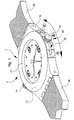
- FIG. 1 in which is represented a timepiece according to the invention, designated as a whole by the general reference numeral 1.
- the timepiece 1 conventionally comprises a housing 2 made for example of a plastic material according to a well-known injection technique.
- the timepiece 1 further comprises a horometric movement (not shown) housed inside the housing 2 and coupled to indicators 4, 6 and 8 respectively forming an hour hand, a minute hand and a second hand .
- a horometric movement housed inside the housing 2 and coupled to indicators 4, 6 and 8 respectively forming an hour hand, a minute hand and a second hand .
- the timepiece 1 is sealed by means of a lens 10 and a window 12.
- the latter is fixedly mounted on the housing 2, for example by gluing or by ultrasonic welding.
- the casing 2 comprises a middle part 14 which carries in particular a winding crown 16, for example to reassemble the horometric movement of the timepiece 1 or to adjust the display of the indicators 4, 6 and 8.
- the strands 18 and 20 of a bracelet (not shown) are fixed on the middle part 14 of the casing 2.
- the middle part 14 of the housing 2 carries, in addition to the winding crown 16, selection and activation means 22 of the desired service.
- these selection and activation means 22 are in the form of a manually operable switch 24, and slidingly moving in a guide groove 26 formed in the middle part 14 of the casing 2, opposite the winding crown 16.
- the switch 24 can be moved for example between three different positions designated by the alphabetical references A , B and C in Figure 1. Each of these three positions A , B and C corresponds to the selection and activation of a service particular, for example access to ski lifts of a winter sports resort, unlocking the room of a hotel door or even the payment of a cinema ticket.
- a service for example access to ski lifts of a winter sports resort, unlocking the room of a hotel door or even the payment of a cinema ticket.
- it can, for example, engrave on the ice 10 of the timepiece 1 a code or an indication to identify visually which service corresponds to the position of the switch 24 which he has chosen.
- the present invention is not limited to a given number of services or a specific type of service (ski, hotel, cinema, banking transactions or the like).
- the selection and activation means 22 it is conceivable to give the selection and activation means 22 a shape other than that of a switch 24. It may in particular be a pusher crown.
- each module 28, 30 or 32 corresponds to a particular service and is inserted in an independent electrical circuit, respectively 34, 36 and 38.
- these electrical circuits 34, 36 and 38 are normally in the open state . Only the movement of the switch 24 of one of the positions A , B or C to the next or previous position can control the displacement of the electrical contact piece 26 which then electrically closes the circuit 34, 36 or 38 in which is inserted the electronic module, respectively 28, 30 or 32, corresponding to the chosen service.
- the circuit 34, 36 or 38 is electrically closed by the contact piece 26 the energy required for the operation of the corresponding electronic module 28, 30 or 32 is provided by the electromagnetic waves emitted by the external control terminal provided for the identification of the timepiece 1.
- the electronic module 28 is electrically connected to a first antenna 40 whose resonant frequency can be adjusted to 125 kHz.
- This frequency is particularly well suited to services that do not require a great deal of security in transactions between the portable object and the external control terminal (ski lifts, for example), nor important data exchange flows.
- the portable object can be quite far from the external control terminal during the transaction, typically of the order of 20 to 50 cm.
- the electronic modules 30 and 32 are electrically connected in parallel with a second antenna 42 whose resonance frequency can be set at 13.56 MHz. This frequency is well suited to services requiring significant transaction security (banking transactions in particular) and involving significant data exchange.
- the present invention is not limited to particular frequencies, and that there can be provided as many antennas as there are modules in the case of the portable object.
- the electronic module 28 electrically connected to the antenna 40 whose resonance frequency is set at 125 kHz may be constituted by an integrated circuit marketed by the company EM Microelectronic SA in Marin, Switzerland, under the reference V4050 .
- V4050 the electronic module 28 electrically connected to the antenna 40 whose resonance frequency is set at 125 kHz
- all the electronic modules from the various manufacturers present on the market at the moment can be associated with the case 2 of the timepiece 1.
- the antenna 40 is electrically connected to an AC / DC converter CONV which transforms the alternating electromagnetic radiation captured by the antenna 40 into a continuous internal supply voltage of the integrated circuit.
- a power control device POW ensures that the level of the internal DC voltage supplied by the converter CONV is sufficient to allow the proper functioning of the integrated circuit.
- the signal picked up by the antenna 40 is also demodulated and decoded by a data extraction string DATA and a CLOCK clock signal chain to supply the logic levels and the internal frequency to a control logic circuit CTRL .
- the control logic circuit CTRL governs the operation of the integrated circuit. It provides the system with a high level of operational security, including a 32-bit password and a protected read-only zone for security organization. Each control logic circuit CTRL is unique and differs from others by an identification number and a serial number programmed by laser into a ROM-type memory.
- the control circuit CTRL also contains an algorithm that makes it possible to encode transactions and thus increase the security of the system vis-à-vis any attempt at fraudulent use. It also protects the data recorded in reading and writing. Finally, the control circuit CTRL makes it possible to choose between different modes of operation of the integrated circuit in which it is implanted.
- each integrated circuit is provided with a 1 kbit EEPROM type MEM memory.
- the electronic circuit retransmits the information to the external control terminal in the form of bit signals via an encoding device ENC and a modulator MOD .
Abstract
Description
La présente invention concerne un objet portatif, en particulier une pièce d'horlogerie, comprenant un boîtier auquel est associé un module électronique destiné à permettre la communication sans contact et sans fil entre l'objet portatif et un terminal externe prévu à cet effet.The present invention relates to a portable object, in particular a timepiece, comprising a housing with which is associated an electronic module for enabling contactless and wireless communication between the portable object and an external terminal provided for this purpose.
La présente invention vise une multitude de situations ou d'endroits où l'on contrôle par exemple qu'une personne possède un droit d'accès payant ou non.The present invention relates to a multitude of situations or places where it controls for example that a person has a paid access right or not.
L'invention vise notamment les systèmes de contrôle d'accès à des sites industriels (laboratoires de recherche et de développement, unités de production etc.) et à des édifices publics (stades, musées, cinémas ou analogues) dans lesquels l'objet portatif est présenté par son détenteur à un dispositif de contrôle qui n'autorise l'accès au site ou à l'édifice que si l'information mémorisée dans l'objet porté par la personne correspond à une autorisation d'accès, le paiement d'un montant suffisant ou encore une date limite de validité convenable.The invention is aimed in particular at systems for controlling access to industrial sites (research and development laboratories, production units, etc.) and at public buildings (stadiums, museums, cinemas or the like) in which the portable object is presented by its holder to a control device that authorizes access to the site or building only if the information stored in the object carried by the person corresponds to an access authorization, the payment of a sufficient amount or a valid expiry date.
On connaît des systèmes de contrôle d'accès qui mettent en oeuvre des cartes pourvues d'une piste magnétique propres à être introduites dans la fente d'un terminal de contrôle d'accès à l'intérieur duquel les informations portées par la piste magnétique sont lues. Lorsque ces informations sont reconnues, une autorisation d'accès est délivrée et de nouvelles informations peuvent être inscrites sur la piste magnétique.Access control systems are known which use cards provided with a magnetic strip adapted to be introduced into the slot of an access control terminal inside which the information carried by the magnetic strip is read. When this information is recognized, an access authorization is issued and new information can be entered on the magnetic strip.
Les systèmes de contrôle d'accès à carte magnétique sont cependant parfois d'une utilisation peu aisée, notamment en raison de l'étroitesse de la fente dans laquelle la carte doit être insérée pour la lecture précise de son contenu. Ainsi, lorsqu'un système de contrôle d'accès à carte magnétique est utilisé sur certains équipements tels que, par exemple, des remontées mécaniques dans les stations de sports d'hiver, le maniement de la carte magnétique par des utilisateurs dont les mains ne sont pas libres s'avère particulièrement lent et mal commode. D'autre part, l'introduction répétée de la carte dans la fente du terminal provoque l'usure de la piste magnétique sur laquelle sont stockées les informations utiles.Magnetic card access control systems are however sometimes not very easy to use, particularly because of the narrowness of the slot in which the card must be inserted for the precise reading of its contents. So when a magnetic card access control system is used on some equipment such as, for example, ski lifts in winter sports resorts, the handling of the magnetic card by users whose hands are not free is particularly slow and inconvenient. On the other hand, the repeated insertion of the card into the slot of the terminal causes the wear of the magnetic strip on which the useful information is stored.
Pour remédier à cet inconvénient, il a été proposé un système de contrôle et d'identification automatique d'objets dans lequel un objet portatif renferme, dans un boîtier, un module électronique comportant notamment une mémoire pour enregistrer des informations utiles telles qu'un code d'identification, un dispositif d'émission et de réception de signaux radiodiffusés, et une antenne reliée électriquement au dispositif d'émission/réception. Dans ce système de contrôles d'objets, le dispositif d'émission/réception est capable, lorsqu'il est couplé avec un terminal externe prévu à cet effet, d'émettre des signaux radiodiffusés correspondant à la lecture des informations enregistrées dans le circuit mémoire et, le cas échéant, de recevoir des signaux radiodiffusés pour la réinscription de nouvelles informations utiles dans ce circuit mémoire. Ainsi, lorsque le terminal externe émet un signal d'interrogation, la détection de ce signal par l'objet portatif entraîne la transmission, par exemple d'un code d'identification de cet objet, ce qui permet ensuite au terminal d'identifier cet objet et par conséquent de contrôler l'identité de son porteur.To remedy this drawback, it has been proposed a system for controlling and automatically identifying objects in which a portable object contains, in a housing, an electronic module including a memory for recording useful information such as a code identification device, a device for transmitting and receiving broadcast signals, and an antenna electrically connected to the transmitting / receiving device. In this object control system, the transmission / reception device is capable, when coupled with an external terminal provided for this purpose, of transmitting broadcast signals corresponding to the reading of the information recorded in the memory circuit. and, if necessary, receive broadcast signals for the re-registration of new useful information in this memory circuit. Thus, when the external terminal transmits an interrogation signal, the detection of this signal by the portable object causes the transmission, for example of an identification code of this object, which then allows the terminal to identify this object and therefore to control the identity of its bearer.
Le système d'identification automatique d'objets ci-dessus procure de nombreux avantages.The Automatic Object Identification System above provides many benefits.
Les contrôles d'accès, payants ou non, sont rendus plus aisés et plus rapides. En effet, les informations nécessaires d'identification ou autres sont écrites et lues en mémoire sans contact et sans fil. Ainsi, par exemple, l'opération d'introduction mécanique d'une carte dans la fente d'un lecteur, rendue souvent délicate par les circonstances, est supprimée. D'autre part, ce système est entièrement passif, c'est-à-dire qu'il ne nécessite aucune source d'énergie propre. L'énergie nécessaire à son fonctionnement est fournie par les ondes électromagnétiques qu'émet le terminal pour l'identification de l'objet.Access controls, whether paid or not, are made easier and faster. Indeed, the necessary identification or other information is written and read in contactless and wireless memory. Thus, for example, the operation of mechanical introduction of a card into the slot of a reader, often made difficult by circumstances, is removed. On the other hand, this system is entirely passive, that is to say it does not require any source of clean energy. The energy required for its operation is provided by the electromagnetic waves emitted by the terminal for the identification of the object.
A l'heure actuelle, cependant, les différents fabricants présents sur le marché proposent des systèmes de contrôle sans contact d'objets qui diffèrent les uns des autres notamment par la structure des modules électroniques utilisés dans les objets à contrôler, ce qui rend ces systèmes totalement incompatibles entre eux. L'utilisateur se trouve donc dans l'obligation d'acquérir, pour chaque service recherché, par exemple pour les remontées mécaniques de plusieurs stations de ski, pour l'ouverture de la porte d'une chambre d'hôtel comme pour les paiements au bar de celui-ci, l'objet qui lui correspond. On le comprendra facilement, une telle situation est peu commode pour l'utilisateur. Elle multiplie le nombre d'objets portatifs, augmente les risques de vol, de perte ou d'oubli de ces objets, et entraîne un accroissement considérable des coûts.At present, however, the various manufacturers on the market offer contactless control systems of objects that differ from each other in particular by the structure of the electronic modules used in the objects to be controlled, which makes these systems totally incompatible with each other. The user is therefore obliged to purchase, for each service sought, for example for the ski lifts of several ski resorts, for the opening of the door of a hotel room as for payments to the hotel. bar of it, the object that corresponds to it. It will be understood easily, such a situation is inconvenient for the user. It multiplies the number of portable objects, increases the risk of theft, loss or forgetfulness of these objects, and causes a considerable increase in costs.
On connaît par la demande de brevet allemand DE-A-3740794 une montre-bracelet électronique qui autorise la communication interactive avec d'autres systèmes tels que la banque. Plus précisément, ce document décrit un système de gestion et de stockage de données personnelles renfermé dans une boîte de montre et qui peut être utilisé pour la communication avec d'autres systèmes. Typiquement, l'unité peut communiquer avec le système bancaire et se substitue aux cartes de crédit ou aux cartes bancaires. L'unité comprend des moyens d'entrée/sortie par exemple du type opto-électronique ou électro-acoustique. Un clavier miniature permet d'entrer des commandes de transmission d'informations. L'unité comprend un microprocesseur pour permettre l'interprétation d'informations codées. Ce document ne décrit ni ne suggère des moyens de sélection et d'activation de fonctions d'échange de données opérant à des fréquences différentes.DE-A-3740794 discloses an electronic wristwatch which allows interactive communication with other systems such as the bank. More specifically, this document describes a system for managing and storing personal data contained in a watch case and which can be used for communication with other systems. Typically, the unit can communicate with the banking system and substitute for credit cards or bank cards. The unit comprises input / output means for example of the opto-electronic or electro-acoustic type. A miniature keyboard is used to enter information transmission commands. The unit includes a microprocessor for enabling interpretation of coded information. This document describes or suggests means for selecting and activating data exchange functions operating at different frequencies.
La présente invention a pour but de remédier aux problèmes et inconvénients décrits ci-dessus en proposant un objet portatif, en particulier une montre-bracelet, qui permette de sélectionner personnellement et simultanément une pluralité de services différents.The object of the present invention is to remedy the problems and disadvantages described above by proposing a portable object, in particular a wristwatch, which makes it possible to personally and simultaneously select a plurality of different services.
A cet effet, l'invention concerne un objet portatif pour systèmes de contrôle d'accès sans contact, comprenant un boîtier auquel est associée au moins une antenne, caractérisé en ce que le boîtier comporte au moins deux modules électroniques différents, chaque module électronique permettant l'accès à un service particulier, l'objet portatif comprenant d'autre part des moyens de sélection et d'activation de l'un desdits modules électroniques en fonction du service souhaité par l'utilisateur.For this purpose, the invention relates to a portable object for contactless access control systems, comprising a housing with which at least one antenna is associated, characterized in that the housing comprises at least two different electronic modules, each electronic module enabling access to a particular service, the portable object further comprising means for selecting and activating one of said electronic modules according to the service desired by the user.
Grâce aux caractéristiques de la présente invention, l'utilisateur peut accéder, simultanément et avec une grande aisance, à une pluralité de services différents, par exemple accès aux remontées mécaniques de plusieurs stations de sports d'hiver, ouverture de la porte d'une chambre d'hôtel, paiement d'une place de cinéma et autres, à l'aide d'un unique objet portatif. Les risques de perte, de vol ou d'oubli de l'objet sont minimisés, et les coûts réduits.Thanks to the characteristics of the present invention, the user can access, simultaneously and with great ease, a plurality of different services, for example access to ski lifts of several winter sports resorts, opening the door of a hotel room, payment of a cinema seat and the like, using a single portable object. The risks of loss, theft or forgetting of the object are minimized, and the costs reduced.
Selon une caractéristique avantageuse de l'invention, les moyens de sélection et d'activation commandent le déplacement d'une pièce de contact électrique pour la mise en circuit de celui des modules électroniques qui correspond au service recherché par l'utilisateur.According to an advantageous characteristic of the invention, the selection and activation means control the movement of an electrical contact piece for switching on that of the electronic modules which corresponds to the service sought by the user.
D'autres caractéristiques et avantages de la présente invention apparaîtront plus clairement à la lecture de la description suivante d'un mode de réalisation de l'invention, donné à titre purement illustratif et non limitatif, cette description étant faite en liaison avec les dessins annexés dans lesquels :
- la figure 1 est une vue en perspective d'une montre-bracelet selon l'invention comprenant des moyens de sélection et d'activation des modules électroniques ;
- la figure 2 est un schéma électrique de raccordement des modules électroniques correspondant aux différents services souhaités sur lequel est représentée la pièce de contact électrique permettant la mise en circuit ou hors circuit de ces modules, et
- la figure 3 est une représentation schématique des différents blocs fonctionnels constituant un module électronique.
- Figure 1 is a perspective view of a wristwatch according to the invention comprising means for selecting and activating the electronic modules;
- FIG. 2 is an electrical wiring diagram of the electronic modules corresponding to the different desired services on which is represented the electrical contact piece allowing these modules to be switched on or off, and
- Figure 3 is a schematic representation of the various functional blocks constituting an electronic module.
On notera dès à présent que la présente invention n'est pas limitée à des plages de fréquence particulières pour les antennes intégrées dans le boîtier, et n'est également pas limitée à des services spécifiques. D'autre part, bien que la description suivante concerne des pièces d'horlogerie, en particulier une montre-bracelet, la présente invention n'est pas limitée à de telles pièces, et peut aisément s'appliquer à tout autre objet portatif dans lequel sont agencés au moins deux modules électroniques permettant la réception et l'émission de signaux radiodiffusés correspondant à la lecture d'informations enregistrées dans un circuit mémoire, et le cas échéant la réinscription de nouvelles informations utiles dans ce circuit mémoire.It will now be appreciated that the present invention is not limited to particular frequency ranges for antennas integrated into the housing, and is also not limited to specific services. On the other hand, although the following description relates to timepieces, in particular a wristwatch, the present invention is not limited to such parts, and can easily be applied to any other portable object in which are arranged at least two electronic modules for receiving and transmitting broadcast signals corresponding to the reading of information stored in a memory circuit, and if necessary the re-registration of new useful information in this memory circuit.
On se reportera tout d'abord à la figure 1 sur laquelle est représentée une pièce d'horlogerie selon l'invention, désignée dans son ensemble par la référence numérique générale 1.Reference is first made to FIG. 1, in which is represented a timepiece according to the invention, designated as a whole by the general reference numeral 1.
La pièce d'horlogerie 1 comporte de façon classique un boîtier 2 réalisé par exemple en un matériau plastique selon une technique d'injection bien connue.The timepiece 1 conventionally comprises a
La pièce d'horlogerie 1 comporte en outre un mouvement horométrique (non représenté) logé à l'intérieur du boîtier 2 et couplé à des indicateurs 4, 6 et 8 formant respectivement une aiguille des heures, une aiguille des minutes et une aiguille des secondes.The timepiece 1 further comprises a horometric movement (not shown) housed inside the
La pièce d'horlogerie 1 est rendue étanche au moyen d'une glace 10 et d'une lunette 12. Cette dernière est montée fixe sur le boîtier 2, par exemple par collage ou par soudage aux ultrasons.The timepiece 1 is sealed by means of a
Le boîtier 2 comprend une carrure 14 qui porte notamment une couronne de remontoir 16, par exemple pour remonter le mouvement horométrique de la pièce d'horlogerie 1 ou pour régler l'affichage des indicateurs 4, 6 et 8.The
Les brins 18 et 20 d'un bracelet (non représenté) sont fixés sur la carrure 14 du boîtier 2.The
Conformément à l'invention, la carrure 14 du boîtier 2 porte, outre la couronne de remontoir 16, des moyens de sélection et d'activation 22 du service souhaité.According to the invention, the
Dans l'exemple représenté à la figure 1, ces moyens de sélection et d'activation 22 se présentent sous la forme d'un commutateur 24, actionnable manuellement, et se déplaçant à coulissement dans une rainure-guide 26 formée dans la carrure 14 du boîtier 2, à l'opposé de la couronne de remontoir 16.In the example shown in FIG. 1, these selection and activation means 22 are in the form of a manually
Le commutateur 24 peut être déplacé par exemple entre trois positions différentes désignées par les références alphabétiques A, B et C sur la figure 1. Chacune de ces trois positions A, B et C correspond à la sélection et à l'activation d'un service particulier, par exemple l'accès aux remontées mécaniques d'une station de sports d'hiver, le déverrouillage de la chambre d'une porte d'hôtel ou bien encore le paiement d'une place de cinéma. Pour simplifier la tâche de l'utilisateur, et lui permettre de sélectionner rapidement le service qu'il désire, on peut, par exemple, graver sur la glace 10 de la pièce d'horlogerie 1 un code ou une indication permettant d'identifier visuellement à quel service correspond la position du commutateur 24 qu'il a choisie.The
Il est bien entendu que la présente invention n'est pas limitée à un nombre donné de services, ni à un type déterminé de services (ski, hôtel, cinéma, transactions bancaires ou analogue). D'autre part, on peut imaginer de donner aux moyens de sélection et d'activation 22 une autre forme que celle d'un commutateur 24. Il peut notamment s'agir d'une couronne à poussoir. De même, on peut envisager d'afficher le code ou l'indication permettant d'identifier le service choisi au moyen d'une cellule à affichage électro-optique.It is understood that the present invention is not limited to a given number of services or a specific type of service (ski, hotel, cinema, banking transactions or the like). On the other hand, it is conceivable to give the selection and activation means 22 a shape other than that of a
Le déplacement du commutateur 24 de l'une de ses positions de sélection/activation A, B ou C à la position suivante ou précédente provoque le déplacement correspondant d'une pièce de contact électrique 26 (figure 2), ce qui entraîne la mise en circuit de celui des trois modules électroniques 28, 30 ou 32 qui correspond au service sélectionné au moyen dudit commutateur 24.The movement of the
Plus précisément, les trois modules électroniques 28, 30 et 32 sont logés dans le boîtier 2 de la pièce d'horlogerie 1. Comme on l'aura bien compris, chaque module 28, 30 ou 32 correspond à un service particulier et est inséré dans un circuit électrique indépendant, respectivement 34, 36 et 38. Comme il ressort de la figure 2, ces circuits électriques 34, 36 et 38 sont normalement à l'état ouvert. Seul le déplacement du commutateur 24 de l'une des positions A, B ou C vers la position suivante ou précédente peut commander le déplacement de la pièce de contact électrique 26 qui vient alors fermer électriquement le circuit 34, 36 ou 38 dans lequel est inséré le module électronique, respectivement 28, 30 ou 32, correspondant au service choisi. Lorsque le circuit 34, 36 ou 38 est électriquement fermé par la pièce de contact 26, l'énergie nécessaire au fonctionnement du module électronique 28, 30 ou 32 correspondant est fournie par les ondes électromagnétiques qu'émet le terminal de contrôle externe prévu pour l'identification de la pièce d'horlogerie 1.More precisely, the three
Le module électronique 28 est relié électriquement à une première antenne 40 dont la fréquence de résonance peut être ajustée à 125 kHz. Cette fréquence est particulièrement bien adaptée aux services ne nécessitant ni une grande sécurité dans les transactions entre l'objet portatif et le terminal de contrôle externe (remontées mécaniques par exemple), ni des flux d'échange de données importants. Avantageusement, l'objet portatif peut être assez éloigné du terminal de contrôle externe lors de la transaction, typiquement de l'ordre de 20 à 50 cm.The
Toujours à titre d'exemple illustratif seulement, les modules électroniques 30 et 32 sont reliés électriquement en parallèle à une seconde antenne 42 dont la fréquence de résonance peut être fixée à 13,56 MHz. Cette fréquence est bien adaptée aux services nécessitant une sécurité de transaction importante (transactions bancaires notamment) et impliquant des échanges de données importants.Still as an illustrative example only, the
Il va de soi que la présente invention n'est pas limitée à des fréquences particulières, et qu'il peut être prévu autant d'antennes qu'il existe de modules électroniques dans le boîtier de l'objet portatif. D'autre part, on peut également prévoir de loger les modules électroniques 28, 30, 32 et leurs antennes 40, 42 par exemple dans la lunette 12 du boîtier 2.It goes without saying that the present invention is not limited to particular frequencies, and that there can be provided as many antennas as there are modules in the case of the portable object. On the other hand, it is also possible to house the
A titre d'exemple, le module électronique 28 relié électriquement à l'antenne 40 dont la fréquence de résonance est fixée à 125 kHz peut être constitué par un circuit intégré commercialisé par la société EM Microelectronic SA à Marin, Suisse, sous la référence V4050. On comprendra néanmoins que, conformément à l'invention, tous les modules électroniques provenant des différents fabricants présents sur le marché à l'heure actuelle peuvent être associés au boîtier 2 de la pièce d'horlogerie 1.By way of example, the
On examine maintenant en référence à la figure 3 les différents blocs fonctionnels qui constituent un tel circuit intégré.We now examine with reference to Figure 3 the various functional blocks that constitute such an integrated circuit.
L'antenne 40 est reliée électriquement à un convertisseur courant alternatif/courant continu CONV qui transforme le rayonnement électromagnétique alternatif capté par l'antenne 40 en une tension interne continue d'alimentation du circuit intégré.The
Un dispositif de commande de puissance POW s'assure que le niveau de la tension continue interne fournie par le convertisseur CONV est suffisant pour permettre le bon fonctionnement du circuit intégré.A power control device POW ensures that the level of the internal DC voltage supplied by the converter CONV is sufficient to allow the proper functioning of the integrated circuit.
Le signal capté par l'antenne 40 est également démodulé et décodé par une chaîne d'extraction de données DATA et une chaîne de signal d'horloge CLOCK pour fournir les niveaux logiques et la fréquence interne à un circuit logique de commande CTRL.The signal picked up by the
Le circuit logique de commande CTRL gouverne le fonctionnement du circuit intégré. Il procure une grande sécurité de fonctionnement au système grâce, notamment, à un mot de passe de 32 bits et une zone protégée en lecture pour l'organisation de la sécurité. Chaque circuit logique de commande CTRL est unique et se distingue des autres par un numéro d'identification et un numéro de série programmés par laser dans une mémoire de type ROM.The control logic circuit CTRL governs the operation of the integrated circuit. It provides the system with a high level of operational security, including a 32-bit password and a protected read-only zone for security organization. Each control logic circuit CTRL is unique and differs from others by an identification number and a serial number programmed by laser into a ROM-type memory.
Le circuit de commande CTRL renferme également un algorithme qui permet de coder les transactions et donc d'accroître la sécurité du système vis-à-vis de toute tentative d'utilisation frauduleuse. Il assure aussi la protection des données enregistrées en lecture et en écriture. Enfin, le circuit de commande CTRL permet de choisir entre différents modes de fonctionnement du circuit intégré dans lequel il est implanté.The control circuit CTRL also contains an algorithm that makes it possible to encode transactions and thus increase the security of the system vis-à-vis any attempt at fraudulent use. It also protects the data recorded in reading and writing. Finally, the control circuit CTRL makes it possible to choose between different modes of operation of the integrated circuit in which it is implanted.
Pour l'enregistrement des informations utiles, chaque circuit intégré est doté d'une mémoire MEM de type EEPROM de 1 kBits.For the recording of useful information, each integrated circuit is provided with a 1 kbit EEPROM type MEM memory.
Finalement, le circuit électronique retransmet les informations vers le terminal de contrôle externe sous forme de signaux de bits via un dispositif de codage ENC et un modulateur MOD.Finally, the electronic circuit retransmits the information to the external control terminal in the form of bit signals via an encoding device ENC and a modulator MOD .
Il va de soi qu'au delà des moyens décrits, diverses variantes et modifications simples entrent dans le cadre de la présente invention.It goes without saying that beyond the means described, various variants and simple modifications are within the scope of the present invention.
Claims (7)
- Portable object for contactless access control systems, including a case (2) with which at least one antenna (40, 42) is associated, characterized in that the case (2) includes at least two different electronic modules (28, 30, 32), each module (28, 30, 32) allowing access to a particular service, the portable object also including means (22) for selecting and activating one of said electronic modules (28, 30, 32) as a function of the service desired by the user.
- Portable object according to claim 1, characterized in that the selection and activation means (22) control the movement of an electric contact member (26) for the connection of the electronic module (28, 30, 32) which corresponds to the service sought by the user.
- Portable object according to claim 2, characterized in that each electronic module (28, 30, 32) is inserted into an independent electric circuit (34, 36, 38), these electric circuits (34, 36, 38) being normally in the open state, the electric contact member (26) closing the electric circuit (34, 36, 38) in which the electronic module (28, 30, 32) corresponding to the service selected by the user is inserted.
- Portable object according to any one of the preceding claims, characterized in that the selection and activation means (22) take the form of a switch (24) able to be actuated manually, and sliding in a guide-groove (26).
- Portable object according to any one of the preceding claims, characterized in that the resonance frequency of the antenna (40, 42) is set at 125 kHz.
- Portable object according to any one of claims 1 to 5, characterized in that the resonance frequency of the antenna (40, 42) is set at 13.56 MHz.
- Portable object according to any one of the preceding claims, characterized in that the electronic module (28) electrically connected to the antenna (40) whose resonance frequency is set at 125 kHz is formed by an integrated circuit.
Priority Applications (3)
| Application Number | Priority Date | Filing Date | Title |
|---|---|---|---|
| DE69737390T DE69737390T2 (en) | 1997-11-28 | 1997-11-28 | Portable object, especially clock with several selectable electronic modules |
| AT97120899T ATE354839T1 (en) | 1997-11-28 | 1997-11-28 | WEARABLE OBJECT, ESPECIALLY A WATCH WITH MULTIPLE SELECTABLE ELECTRONIC MODULES |
| EP97120899A EP0919959B1 (en) | 1997-11-28 | 1997-11-28 | Portable object, in particular a watch, containing multiple selectable electronic modules |
Applications Claiming Priority (1)
| Application Number | Priority Date | Filing Date | Title |
|---|---|---|---|
| EP97120899A EP0919959B1 (en) | 1997-11-28 | 1997-11-28 | Portable object, in particular a watch, containing multiple selectable electronic modules |
Publications (2)
| Publication Number | Publication Date |
|---|---|
| EP0919959A1 EP0919959A1 (en) | 1999-06-02 |
| EP0919959B1 true EP0919959B1 (en) | 2007-02-21 |
Family
ID=8227696
Family Applications (1)
| Application Number | Title | Priority Date | Filing Date |
|---|---|---|---|
| EP97120899A Expired - Lifetime EP0919959B1 (en) | 1997-11-28 | 1997-11-28 | Portable object, in particular a watch, containing multiple selectable electronic modules |
Country Status (3)
| Country | Link |
|---|---|
| EP (1) | EP0919959B1 (en) |
| AT (1) | ATE354839T1 (en) |
| DE (1) | DE69737390T2 (en) |
Families Citing this family (5)
| Publication number | Priority date | Publication date | Assignee | Title |
|---|---|---|---|---|
| EP1168113A1 (en) * | 2000-06-20 | 2002-01-02 | The Swatch Group Management Services AG | Device for commutating between at least three different electric contacts |
| TW535037B (en) | 2000-06-20 | 2003-06-01 | Swatch Group Man Serv Ag | Electric device for switching between at least three different contacts |
| JP2002257955A (en) | 2000-12-25 | 2002-09-11 | Seiko Epson Corp | Wristwatch device with communication function, method of displaying information, control program and recording medium |
| EP3835887B1 (en) * | 2019-12-10 | 2022-07-13 | The Swatch Group Research and Development Ltd | Watch provided with a controller |
| EP3835886B1 (en) * | 2019-12-10 | 2022-08-10 | The Swatch Group Research and Development Ltd | Watch provided with a controller |
Family Cites Families (7)
| Publication number | Priority date | Publication date | Assignee | Title |
|---|---|---|---|---|
| JPS5273070A (en) * | 1975-12-15 | 1977-06-18 | Seiko Epson Corp | Multi-function fully-electronic wrist watch |
| JPS55121179A (en) * | 1979-03-09 | 1980-09-18 | Rhythm Watch Co Ltd | Electronic watch |
| US5202550A (en) * | 1986-10-23 | 1993-04-13 | Skidata Computer Gesellschaft M.B.H. | Device for machine communication in data transmission |
| DE3740794A1 (en) * | 1987-12-02 | 1989-06-15 | Pedro Rodriguez | Electronic data-processing wristwatch as interactive wireless data carrier and control element |
| US5049728A (en) * | 1990-04-04 | 1991-09-17 | Rovin George H | IC card system with removable IC modules |
| DE4015685C2 (en) * | 1990-05-16 | 1996-11-28 | Schickedanz Willi | watch |
| JP3694883B2 (en) * | 1996-03-19 | 2005-09-14 | ソニー株式会社 | Locking / unlocking control device |
-
1997
- 1997-11-28 EP EP97120899A patent/EP0919959B1/en not_active Expired - Lifetime
- 1997-11-28 DE DE69737390T patent/DE69737390T2/en not_active Expired - Lifetime
- 1997-11-28 AT AT97120899T patent/ATE354839T1/en not_active IP Right Cessation
Also Published As
| Publication number | Publication date |
|---|---|
| ATE354839T1 (en) | 2007-03-15 |
| DE69737390T2 (en) | 2007-10-31 |
| EP0919959A1 (en) | 1999-06-02 |
| DE69737390D1 (en) | 2007-04-05 |
Similar Documents
| Publication | Publication Date | Title |
|---|---|---|
| EP0670556B1 (en) | Portable device for functional link between an IC card and a central unit | |
| CA2382083C (en) | Contact-free display peripheral device for contact-free portable object | |
| FR2501396A1 (en) | ACCESS CONTROL SYSTEM, PARTICULARLY FOR PASSING TOLL POINTS | |
| EP2065857A2 (en) | Microprocessor card, telephone comprising such a card and method of executing a command on such a card | |
| EP1857953A1 (en) | Method and system for authentication and secure exchange of data between a personalised chip and a dedicated server | |
| AU755269B2 (en) | Portable object, in particular a watch, including multiple selectable electronic modules | |
| IL96764A (en) | Smart card integrated in a wristwatch and having logic unit controlling the automatic identification process and the data transfer | |
| FR2635889A1 (en) | PORTABLE INDUCTION POWERABLE MEMORY DEVICE | |
| EP1043680A1 (en) | Very close-coupled electromagnetic transponder | |
| LU87332A1 (en) | TRAFFIC CONTROL SYSTEM FOR MOBILE COMPONENTS AND / OR MOVING PERSONS, THIS SYSTEM USING A FIXED STATION AND A PROGRAMMABLE COMPONENT CARRIED BY SUCH COMPONENTS AND / OR PERSONS | |
| EP1043677A1 (en) | Reader for electromagnetic transponders which functions with very short distance coupling | |
| WO2003056510A1 (en) | Non-contact portable object comprising at least a peripheral device connected to the same antenna as the chip | |
| EP0919959B1 (en) | Portable object, in particular a watch, containing multiple selectable electronic modules | |
| EP2065859A2 (en) | Microprocessor card, telephone comprising such a card and processing method on such a card | |
| FR2663145A1 (en) | "Hands-free" device for remote identification | |
| FR2637710A1 (en) | Method and device for high-security multifunction electronic control comprising a microchip card | |
| EP1484715A2 (en) | Smart card | |
| FR2686997A1 (en) | TWO - CONTACTING CHIP CARD AND METHOD FOR COMMUNICATING WITH A CARD READER. | |
| EP1857966B1 (en) | Portable device with an ID tag that might be interrogated by an external reader | |
| EP1213629A1 (en) | Portable object, in particular time piece, containing a waterproof container mounted within metal case | |
| EP1559066A2 (en) | Rfid-uhf integrated circuit | |
| FR2556115A1 (en) | IMPROVEMENTS ON CODE CONTROL DEVICES | |
| EP0786747B1 (en) | Virtual IC-card for payments | |
| FR2616938A1 (en) | Device for reading an electronic card of the credit card type | |
| FR2522850A2 (en) | Portable payment control system for toll points - uses portable memory with associated contactless communicator for use at control terminals which decrease prepaid amount stored in memory |
Legal Events
| Date | Code | Title | Description |
|---|---|---|---|
| PUAI | Public reference made under article 153(3) epc to a published international application that has entered the european phase |
Free format text: ORIGINAL CODE: 0009012 |
|
| AK | Designated contracting states |
Kind code of ref document: A1 Designated state(s): AT CH DE ES FI FR GB IT LI NL SE |
|
| 17P | Request for examination filed |
Effective date: 19991202 |
|
| AKX | Designation fees paid |
Free format text: AT CH DE ES FI FR GB IT LI NL SE |
|
| RAP1 | Party data changed (applicant data changed or rights of an application transferred) |
Owner name: ETA SA MANUFACTURE HORLOGERE SUISSE |
|
| 17Q | First examination report despatched |
Effective date: 20041005 |
|
| GRAP | Despatch of communication of intention to grant a patent |
Free format text: ORIGINAL CODE: EPIDOSNIGR1 |
|
| GRAS | Grant fee paid |
Free format text: ORIGINAL CODE: EPIDOSNIGR3 |
|
| GRAA | (expected) grant |
Free format text: ORIGINAL CODE: 0009210 |
|
| AK | Designated contracting states |
Kind code of ref document: B1 Designated state(s): AT CH DE ES FI FR GB IT LI NL SE |
|
| PG25 | Lapsed in a contracting state [announced via postgrant information from national office to epo] |
Ref country code: NL Free format text: LAPSE BECAUSE OF FAILURE TO SUBMIT A TRANSLATION OF THE DESCRIPTION OR TO PAY THE FEE WITHIN THE PRESCRIBED TIME-LIMIT Effective date: 20070221 Ref country code: FI Free format text: LAPSE BECAUSE OF FAILURE TO SUBMIT A TRANSLATION OF THE DESCRIPTION OR TO PAY THE FEE WITHIN THE PRESCRIBED TIME-LIMIT Effective date: 20070221 Ref country code: AT Free format text: LAPSE BECAUSE OF FAILURE TO SUBMIT A TRANSLATION OF THE DESCRIPTION OR TO PAY THE FEE WITHIN THE PRESCRIBED TIME-LIMIT Effective date: 20070221 |
|
| REG | Reference to a national code |
Ref country code: GB Ref legal event code: FG4D Free format text: NOT ENGLISH |
|
| REG | Reference to a national code |
Ref country code: CH Ref legal event code: EP |
|
| REF | Corresponds to: |
Ref document number: 69737390 Country of ref document: DE Date of ref document: 20070405 Kind code of ref document: P |
|
| PG25 | Lapsed in a contracting state [announced via postgrant information from national office to epo] |
Ref country code: SE Free format text: LAPSE BECAUSE OF FAILURE TO SUBMIT A TRANSLATION OF THE DESCRIPTION OR TO PAY THE FEE WITHIN THE PRESCRIBED TIME-LIMIT Effective date: 20070521 |
|
| PG25 | Lapsed in a contracting state [announced via postgrant information from national office to epo] |
Ref country code: ES Free format text: LAPSE BECAUSE OF FAILURE TO SUBMIT A TRANSLATION OF THE DESCRIPTION OR TO PAY THE FEE WITHIN THE PRESCRIBED TIME-LIMIT Effective date: 20070601 |
|
| GBT | Gb: translation of ep patent filed (gb section 77(6)(a)/1977) |
Effective date: 20070523 |
|
| REG | Reference to a national code |
Ref country code: CH Ref legal event code: NV Representative=s name: ICB INGENIEURS CONSEILS EN BREVETS SA |
|
| NLV1 | Nl: lapsed or annulled due to failure to fulfill the requirements of art. 29p and 29m of the patents act | ||
| PLBE | No opposition filed within time limit |
Free format text: ORIGINAL CODE: 0009261 |
|
| STAA | Information on the status of an ep patent application or granted ep patent |
Free format text: STATUS: NO OPPOSITION FILED WITHIN TIME LIMIT |
|
| 26N | No opposition filed |
Effective date: 20071122 |
|
| PG25 | Lapsed in a contracting state [announced via postgrant information from national office to epo] |
Ref country code: IT Free format text: LAPSE BECAUSE OF FAILURE TO SUBMIT A TRANSLATION OF THE DESCRIPTION OR TO PAY THE FEE WITHIN THE PRESCRIBED TIME-LIMIT Effective date: 20070221 |
|
| PGFP | Annual fee paid to national office [announced via postgrant information from national office to epo] |
Ref country code: DE Payment date: 20091126 Year of fee payment: 13 Ref country code: CH Payment date: 20091027 Year of fee payment: 13 |
|
| PGFP | Annual fee paid to national office [announced via postgrant information from national office to epo] |
Ref country code: GB Payment date: 20091102 Year of fee payment: 13 Ref country code: FR Payment date: 20091214 Year of fee payment: 13 |
|
| REG | Reference to a national code |
Ref country code: CH Ref legal event code: PL |
|
| GBPC | Gb: european patent ceased through non-payment of renewal fee |
Effective date: 20101128 |
|
| PG25 | Lapsed in a contracting state [announced via postgrant information from national office to epo] |
Ref country code: CH Free format text: LAPSE BECAUSE OF NON-PAYMENT OF DUE FEES Effective date: 20101130 Ref country code: LI Free format text: LAPSE BECAUSE OF NON-PAYMENT OF DUE FEES Effective date: 20101130 |
|
| REG | Reference to a national code |
Ref country code: FR Ref legal event code: ST Effective date: 20110801 |
|
| REG | Reference to a national code |
Ref country code: DE Ref legal event code: R119 Ref document number: 69737390 Country of ref document: DE Effective date: 20110601 Ref country code: DE Ref legal event code: R119 Ref document number: 69737390 Country of ref document: DE Effective date: 20110531 |
|
| PG25 | Lapsed in a contracting state [announced via postgrant information from national office to epo] |
Ref country code: DE Free format text: LAPSE BECAUSE OF NON-PAYMENT OF DUE FEES Effective date: 20110531 |
|
| PG25 | Lapsed in a contracting state [announced via postgrant information from national office to epo] |
Ref country code: FR Free format text: LAPSE BECAUSE OF NON-PAYMENT OF DUE FEES Effective date: 20101130 |
|
| PG25 | Lapsed in a contracting state [announced via postgrant information from national office to epo] |
Ref country code: GB Free format text: LAPSE BECAUSE OF NON-PAYMENT OF DUE FEES Effective date: 20101128 |