EP0919779A2 - Lamellar honeycomb for transparent insulation - Google Patents
Lamellar honeycomb for transparent insulation Download PDFInfo
- Publication number
- EP0919779A2 EP0919779A2 EP98890351A EP98890351A EP0919779A2 EP 0919779 A2 EP0919779 A2 EP 0919779A2 EP 98890351 A EP98890351 A EP 98890351A EP 98890351 A EP98890351 A EP 98890351A EP 0919779 A2 EP0919779 A2 EP 0919779A2
- Authority
- EP
- European Patent Office
- Prior art keywords
- honeycomb
- film
- lamella
- web
- lamella according
- Prior art date
- Legal status (The legal status is an assumption and is not a legal conclusion. Google has not performed a legal analysis and makes no representation as to the accuracy of the status listed.)
- Withdrawn
Links
Images


Classifications
-
- F—MECHANICAL ENGINEERING; LIGHTING; HEATING; WEAPONS; BLASTING
- F24—HEATING; RANGES; VENTILATING
- F24S—SOLAR HEAT COLLECTORS; SOLAR HEAT SYSTEMS
- F24S80/00—Details, accessories or component parts of solar heat collectors not provided for in groups F24S10/00-F24S70/00
- F24S80/50—Elements for transmitting incoming solar rays and preventing outgoing heat radiation; Transparent coverings
- F24S80/58—Elements for transmitting incoming solar rays and preventing outgoing heat radiation; Transparent coverings characterised by their mountings or fixing means
-
- Y—GENERAL TAGGING OF NEW TECHNOLOGICAL DEVELOPMENTS; GENERAL TAGGING OF CROSS-SECTIONAL TECHNOLOGIES SPANNING OVER SEVERAL SECTIONS OF THE IPC; TECHNICAL SUBJECTS COVERED BY FORMER USPC CROSS-REFERENCE ART COLLECTIONS [XRACs] AND DIGESTS
- Y02—TECHNOLOGIES OR APPLICATIONS FOR MITIGATION OR ADAPTATION AGAINST CLIMATE CHANGE
- Y02E—REDUCTION OF GREENHOUSE GAS [GHG] EMISSIONS, RELATED TO ENERGY GENERATION, TRANSMISSION OR DISTRIBUTION
- Y02E10/00—Energy generation through renewable energy sources
- Y02E10/40—Solar thermal energy, e.g. solar towers
Definitions
- the invention relates to a honeycomb lamella for transparent thermal insulation from at least two transparent film webs forming a honeycomb.
- thermal insulation With a transparent thermal insulation can be transparent due to the use Thermal insulation occurring heat losses canceled by solar energy and even heat gains for heating purposes, especially for one Building heating can be used.
- the thermal insulation materials for such transparent In contrast to the usual opaque insulation materials, thermal insulation must be used in addition to the high thermal insulation effect, a high permeability for solar radiation have what an optimization of the insulation materials used in terms of energetically important properties heat conduction, convection and radiation and Radiation permeability is required. It is therefore not only suitable materials choose, but also appropriate structures for the insulation materials under consideration the existing cavities, material wall thicknesses, volume fractions of the materials, Transparency properties, surface qualities and processing quality u. the like to specify.
- the well-known insulating materials mostly consist of extruded honeycomb bodies, which are assemble from a multitude of round or polygonal tubes, which honeycomb bodies have a poor surface quality compared to foils due to extrusion and thus a scattering and reflection behavior that impairs permeability entail. Pruning the honeycomb body requires this Cutting the existing chamber structure and results in unfavorable optical properties in the cutting areas.
- the production of thin honeycomb walls is only possible with a lot of equipment, the structure and structure of the honeycomb bodies are hardly variable due to extrusion and they can only be made in very limited dimensions across the direction of extrusion be, whereby the production and also the laying of larger surface units such honeycomb bodies are difficult.
- honeycomb lamellae For thermal insulation of roof windows u.
- honeycomb lamellae transparent and corrugated sheeting, in pairs with crossing waves are connected.
- a transparent thermal insulation material is created, it does the intersecting waves result in merging honeycombs and unfavorable Reflection conditions, so that these honeycomb lamellae because of the bad Insulation and transparency properties not for use with transparent thermal insulation own.
- these honeycomb lamellae are created by the wave structure are rigid and yet have only low strength properties and can practically only be used as insulation panels.
- honeycomb lamella at the beginning to create described type, which can be produced efficiently, can be used in a variety of ways and can be laid in different ways and especially with regard to thermal insulation and the radiation permeability meets the highest requirements.
- the invention solves this problem in that a flat film web, the carrier film, and a film web corrugated in the longitudinal direction of the web, the honeycomb film, is assigned to one another and connected to one another in the region of the wave apex projecting on the carrier film side are.
- Foil sheets can be made with the desired surface quality and thickness Produce economically and cut with flawless cut edges, being flat like film webs that are corrugated in the longitudinal direction, made endless and easy with each other can be connected by gluing, welding or laminating, the connection points go through the entire width of the web or only selectively or can be set in areas.
- the emerging honeycomb lamellae in their dimensioning and design within further Design borders freely, which means adapting to the most varied of circumstances enables.
- honeycomb lamella itself is due to the combination of flat carrier foil and corrugated honeycomb film flexible and windable in the longitudinal direction, in the transverse direction however sufficiently stable and kink-resistant, the individual due to the corrugation emerging honeycombs are mutually delimited and with a frontal closure lead to insulating air cushions and flow phenomena impairing the thermal insulation prevent.
- the honeycomb slats which are smooth on the one hand and corrugated on the other can be lined up in layers without slipping into each other of the curls and have to be feared to various Install insulation bodies.
- the film webs have a thickness (d) of at most 100 ⁇ m, preferably from 25 to 75 ⁇ m, and the honeycomb film has a corrugation height (h) of approximately 10 mm, preferably 2 to 7 mm, the width (b) of the film webs is approximately 100 mm and that the volume fraction of the carrier and honeycomb film in the total volume of the lamella is a maximum of 6% by volume.
- the honeycomb film can be sinusoidal, comb-shaped, zigzag-shaped waveforms or the like. What is important is only the wave height and the volume fraction of the film webs.
- a thermal transmittance coefficient ⁇ of 0.7 to 1.1 W / m 2 K for the thermal insulation effect and a total energy transmittance g of 0.5 to 0.7 for the permeability of solar radiation are achieved when using two 4 mm cover plates thick iron glass and a film width of 100 mm is measured.
- the amorphous Low-temperature polymers CTA (cellulose triacetate), CA (cellulose acetate), PC (polycarbonate), PMMA (polymethymethacrylate) and for the high temperature range PSU (polysulfone), PC-HT (polycarbonate), PES (polyether sulfone) and PAS (polyarylsulfone) are suitable and of the semi-crystalline polymers for the low temperature range PET (polyethylene terephthalate), PP (polypropylene), COC (cycloolefinic Copo) and for the high temperature range PFA (perfluoro-alkoxyalkane), FEP (tetrafluoroethylene-hexafluoropropylene), ETFE (ethylene tretrafluoroethylene) and PEEK (polyether ether ketone).
- the low temperature range primarily includes transparent thermal insulation for house facades for space heating, the
- Carrier film and honeycomb film can also be made of different materials exist, whereby a tailor-made application profile or a tailor-made Property profile can be reached.
- carrier film and The honeycomb film is broadly offset from one another and / or have different ones Spread out so that at least one of the foils protrudes on one side Edge strips forms.
- This allows, for example, a queue on the assigned Absorbers significantly reduce the heat transport via the foils and also the edge strips can take on additional functional tasks, whereby the properties, but also the appearance of the thermal insulation are influenced can.
- edge strips are coated and / or structured, they can be used for Architectural design of the thermal insulation surface contribute visually and offer the possibility to influence the energy transport through reflection u. Like., With coating all known methods, such as vapor deposition, coloring, Laminations and Like., is understood.
- edge strip of the carrier film protruding from the honeycomb film like a film hinge bendable these edge strips are statically supported by the honeycomb film and can therefore be swiveled in the longitudinal direction, creating a targeted Influencing the reflection and scattering behavior and thus the energy input and the radiation losses of the thermal insulation is possible.
- Such moving edge strips can then also be used as an integrated shading device, causing overheating during times of high energy radiation or radiation losses u. the like can be prevented.
- the swivel adjustment of the edge strips requires Because of the small adjustment paths and the low adjustment forces, not a special one Construction effort and can, for example, by perforating the edge strips and carry out suitable cord or lever systems or the like.
- a shading system can be the usual additional blind systems or thermotropic Laminated glasses and Replace the like in a rational manner.
- honeycomb lamella can be used in many different ways, for example Honeycomb slats cut to length are stacked to form an insulating body are what essentially results in prismatic honeycomb bodies, which by Welding, gluing, stapling, but also simply by binding or strapping or the like. Hold together and can be moved as a unit.
- the honeycomb lamella pieces can be layered broadly offset with respect to one another, whereby the inclination of the front and back of the insulation body with respect to the Longitudinal honeycomb direction can be freely chosen.
- the insulation body structure is that the honeycomb lamella is wound into an insulating body, so that a wrapping bale is formed deform prismatically without difficulty and z. B. for mounting in frame elements can be used.
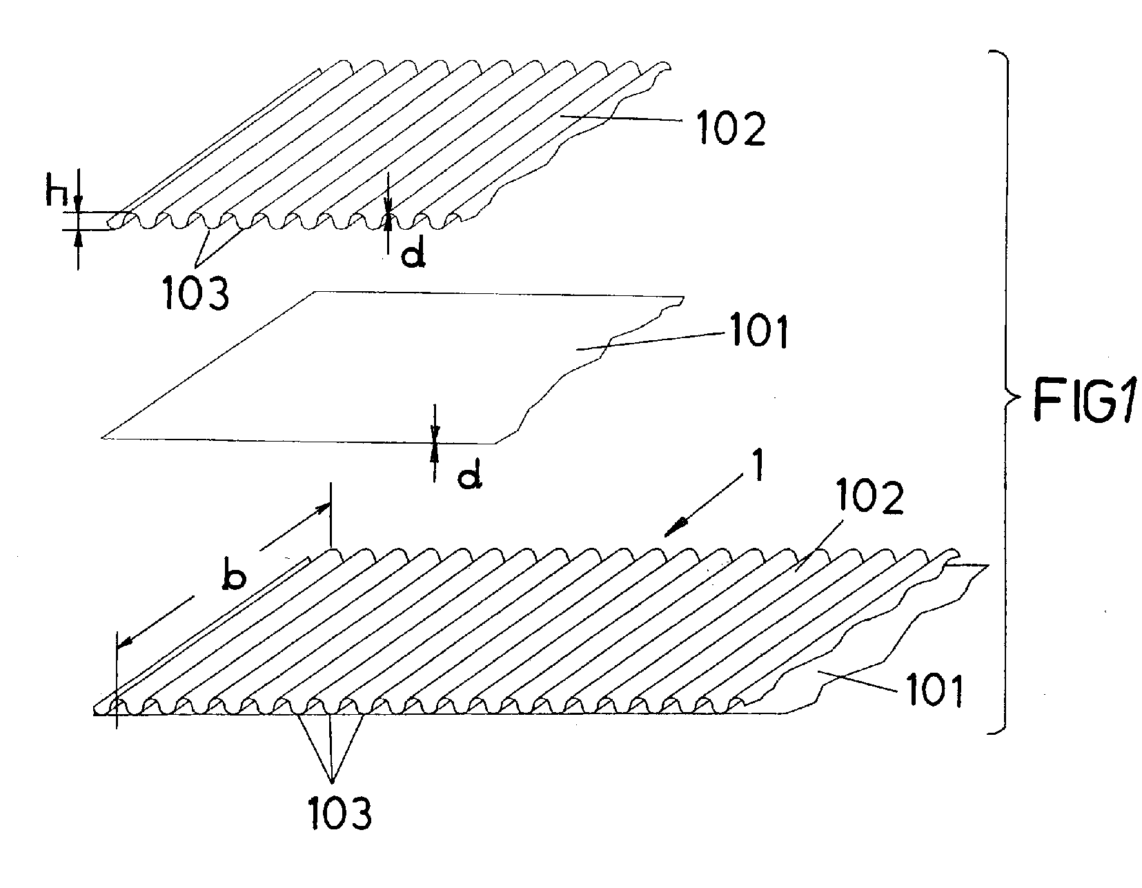
- a honeycomb lamella 1 consists of two transparent Foil webs, a flat film web, the carrier film 101, and one in the longitudinal direction of the web corrugated film web, the honeycomb film 102, the one another in the area of are connected to the carrier film side protruding shaft apex 103.
- This connection can be done by gluing, welding or lamination and each linear over the entire length of the vertex or only in certain areas or point-like along the Extend apex line.
- the film webs are made of a polymer and have a thickness d of max. 100 microns, the wave height h of the honeycomb film 102 max. 10 mm and the width b of the film webs max. approx. 100 mm.
- Honeycomb lamella offers optimized properties with regard to thermal insulation and radiation permeability and is therefore ideal for use with transparent thermal insulation suitable.
- the actual waveform of the honeycomb film 102 is for this optimization is of minor importance, it can therefore be viewed from other points of view, e.g. B. can be selected according to mechanical properties, as long as Volume fraction of the materials, that is, the carrier and honeycomb film 101, 102 of the total volume the honeycomb lamella 1 max. 6% by volume.
- the honeycomb lamella 2 consists of a flat carrier film 201 and a film web 202 corrugated in the longitudinal direction of the web, an additional, in. on the side of the carrier film 201 facing away from the honeycomb film Web longitudinal direction corrugated additional film 203 is attached, which provides greater rigidity arises, but the honeycomb film 2 remains windable.
- the honeycomb lamella 3 also includes Carrier film 301 and to the honeycomb film 302 corrugated in the longitudinal direction of the web, one in the transverse direction of the web corrugated additional film 303, so that the corrugations of the honeycomb film and the Additional foil is perpendicular to each other and a rigid and stackable honeycomb lamella 3 arises.
- insulating bodies can be made from the honeycomb lamellae 6, 7, 8, 9 manufacture with transparent thermal insulation, be it for building facades or with process collectors, can be used.
- 6 is the insulating body 6 made up of individual pieces 601 of the honeycomb lamellae, which are stacked vertically one above the other
- FIG. 7 is the insulating body 7 also from vertically stacked pieces 701 of honeycomb lamellae piled up, although the individual pieces 701 by one wavelength are mutually offset
- the insulating body 8 is made of layers Honeycomb lamella pieces 801 put together, against each other are arranged offset broadly and a substantially oblique front and Form the back.
- the insulating body 9 according to FIG. 9, however, consists of a bale, which is formed by winding a honeycomb lamella web 901 accordingly.
- an insulating body 10 which consists of individual pieces the honeycomb lamella 4 is stacked, which honeycomb lamellae 4 on the front have projecting edge strips 403, these edge strips 403 in FIG the plane of the carrier films 401 and incident rays into the insulating body reflect into it, in FIG. 11, on the other hand, are angled downwards and thus by a reflecting the rays outwards form shading. It is therefore possible To produce insulation with integrated shading device, the Edge strips 403 for operating the shading device without difficulty have swivel adjustment by means of cord pulls or the like.
Landscapes
- Engineering & Computer Science (AREA)
- Physics & Mathematics (AREA)
- Life Sciences & Earth Sciences (AREA)
- Sustainable Development (AREA)
- Sustainable Energy (AREA)
- Thermal Sciences (AREA)
- Chemical & Material Sciences (AREA)
- Combustion & Propulsion (AREA)
- Mechanical Engineering (AREA)
- General Engineering & Computer Science (AREA)
- Laminated Bodies (AREA)
- Panels For Use In Building Construction (AREA)
Abstract
Eine Wabenlamelle (1) für eine transparente Värmedämmung besteht aus zwei durch
eine Wellung wabenbildenden transparenten Folienbahnen (101, 102). Um eine hinsichtlich
der Värmedämmeigenschaflen und hinsichtlich der Strahlungsdurchlässigkeit
optimierbare Wabenlamelle zu schaffen, sind eine flache Folienbahn, die Trägerfolie
(101), und eine in Bahnlängsrichtung gewellte Folienbahn, die Wabenfolie (102), einander
zugeordnet und miteinander im Bereich der trägerfolienseitig vorragenden Wellenscheitel
(103) miteinander verbunden.
Description
Die Erfindung bezieht sich auf eine Wabenlamelle für eine transparente Wärmedämmung aus wenigstens zwei durch eine Wellung wabenbildenden transparenten Folienbahnen.The invention relates to a honeycomb lamella for transparent thermal insulation from at least two transparent film webs forming a honeycomb.
Bei einer transparenten Wärmedämmung können auf Grund der Verwendung transparenter Wärmedämmaterialien auftretende Wärmeverluste durch Solarenergie aufgehoben und darüber hinaus sogar Wärmegewinne für Heizzwecke, insbesondere für eine Gebäudeheizung genutzt werden. Die Wärmedämmaterialien für solche transparente Wärmedämmungen müssen daher im Gegensatz zu den üblichen opaken Dämmstoffen neben der hohen Wärmedämmwirkung eine hohe Durchlässigkeit für Solarstrahlung aufweisen, was eine Optimierung der eingesetzten Dämmaterialien hinsichtlich der energetisch bedeutenden Eigenschaften Wärmeleitung, -konvektion und -strahlung und Strahlungsdurchlässigkeit verlangt. Es sind daher nicht nur geeignete Werkstoffe zu wählen, sondern auch entsprechende Strukturen für die Dämmaterialien unter Beachtung der vorhandenen Hohlräume, Materialwandstärken, Volumenanteile der Materialien, Transparenzeigenschaften, Oberflächenqualitäten und Bearbeitungsgüte u. dgl. vorzugeben.With a transparent thermal insulation can be transparent due to the use Thermal insulation occurring heat losses canceled by solar energy and even heat gains for heating purposes, especially for one Building heating can be used. The thermal insulation materials for such transparent In contrast to the usual opaque insulation materials, thermal insulation must be used in addition to the high thermal insulation effect, a high permeability for solar radiation have what an optimization of the insulation materials used in terms of energetically important properties heat conduction, convection and radiation and Radiation permeability is required. It is therefore not only suitable materials choose, but also appropriate structures for the insulation materials under consideration the existing cavities, material wall thicknesses, volume fractions of the materials, Transparency properties, surface qualities and processing quality u. the like to specify.
Die bekannten Dämmaterialien bestehen meist aus extrudierten Wabenkörpern, die sich aus einer Vielzahl im Querschnitt runder oder polygonaler Röhrchen zusammensetzen, welche Wabenkörper extrusionsbedingt im Vergleich zu Folien eine schlechte Oberflächenqualität und damit ein die Durchlässigkeit beeinträchtigendes Streu- und Reflexionsverhalten mit sich bringen. Ein Beschneiden der Wabenkörper verlangt das Schneiden der vorhandenen kammerstruktur und ergibt ungünstige optische Eigen-schaften in den Schnittbereichen. Außerdem ist auf Grund der Extrusionstechnik die Herstellung von dünnen Wabenwänden nur mit großem apparativem Aufwand möglich, die Wabenkörper sind extrusionsbedingt in Aufbau und Struktur kaum variabel und sie können quer zur Extrusionsrichtung lediglich in recht beschränkten Dimensionen hergestellt werden, wodurch die Fertigung und auch die Verlegung größerer Flächeneinheiten solcher Wabenkörper erschwert werden.The well-known insulating materials mostly consist of extruded honeycomb bodies, which are assemble from a multitude of round or polygonal tubes, which honeycomb bodies have a poor surface quality compared to foils due to extrusion and thus a scattering and reflection behavior that impairs permeability entail. Pruning the honeycomb body requires this Cutting the existing chamber structure and results in unfavorable optical properties in the cutting areas. In addition, due to the extrusion technology The production of thin honeycomb walls is only possible with a lot of equipment, the structure and structure of the honeycomb bodies are hardly variable due to extrusion and they can only be made in very limited dimensions across the direction of extrusion be, whereby the production and also the laying of larger surface units such honeycomb bodies are difficult.
Zur Wärmedämmung von Dachfenstern u. dgl. gibt es auch schon Wabenlamellen aus transparenten und gewellten Folienbahnen, die paarweise mit sich kreuzendem Wellenverlauf verbunden sind. Es entsteht zwar ein transparentes Wärmedämmaterial, doch ergeben die sich kreuzenden Wellen ineinanderübergehende Waben und ungünstige Reflexionsverhältnisse, so daß sich diese Wabenlamellen wegen der schlechten Dämm- und Transparenzeigenschaften nicht für den Einsatz bei transparenten Wärmedämmungen eignen. Dazu kommt noch, daß diese Wabenlamellen durch die Wellenstruktur biegesteif sind und dennoch nur geringe Festigkeitseigenschaften besitzen und sich praktisch nur als Isolierplatten einsetzen lassen.For thermal insulation of roof windows u. The like there are already honeycomb lamellae transparent and corrugated sheeting, in pairs with crossing waves are connected. Although a transparent thermal insulation material is created, it does the intersecting waves result in merging honeycombs and unfavorable Reflection conditions, so that these honeycomb lamellae because of the bad Insulation and transparency properties not for use with transparent thermal insulation own. In addition, these honeycomb lamellae are created by the wave structure are rigid and yet have only low strength properties and can practically only be used as insulation panels.
Der Erfindung liegt daher die Aufgabe zugrunde, eine Wabenlamelle der eingangs geschilderten Art zu schaffen, die rationell herstellbar ist, sich vielfältig einsetzen und auf unterschiedliche Weise verlegen läßt und vor allem hinsichtlich der Wärmedämmung und der Strahlungsdurchlässigkeit höchsten Anforderungen genügt.The invention is therefore based on the object, a honeycomb lamella at the beginning to create described type, which can be produced efficiently, can be used in a variety of ways and can be laid in different ways and especially with regard to thermal insulation and the radiation permeability meets the highest requirements.
Die Erfindung löst diese Aufgabe dadurch, daß eine flache Folienbahn, die Trägerfolie, und eine in Bahnlängsrichtung gewellte Folienbahn, die Wabenfolie, einander zugeordnet und miteinander im Bereich der trägerfolienseitig vorragenden Wellenscheitel verbunden sind. Folienbahnen lassen sich mit gewünschter Oberflächenqualität und Dicke wirtschaftlich herstellen und mit einwandfreien Schnittkanten beschneiden, wobei flache wie in Längsrichtung gewellte Folienbahnen endlos gefertigt und miteinander einfach durch Kleben, Schweißen oder Kaschieren verbunden werden können, wobei die Verbindungsstellen über die ganze Bahnbreite durchgehen oder auch nur punktuell oder bereichsweise gesetzt sein können. Trotz der rationellen Herstellung lassen sich die entstehenden Wabenlamellen in ihrer Dimensionierung und Gestaltung innerhalb weiter Grenzen frei gestalten, was die Anpassung an die unterschiedlichsten Gegebenheiten ermöglicht. Die Wabenlamelle selbst ist auf Grund der Kombination von flacher Trägerfolie und gewellter Wabenfolie in Längsrichtung flexibel und wickelbar, in Querrichtung jedoch ausreichend stabil und knickfest, wobei die einzelnen durch die Wellung entstehenden Waben gegenseitig abgegrenzt sind und bei einem stirnseitigen Abschluß zu isolierenden Luftpolstern führen und die Wärmedämmung beeinträchtigende Strömungserscheinungen verhindern. Die einerseits glatten und anderseits gewellten Wabenlamellen können lageweise übereinandergereiht werden, ohne ein Ineinanderrutschen der Wellungen befürchten zu müssen, und lassen sich zu verschiedensten Dämmkörpern aufbauen.The invention solves this problem in that a flat film web, the carrier film, and a film web corrugated in the longitudinal direction of the web, the honeycomb film, is assigned to one another and connected to one another in the region of the wave apex projecting on the carrier film side are. Foil sheets can be made with the desired surface quality and thickness Produce economically and cut with flawless cut edges, being flat like film webs that are corrugated in the longitudinal direction, made endless and easy with each other can be connected by gluing, welding or laminating, the connection points go through the entire width of the web or only selectively or can be set in areas. Despite the rational production, the emerging honeycomb lamellae in their dimensioning and design within further Design borders freely, which means adapting to the most varied of circumstances enables. The honeycomb lamella itself is due to the combination of flat carrier foil and corrugated honeycomb film flexible and windable in the longitudinal direction, in the transverse direction however sufficiently stable and kink-resistant, the individual due to the corrugation emerging honeycombs are mutually delimited and with a frontal closure lead to insulating air cushions and flow phenomena impairing the thermal insulation prevent. The honeycomb slats, which are smooth on the one hand and corrugated on the other can be lined up in layers without slipping into each other of the curls and have to be feared to various Install insulation bodies.
Es gibt zwar bereits Lächtbaukerne oder Verpackungsmaterialien aus ähnlichen Wäbenstrukturen, doch sind diese bekannten Strukturen aus imprägnierten, papierartigen Materialien hergestellt, was einen Vergleich mit Wabenlamellen für transparente Wärmedämmungen ausschließt.There are already pool structures or packaging materials made of similar honeycomb structures, but these known structures are made of impregnated, paper-like Materials manufactured, which is a comparison with honeycomb slats for transparent thermal insulation excludes.
Besonders günstige Verhältnisse für eine transparente Wärmedämmung ergeben sich dadurch, daß die Folienbahnen eine Dicke (d) von maximal 100 um, vorzugsweise von 25 bis 75 µm, aufweisen, die Wabenfolie eine Wellenhöhe (h) von ca. 10 mm, vorzugsweise 2 bis 7 mm, aufweist, die Breite (b) der Folienbahnen ca. 100 mm beträgt und daß der Volumenanteil der Träger- und Wabenfolie am Gesamtvolumen der Lamelle maximal 6 Vol. % beträgt. Dabei spielt es kaum eine Rolle, welche Wellenform die Wabenfolie besitzt, es können sinusförmige, kammförmige, zickzackförmige Wellenformen od. dgl. sein, wesentlich ist nur die Wellenhöhe und der Volumenanteil der Folienbahnen. Unter Einhaltung solcher Grenzwerte werden ein Wärmedurchlaßkoeffizient λ von 0,7 bis 1,1 W/m2K für die Wärmedämmwirkung und ein Gesamtenergiedurchlaßgrad g von 0,5 bis 0,7 für die Durchlässigkeit von Solarstrahlung erreicht, wenn mit zwei Abdeckscheiben aus 4 mm dickem eisenarmen Glas und einer Folienbreite von 100 mm gemessen wird.Particularly favorable conditions for transparent thermal insulation result from the fact that the film webs have a thickness (d) of at most 100 μm, preferably from 25 to 75 μm, and the honeycomb film has a corrugation height (h) of approximately 10 mm, preferably 2 to 7 mm, the width (b) of the film webs is approximately 100 mm and that the volume fraction of the carrier and honeycomb film in the total volume of the lamella is a maximum of 6% by volume. It does not matter which waveform the honeycomb film has, it can be sinusoidal, comb-shaped, zigzag-shaped waveforms or the like. What is important is only the wave height and the volume fraction of the film webs. In compliance with such limit values, a thermal transmittance coefficient λ of 0.7 to 1.1 W / m 2 K for the thermal insulation effect and a total energy transmittance g of 0.5 to 0.7 for the permeability of solar radiation are achieved when using two 4 mm cover plates thick iron glass and a film width of 100 mm is measured.
Grundsätzlich können für die Folienherstellung alle transparenten und entsprechend temperaturgeeigneten Polymere herangezogen werden, wobei sich aus den amorphen Polymeren für den Niedrigtemperaturbereich CTA (Cellulosetriacetat), CA (Celluloseacetat), PC (Polycarbonat), PMMA (Polymethymetmethacrylat) und für den Hochtemperaturbereich PSU (Polysulfon), PC-HT (Polycarbonat), PES (Polyethersulfon) und PAS (Polyarylsulfon) eignen und von den teilkristallinen Polymeren für den Niedrigtemperaturbereich PET (Polyethylenterephtalat), PP (Polypropylen), COC (Cycloolefinische Copo) sowie für den Hochtemperaturbereich PFA (Perfluor-Alkoxialkan), FEP (Tetrafluorethylen-Hexafluorpropylen), ETFE (Ethylen-Tretrafluorethylen) und PEEK (Polyetheretherketon). Der Niedrigtemperaturbereich umfaßt vor allem die transparente Wärmedämmung für Hausfassaden zur Raumheizung, der Hochtemperaturbereich hingegen zielt beispielsweise auf Prozeßkollektoren u. dgl. ab.Basically, all transparent and corresponding can be used for film production temperature-suitable polymers are used, whereby the amorphous Low-temperature polymers CTA (cellulose triacetate), CA (cellulose acetate), PC (polycarbonate), PMMA (polymethymethacrylate) and for the high temperature range PSU (polysulfone), PC-HT (polycarbonate), PES (polyether sulfone) and PAS (polyarylsulfone) are suitable and of the semi-crystalline polymers for the low temperature range PET (polyethylene terephthalate), PP (polypropylene), COC (cycloolefinic Copo) and for the high temperature range PFA (perfluoro-alkoxyalkane), FEP (tetrafluoroethylene-hexafluoropropylene), ETFE (ethylene tretrafluoroethylene) and PEEK (polyether ether ketone). The low temperature range primarily includes transparent thermal insulation for house facades for space heating, the high temperature area, however targets for example process collectors u. Like.
Trägerfolie und Wabenfolie können durchaus auch aus unterschiedlichen Werkstoffen bestehen, wodurch ein maßgeschneidertes Anwendungsprofil bzw. auch ein maßgeschneidertes Eigenschaftsprofil erreichbar sind.Carrier film and honeycomb film can also be made of different materials exist, whereby a tailor-made application profile or a tailor-made Property profile can be reached.
Nach einer besonders vorteilhaften Ausgestaltung der Erfindung sind Trägerfolie und Wabenfolie gegeneinander breitseits versetzt angeordnet und/oder weisen unterschiedliche Breite auf, so daß zumindest eine der Folien an einer Seite einen überstehenden Randstreifen bildet. Dadurch läßt sich beispielsweise bei einem Anstehen am zugeordneten Absorber der Wärmetransport über die Folien wesentlich reduzieren und außerdem können die Randstreifen zusätzliche funktionelle Aufgaben übernehmen, wodurch die Eigenschaften, aber auch das Aussehen der Wärmedämmung beeinflußt werden können.According to a particularly advantageous embodiment of the invention, carrier film and The honeycomb film is broadly offset from one another and / or have different ones Spread out so that at least one of the foils protrudes on one side Edge strips forms. This allows, for example, a queue on the assigned Absorbers significantly reduce the heat transport via the foils and also the edge strips can take on additional functional tasks, whereby the properties, but also the appearance of the thermal insulation are influenced can.
Sind die vorstehenden Randstreifen beschichtet und/oder strukturiert, können sie zur architektonischen Gestaltung der Wärmedämmfläche in optischer Hinsicht beitragen und bieten die Möglichkeit zur Beeinflussung des Energietransportes durch Reflexion u. dgl., wobei unter Beschichten alle bekannten Verfahren, wie Bedampfen, Farbgebungen, Kaschierungen u. dgl., verstanden wird.If the above edge strips are coated and / or structured, they can be used for Architectural design of the thermal insulation surface contribute visually and offer the possibility to influence the energy transport through reflection u. Like., With coating all known methods, such as vapor deposition, coloring, Laminations and Like., is understood.
Ist der gegenüber der Wabenfolie vorstehende Randstreifen der Trägerfolie filmscharnierartig abwinkelbar, werden diese Randstreifen durch die Wabenfolie statisch abgestützt und lassen sich daher in Längsrichtung schwenkverstellen, wodurch eine gezielte Beeinflussung des Reflexions- und Streuverhaltens und damit des Energieeintrages und der Abstrahlverluste der Wärmedämmung möglich ist. Solche beweglichen Randstreifen lassen sich dann auch als integrierte Beschattungseinrichtung nützen, wodurch Überhitzungen während der Zeiten hoher Energieeinstrahlung bzw. Abstrahlverluste u. dgl. unterbunden werden können. Die Schwenkverstellung der Randstreifen erfordert auf Grund der kleinen Verstellwege und der geringen Verstellkräfte keinen besonderen Konstruktionsaufwand und läßt sich beispielsweise durch Lochungen der Randstreifen und geeignete Schnur- oder Hebelsysteme od. dgl. durchführen. Ein solches Beschattungssystem kann die bisher üblichen zusätzlichen Rollosysteme oder thermotrope Schichtgläser u. dgl. auf rationelle Weise ersetzen.Is the edge strip of the carrier film protruding from the honeycomb film like a film hinge bendable, these edge strips are statically supported by the honeycomb film and can therefore be swiveled in the longitudinal direction, creating a targeted Influencing the reflection and scattering behavior and thus the energy input and the radiation losses of the thermal insulation is possible. Such moving edge strips can then also be used as an integrated shading device, causing overheating during times of high energy radiation or radiation losses u. the like can be prevented. The swivel adjustment of the edge strips requires Because of the small adjustment paths and the low adjustment forces, not a special one Construction effort and can, for example, by perforating the edge strips and carry out suitable cord or lever systems or the like. Such a shading system can be the usual additional blind systems or thermotropic Laminated glasses and Replace the like in a rational manner.
Eine weitere Möglichkeit der Anpassung ergibt sich, wenn mit der Trägerfolie an der wabenfolienabgewandten Seite eine zusätzliche, in Bahnlängs- oder -querrichtung gewellte Folienbahn, eine Zusatzwabenfolie, verbunden ist, womit sich sowohl die Dämmwie die Durchlaßeigenschaften und Festigkeitseigenschaften verändern lassen.Another possibility of adaptation arises if the carrier film is attached to the side facing away from the honeycomb film, an additional one corrugated in the longitudinal or transverse direction of the web Foil sheet, an additional honeycomb film, is connected, with which both the insulation as let the passage properties and strength properties change.
Die Wabenlamelle kann auf verschiedenste Weise eingesetzt werden, wobei beispielsweise in Stücke abgelängte Wabenlamellen zu einem Dämmkörper übereinandergeschichtet sind, was im wesentlichen meist prismatische Wabenkörper ergibt, die durch Schweißen, Kleben, Heften, aber auch einfach durch ein Zusammenbinden oder Umreifen od. dgl. zusammenhalten und als Einheit versetzt werden können.The honeycomb lamella can be used in many different ways, for example Honeycomb slats cut to length are stacked to form an insulating body are what essentially results in prismatic honeycomb bodies, which by Welding, gluing, stapling, but also simply by binding or strapping or the like. Hold together and can be moved as a unit.
Um dabei die Form des Dämmkörpers an unterschiedliche Gegebenheiten anzupassen, können die Wabenlamellenstücke gegeneinander breitseits versetzt geschichtet sein, wodurch sich die Neigung der Vorder- und Hinterseite des Dämmkörpers bezüglich der Wabenlängsrichtung weitgehend frei wählen läßt.In order to adapt the shape of the insulation body to different circumstances, the honeycomb lamella pieces can be layered broadly offset with respect to one another, whereby the inclination of the front and back of the insulation body with respect to the Longitudinal honeycomb direction can be freely chosen.
Eine andere Möglichkeit des Dämmkörperaufbaues besteht darin, daß die Wabenlamellenbahn zu einem Dämmkörper gewickelt ist, so daß ein Wickelballen entsteht, der sich ohne Schwierigkeiten prismatisch verformen und z. B. zur Halterung in Rahmenelemente einsetzen läßt.Another possibility of the insulation body structure is that the honeycomb lamella is wound into an insulating body, so that a wrapping bale is formed deform prismatically without difficulty and z. B. for mounting in frame elements can be used.
In der Zeichnung ist der Erfindungsgegenstand schematisch veranschaulicht, und zwar zeigen
- Fig. 1 bis 5
- fünf verschiedene Ausführungsbeispiele einer erfindungsgemäßen Wabenlamelle jeweils im Schaubild und die
- Fig. 6 bis 11
- sechs Ausführungsbeispiele eines aus einer erfindungsgemäßen Wabenlamelle hergestellten Dämmkörpers ebenfalls jeweils im Schaubild.
- 1 to 5
- five different embodiments of a honeycomb lamella according to the invention each in the diagram and the
- 6 to 11
- six exemplary embodiments of an insulating body produced from a honeycomb lamella according to the invention are also shown in the diagram.
Gemäß Fig. 1 besteht eine erfindungsgemäße Wabenlamelle 1 aus zwei transparenten
Folienbahnen, einer flachen Folienbahn, die Trägerfolie 101, und einer in Bahnlängsrichtung
gewellten Folienbahn, die Wabenfolie 102, die miteinander im Bereich der
trägerfolienseitig vorragenden Wellenscheitel 103 verbunden sind. Diese Verbindung
kann durch Kleben, Schweißen oder Kaschieren erfolgen und sich jeweils linienförmig
über die gesamte Scheitellänge oder nur bereichsweise oder punktförmige entlang der
Scheitellinie erstrecken. Die Folienbahnen bestehen aus einem Polymer und weisen
eine Dicke d von max. 100 µm auf, wobei die Wellenhöhe h der Wabenfolie 102 max.
10 mm und die Breite b der Folienbahnen max. ca. 100 mm betragen. Eine solche
Wabenlamelle bietet optimierte Eigenschaften hinsichtlich Wärmedämmung und Strahlungsdurchlässigkeit
und ist daher bestens für den Einsatz bei transparenten Wärmedämmungen
geeignet. Dabei ist die eigentliche Wellenform der Wabenfolie 102 für
diese Optimierung von untergeordneter Bedeutung, sie kann daher nach anderen Gesichtspunkten,
z. B. nach mechanischen Eigenschaften gewählt werden, so lange der
Volumenanteil der Materialien, also der Träger- und Wabenfolie 101, 102 am Gesamtvolumen
der Wabenlamelle 1 max. 6 Vol. % ausmacht.1, a
Gemäß dem Ausführungsbeispiel nach Fig. 2 besteht die Wabenlamelle 2 aus einer
flachen Trägerfolie 201 und einer in Bahnlängsrichtung gewellten Folienbahn 202,
wobei an der wabenfolienabgewandten Seite der Trägerfolie 201 eine zusätzliche, in
Bahnlängsrichtung gewellte Zusatzfolie 203 befestigt ist, wodurch eine höhere Steifigkeit
entsteht, aber die Wabenfolie 2 wickelbar bleibt.2, the
Gemäß dem Ausführungsbeispiel nach Fig. 3 umfaßt die Wabenlamelle 3 zusätzlich zur
Trägerfolie 301 und zur in Bahnlängsrichtung gewellten Wabenfolie 302 eine in Bahnquerrichtung
gewellte Zusatzfolie 303, so daß die Wellungen der Wabenfolie und der
Zusatzfolie zueinander senkrecht verlaufen und eine biegesteife und stapelbare Wabenlamelle
3 entsteht.According to the embodiment of FIG. 3, the
Wie in Fig. 4 und 5 angedeutet, ist es möglich, die Wabenlamellen 4, 5 aus unterschiedlich
breiten Trägerfolien 401, 501 und Wabenfolien 402, 502 zusammenzusetzen,
so daß einseitig oder, wie dargestellt, beidseitig der Wabenlamelle 4, 5 ein vorstehender
Randstreifen 403, 503 verbleibt, welche Randstreifen speziell beschichtet, bedampft,
kaschiert oder strukturiert sein können und sowohl zur architektonischen Gestaltung
dienen als auch funktionelle Aufgaben, wie Beeinflussung des Energietransportes,
übernehmen können, wobei die Randstreifen 403 der flachen Trägerfolie auch
entlang der Wabenfolieränder abwinkelbar sind.As indicated in FIGS. 4 and 5, it is possible to make the
Wie in den Fig. 6 bis 9 angedeutet, lassen sich aus den Wabenlamellen Dämmkörper
6, 7, 8, 9 fertigen, die bei einer transparenten Wärmedämmung, sei es bei Gebäudefassaden
oder bei Prozeßkollektoren, einsetzbar sind. Gemäß Fig. 6 ist der Dämmkörper
6 aus einzelnen plattenförmig abgelängten Stücken 601 der Wabenlamellen aufgebaut,
die senkrecht übereinandergeschichtet werden, gemäß Fig. 7 ist der Dämmkörper
7 ebenfalls aus senkrecht übereinandergeschichteten Stücken 701 von Wabenlamellen
aufgeschichtet, wobei allerdings die einzelnen Stücke 701 um eine Wellenlänge
gegeneinander versetzt sind, und gemäß Fig. 8 ist der Dämmkörper 8 aus übereinandergeschichteten
Wabenlamellenstücken 801 zusammengesetzt, die gegeneinander
breitseits versetzt angeordnet sind und eine im wesentlichen schräge Vorder- und
Rückseite bilden. Der Dämmkörper 9 gemäß Fig. 9 besteht hingegen aus einem Ballen,
der durch entsprechendes Wickeln einer Wabenlamellenbahn 901 entsteht.As indicated in FIGS. 6 to 9, insulating bodies can be made from the
In Fig. 10 und 11 ist ein Dämmkörper 10 veranschaulicht, der aus einzelnen Stücken
der Wabenlamelle 4 aufgeschichtet ist, welche Wabenlamellen 4 an der Vorderseite
überstehende Randstreifen 403 aufweisen, wobei in Fig. 10 diese Randstreifen 403 in
der Ebene der Trägerfolien 401 verlaufen und einfallende Strahlen in den Dämmkörper
hineinreflektieren, in Fig. 11 hingegen abwärts abgewinkelt sind und damit durch ein
auswärts Reflektieren der Strahlen eine Verschattung bilden. Es ist daher möglich,
Dämmkörper mit integrierter Verschattungseinrichtung herzustellen, wobei sich die
Randstreifen 403 zur Betätigung der Verschattungseinrichtung ohne Schwierigkeiten
mittels Schnurzügen od. dgl. schwenkverstellen lassen.10 and 11, an
Claims (14)
Applications Claiming Priority (3)
| Application Number | Priority Date | Filing Date | Title |
|---|---|---|---|
| AT203297 | 1997-12-01 | ||
| AT0203297A AT407974B (en) | 1997-12-01 | 1997-12-01 | TRANSPARENT THERMAL INSULATION WITH HONEYCOMB BLADES |
| AT2032/97 | 1997-12-01 |
Publications (2)
| Publication Number | Publication Date |
|---|---|
| EP0919779A2 true EP0919779A2 (en) | 1999-06-02 |
| EP0919779A3 EP0919779A3 (en) | 2000-06-07 |
Family
ID=3526346
Family Applications (1)
| Application Number | Title | Priority Date | Filing Date |
|---|---|---|---|
| EP98890351A Withdrawn EP0919779A3 (en) | 1997-12-01 | 1998-11-30 | Lamellar honeycomb for transparent insulation |
Country Status (2)
| Country | Link |
|---|---|
| EP (1) | EP0919779A3 (en) |
| AT (1) | AT407974B (en) |
Family Cites Families (13)
| Publication number | Priority date | Publication date | Assignee | Title |
|---|---|---|---|---|
| AT329828B (en) * | 1974-06-17 | 1976-05-25 | Peter M Schmid | LIGHT TRANSLUCENT COMPONENT |
| AU8342575A (en) * | 1974-08-06 | 1977-02-03 | Philberth K | Solar heaters |
| IT1070617B (en) * | 1976-07-20 | 1985-04-02 | Fiat Spa | LOW COST SOLAR PANEL |
| DE2640754A1 (en) * | 1976-09-10 | 1978-03-16 | Karlheinz Dr Rer Nat Raetz | Solar energy collector for hot water system - of plastic cellular construction with protection against frost and over temperature |
| JPS56144354A (en) * | 1980-04-09 | 1981-11-10 | Toshio Nishino | Water heater utilizing solar heat |
| US4409274A (en) * | 1982-02-24 | 1983-10-11 | Westvaco Corporation | Composite material |
| DE3406952A1 (en) * | 1984-02-25 | 1985-10-24 | Basf Ag, 6700 Ludwigshafen | METHOD FOR PRODUCING THREE-DIMENSIONAL LIGHT-TRANSPARENT HONEYCOMB STRUCTURES FROM PLASTICS |
| GB8423522D0 (en) * | 1984-09-20 | 1984-10-24 | Kiltmaine Ltd | Light transmitting insulating panel |
| JPS61180843A (en) * | 1985-01-31 | 1986-08-13 | Mitsubishi Electric Corp | Humidifier |
| CH676267A5 (en) * | 1986-01-29 | 1990-12-28 | Rolf W Dr Peter | Translucent heat-insulating plate - comprises stack of sheets embossed to form supporting distance-pieces |
| US4897146A (en) * | 1988-01-28 | 1990-01-30 | General Electric Company | Apparatus and method for fabricating structural panels having corrugated core structures and panel formed therewith |
| US5009054A (en) * | 1989-09-08 | 1991-04-23 | Anthony E. Braun | Method of storing thread in an embroidery thread-holder |
| DE19611475A1 (en) * | 1996-03-22 | 1997-09-25 | Wimmer Ulrich Dipl Ing Fh | Heat-insulating foil with air bubbles |
-
1997
- 1997-12-01 AT AT0203297A patent/AT407974B/en not_active IP Right Cessation
-
1998
- 1998-11-30 EP EP98890351A patent/EP0919779A3/en not_active Withdrawn
Also Published As
| Publication number | Publication date |
|---|---|
| EP0919779A3 (en) | 2000-06-07 |
| ATA203297A (en) | 2000-12-15 |
| AT407974B (en) | 2001-07-25 |
Similar Documents
| Publication | Publication Date | Title |
|---|---|---|
| EP1181421B1 (en) | Lightweight construction element in the form of a hollow body contoured honeycomb structure | |
| DE19514019C2 (en) | Roller blind film and manufacturing process | |
| DE2617577A1 (en) | COVER | |
| EP2041388B1 (en) | Sun protection device with angle-selective transmission properties | |
| DE3230639C2 (en) | ||
| DE2758041C2 (en) | Use of a component consisting of at least two films, in particular plastic films, arranged one above the other | |
| DE2840023A1 (en) | Collapsible sunblind or flexible thermal insulation structure - made of honeycomb elements convertible to flat structures | |
| DE69208641T2 (en) | Plate-shaped element made of synthetic resin | |
| DE2835371C2 (en) | Solar collector | |
| DE19622670C2 (en) | Light deflection plate with two flat elements | |
| EP0919779A2 (en) | Lamellar honeycomb for transparent insulation | |
| DE19736768A1 (en) | Thermally insulating transparent construction member | |
| BE1020836A5 (en) | FOLDABLE HEATER. | |
| DE69410789T2 (en) | HEAT RAYS REFLECTIVE AND / OR ABSORBENT MATERIAL | |
| EP0030246B1 (en) | Translucent heat-insulating composite unit | |
| DE1784524C3 (en) | Sound absorbing and warm insulating composite material | |
| EP1831614A1 (en) | Radiation collector | |
| EP0083595B1 (en) | Thermal insulation curtain for windows, doors and the like | |
| DE4412865A1 (en) | Lightweight construction member | |
| DE60313318T2 (en) | Extruded honeycomb panel | |
| EP0049418B1 (en) | Partially transparent blind formed with two different surfaces | |
| EP0358920A1 (en) | Roller shutters | |
| DE69908669T2 (en) | Extruded multi-wall sheet made of materials with different optical and mechanical properties | |
| EP0708211B1 (en) | Multilayer cross-braced layer | |
| EP2103759A1 (en) | Forming board |
Legal Events
| Date | Code | Title | Description |
|---|---|---|---|
| PUAI | Public reference made under article 153(3) epc to a published international application that has entered the european phase |
Free format text: ORIGINAL CODE: 0009012 |
|
| AK | Designated contracting states |
Kind code of ref document: A2 Designated state(s): AT CH DE ES FR GB LI NL |
|
| AX | Request for extension of the european patent |
Free format text: AL;LT;LV;MK;RO;SI |
|
| PUAL | Search report despatched |
Free format text: ORIGINAL CODE: 0009013 |
|
| AK | Designated contracting states |
Kind code of ref document: A3 Designated state(s): AT BE CH CY DE DK ES FI FR GB GR IE IT LI LU MC NL PT SE |
|
| AX | Request for extension of the european patent |
Free format text: AL;LT;LV;MK;RO;SI |
|
| 17P | Request for examination filed |
Effective date: 20001205 |
|
| AKX | Designation fees paid |
Free format text: AT CH DE ES FR GB LI NL |
|
| 17Q | First examination report despatched |
Effective date: 20021118 |
|
| STAA | Information on the status of an ep patent application or granted ep patent |
Free format text: STATUS: THE APPLICATION IS DEEMED TO BE WITHDRAWN |
|
| 18D | Application deemed to be withdrawn |
Effective date: 20030701 |