EP0919776B1 - Hinge device, particularly for the door of household electric appliances and the like with counterbalancing and self-regulating means - Google Patents
Hinge device, particularly for the door of household electric appliances and the like with counterbalancing and self-regulating means Download PDFInfo
- Publication number
- EP0919776B1 EP0919776B1 EP98122491A EP98122491A EP0919776B1 EP 0919776 B1 EP0919776 B1 EP 0919776B1 EP 98122491 A EP98122491 A EP 98122491A EP 98122491 A EP98122491 A EP 98122491A EP 0919776 B1 EP0919776 B1 EP 0919776B1
- Authority
- EP
- European Patent Office
- Prior art keywords
- sliding
- door
- frontal wall
- shaped element
- counterbalancing
- Prior art date
- Legal status (The legal status is an assumption and is not a legal conclusion. Google has not performed a legal analysis and makes no representation as to the accuracy of the status listed.)
- Expired - Lifetime
Links
- 230000008878 coupling Effects 0.000 claims description 18
- 238000010168 coupling process Methods 0.000 claims description 18
- 238000005859 coupling reaction Methods 0.000 claims description 18
- 230000003042 antagnostic effect Effects 0.000 claims description 14
- 230000009471 action Effects 0.000 claims description 8
- 230000006835 compression Effects 0.000 claims description 6
- 238000007906 compression Methods 0.000 claims description 6
- 230000000750 progressive effect Effects 0.000 claims description 6
- 238000006243 chemical reaction Methods 0.000 claims description 4
- OKTJSMMVPCPJKN-UHFFFAOYSA-N Carbon Chemical compound [C] OKTJSMMVPCPJKN-UHFFFAOYSA-N 0.000 claims description 2
- 239000004677 Nylon Substances 0.000 claims description 2
- 229910002804 graphite Inorganic materials 0.000 claims description 2
- 239000010439 graphite Substances 0.000 claims description 2
- 229920001778 nylon Polymers 0.000 claims description 2
- 230000003247 decreasing effect Effects 0.000 claims 1
- 230000033001 locomotion Effects 0.000 description 7
- 239000005557 antagonist Substances 0.000 description 6
- 230000033228 biological regulation Effects 0.000 description 3
- 238000009434 installation Methods 0.000 description 3
- 230000008901 benefit Effects 0.000 description 2
- 230000000694 effects Effects 0.000 description 2
- 229910052799 carbon Inorganic materials 0.000 description 1
- 230000003993 interaction Effects 0.000 description 1
- 239000000463 material Substances 0.000 description 1
- 230000007246 mechanism Effects 0.000 description 1
- 230000010355 oscillation Effects 0.000 description 1
- 230000036316 preload Effects 0.000 description 1
- 230000001105 regulatory effect Effects 0.000 description 1
Images


Classifications
-
- F—MECHANICAL ENGINEERING; LIGHTING; HEATING; WEAPONS; BLASTING
- F24—HEATING; RANGES; VENTILATING
- F24C—DOMESTIC STOVES OR RANGES ; DETAILS OF DOMESTIC STOVES OR RANGES, OF GENERAL APPLICATION
- F24C15/00—Details
- F24C15/02—Doors specially adapted for stoves or ranges
- F24C15/023—Mounting of doors, e.g. hinges, counterbalancing
-
- A—HUMAN NECESSITIES
- A47—FURNITURE; DOMESTIC ARTICLES OR APPLIANCES; COFFEE MILLS; SPICE MILLS; SUCTION CLEANERS IN GENERAL
- A47L—DOMESTIC WASHING OR CLEANING; SUCTION CLEANERS IN GENERAL
- A47L15/00—Washing or rinsing machines for crockery or tableware
- A47L15/42—Details
- A47L15/4251—Details of the casing
- A47L15/4257—Details of the loading door
- A47L15/4261—Connections of the door to the casing, e.g. door hinges
-
- E—FIXED CONSTRUCTIONS
- E05—LOCKS; KEYS; WINDOW OR DOOR FITTINGS; SAFES
- E05F—DEVICES FOR MOVING WINGS INTO OPEN OR CLOSED POSITION; CHECKS FOR WINGS; WING FITTINGS NOT OTHERWISE PROVIDED FOR, CONCERNED WITH THE FUNCTIONING OF THE WING
- E05F1/00—Closers or openers for wings, not otherwise provided for in this subclass
- E05F1/08—Closers or openers for wings, not otherwise provided for in this subclass spring-actuated, e.g. for horizontally sliding wings
- E05F1/10—Closers or openers for wings, not otherwise provided for in this subclass spring-actuated, e.g. for horizontally sliding wings for swinging wings, e.g. counterbalance
- E05F1/12—Mechanisms in the shape of hinges or pivots, operated by springs
- E05F1/1246—Mechanisms in the shape of hinges or pivots, operated by springs with a coil spring perpendicular to the pivot axis
- E05F1/1253—Mechanisms in the shape of hinges or pivots, operated by springs with a coil spring perpendicular to the pivot axis with a compression spring
- E05F1/1261—Mechanisms in the shape of hinges or pivots, operated by springs with a coil spring perpendicular to the pivot axis with a compression spring for counterbalancing
-
- E—FIXED CONSTRUCTIONS
- E05—LOCKS; KEYS; WINDOW OR DOOR FITTINGS; SAFES
- E05D—HINGES OR SUSPENSION DEVICES FOR DOORS, WINDOWS OR WINGS
- E05D11/00—Additional features or accessories of hinges
- E05D11/08—Friction devices between relatively-movable hinge parts
-
- E—FIXED CONSTRUCTIONS
- E05—LOCKS; KEYS; WINDOW OR DOOR FITTINGS; SAFES
- E05Y—INDEXING SCHEME ASSOCIATED WITH SUBCLASSES E05D AND E05F, RELATING TO CONSTRUCTION ELEMENTS, ELECTRIC CONTROL, POWER SUPPLY, POWER SIGNAL OR TRANSMISSION, USER INTERFACES, MOUNTING OR COUPLING, DETAILS, ACCESSORIES, AUXILIARY OPERATIONS NOT OTHERWISE PROVIDED FOR, APPLICATION THEREOF
- E05Y2201/00—Constructional elements; Accessories therefor
- E05Y2201/20—Brakes; Disengaging means; Holders; Stops; Valves; Accessories therefor
- E05Y2201/252—Type of friction
- E05Y2201/26—Mechanical friction
-
- E—FIXED CONSTRUCTIONS
- E05—LOCKS; KEYS; WINDOW OR DOOR FITTINGS; SAFES
- E05Y—INDEXING SCHEME ASSOCIATED WITH SUBCLASSES E05D AND E05F, RELATING TO CONSTRUCTION ELEMENTS, ELECTRIC CONTROL, POWER SUPPLY, POWER SIGNAL OR TRANSMISSION, USER INTERFACES, MOUNTING OR COUPLING, DETAILS, ACCESSORIES, AUXILIARY OPERATIONS NOT OTHERWISE PROVIDED FOR, APPLICATION THEREOF
- E05Y2900/00—Application of doors, windows, wings or fittings thereof
- E05Y2900/30—Application of doors, windows, wings or fittings thereof for domestic appliances
- E05Y2900/308—Application of doors, windows, wings or fittings thereof for domestic appliances for ovens
Definitions
- the present invention concerns a hinge device for household electric appliances and the like.
- the object of the invention is a hinge device of the self-regulating type, fit to allow the articulation between the door and the related appliance body, preferably a dishwasher.
- the known hinges such as self-regulating, are fit to produce a counterbalancing action during the opening and closing phases of the door linked thereto. Every hinge is provided with a kinematic motion, moving as regards the hinge movement, including elastic means, tensile or compressive stressed, in such a way that its elastic reaction varies as regards the door position and is fit to balance the weight of the door during its opening.
- Such hinges include a series of lever elements mutually pivoted fit to constitute a mechanism providing the gradually increasing of the reaction strength of the elastic element during the door opening and so counterbalancing the moment produced by the door weight that increases as regards the increasing of the projection from the appliance frame and therefore by increasing the lever arm.
- the main drawback of the known hinges is that to vary the counterbalancing strength exerted by the spring assembled with the appliance it is necessary to replace said spring with another able to produce a suitable counterbalancing strength.
- the known hinges are provided with means fit to allow the adjustment of the counterbalancing force of the elastic means as regards the door weight.
- adjustment means are constituted by small cable that, suitably tensioned through regulation screws accessible from outside of the appliance, allow opportunely to pre-load the spring in such a way to vary its initial elastic reaction.
- the regulation systems of the hinge devices do not always allow a wide adjustment range of the counterbalancing action, therefore the same hinge is not often usable in different appliances having doors of different weights or providing for panels of different weights.
- a hinge device also suitable for the door of household electric appliances and the like, of the type including a coupling element having a frontal wall and fixed to the frame of said hinge device fixable to the frame of a household appliance.
- the device further includes support element, pivoted to said coupling element, through a pivot, and to which said door is fixed; first counterbalancing means, fitted to exert an antagonistic force opposing the weight force of said door.
- Said device includes a shaped element constituted by a superior portion, to which said first counterbalancing means are hinged, by a middle portion and an inferior portion to which said support element is hinged, said shaped element having an outer contour and an inner contour turned toward said support element.
- the device has sliding means interposed between said shaped element and said frontal wall of said coupling element and designed to allow the sliding of said shaped element on said frontal wall so as to cause the progressive increasing of the arm of said antagonistic force in consequence of the passage from a closing condition, in which said support element is faced to said frontal wall, to a condition of extreme opening, in which the axle of said support element is almost orthogonal to said frontal wall.
- the main object of the present invention is to propose a hinge device, fit to allow the articulation between the door and the related appliance body, having a counterbalancing self-balancing and self-regulating system, without adjustment means fit to automatically counterbalance doors of variable weight within a reasonable range
- Another object of the present invention is to propose a device of simple making, easy installation, sure and precise use.
- Said objects are archived according to the claim content.
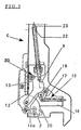
- numeral 1 refers to a hinge device, particularly for the door of electric appliances and the like, including a coupling element 2, a support element 3, first counterbalancing means 6 and a shaped element 9.
- the coupling element 2 is fixed to the frame 10 of the hinge device 1 fixable to the structure, known and not illustrated, of each electric appliance.
- the support element 3 is pivoted to the coupling element 2 through a pivot 5 allowing the rotation.
- a joint plate 4 is fixed near to an end of the support element 3 to which the door, known and not illustrated, is fixed. Moreover, there is an abutment 20 in correspondence of the remaining end of the support element 3.
- the coupling element 2 has a frontal wall 12 interposed between the support element 3 and the shaped element 9.
- the first counterbalancing means 6 are constituted by a spring 22 interposed between the head of a rod 23 and a seat 24 therefrom the free end of the rod 23 protrudes.
- the shaped element 9 has a superior portion 9a hinged to the free end of the rod 23 and an inferior portion 9c hinged to the support element 3 through a pivot 26.
- Such shaped element 9 has middle portion 9b defining an inner contour 7 and an outer contour 8, ppposed to the frontal wall 12.
- the operation of the known hinge device 1 illustrated in the figures 1 and 2 is very simple, because the door opening of the appliance coupled to the support element 3 causes the passage of this latter from a closing condition C, in which the support element 3 is faced to the frontal wall 12 of the coupling element 2, and therefore the door is turned toward the body of the appliance in such a way to close the frontal opening thereof, to an extreme opening condition A, in which the longitudinal axle of the support element 3 is nearly orthogonal to the frontal wall 12, and therefore the door is almost orthogonal with the frontal opening of the appliance.
- the opening condition A is mainly limited by the abutment 20 of the support element 3 that, consequently its rotation, contacts inwardly the frontal wall 12 of the coupling element 2
- the support element 3 rotates on the pivot 5 causing the moving of the shaped element 9.
- the sliding block 13 is forced to slide with friction on the frontal wall 12 exerting thereon a friction resistance force of proportionally increasing intensity as regards the door opening and therefore as regards the passage from the closing condition C to the opening condition A.
- the rod 23 is moved downward causing the subsequent progressive compression of the spring 22,exerting an antagonist force proportionally increasing with the door opening and able to oppose the weight force.
- the combined action of the antagonist force of the first counterbalancing means 6 and the sliding with friction of the sliding block 13 along the frontal wall 12 allows a continuous balancing of the door and of a possible covering panel coupled thereto so allowing the same door to balance in correspondence of each intermediate opening angle reached by the door.
- the contact surface of the sliding block 13 with the frontal wall 12 is constituted by nylon enriched with a percentage of graphite ranging between 5% and 20%, and preferably it is of 12%, so that to increase the sliding friction between the surfaces.
- the self-regulating effect is completely reached with a whole weight of the door and/or panel varying from 6 to 10 kilograms.
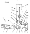
- hinge device 1 object of the present invention is illustrated in figures 3, 4 and includes the use of second counterbalancing means 15.
- Such second counterbalancing means 15 are fixed to the coupling element 2, next to its end opposed to the frontal wall 12, and are active with the outer contour 8 of the shaped element 9.
- These means includes a lever 17 whose oscillation plain is parallel to the moving plane of the shaped element 9.
- An end of the lever 17 is hinged, through a pivot 18, to the coupling element 2 and the remaining end is pivoted to the end of elastic means 19 while the middle portion supports an sliding element 14, directly in contact with the outer contour 8, for instance constituted by a free rolls 14a.
- the elastic means 19 include a guiding rod 19b of a helical spring 19 subjected to compression, whose free end is slidingly supported by a bracket 16 fixed to the frame 10.
- the operation of the hinge device 1, shown in the figures 3 and 4 is identical to the operation of the known hinge device of figures 1 and 2, with the only difference that the second counterbalancing means 15 allow to exert a further antagonistic force on the shaped element 9 proportionally increasing in correspondence of the passage from the closing condition C to the opening condition A of the door.
- the rolls 14a rolls or slides on the outer contour 8, particularly from the middle portion 9b toward the superior portion 9a, causing the rotation of the lever 17 around the pivot 18 and therefore the crushing, that is the compression, of the spring 19a onto the bracket 16 which transmits an equal and contrary force to such stress to the shaped element 9 for interposition of the roll 14a.
- the shaped element 9 is subjected to a further antagonist force opposing the movement thereof during the passage from the closing condition C to the extreme opening condition A and therefore increases the force against the weight force of the door and/or of the optional covering panel applied thereto.
- the self-regulating effect is completely reached for a total weight of the door and/or of the panel varying from 6 to 14 kilograms.
- sliding element 14 can also be constituted by a sliding block 14a which slides or runs on the outer contour 8.
- this hinge device 1 a self-balancing condition of the weight of the door and/or of the panel-door is reached without using any adjustment means of antagonistic force of the counterbalancing means, so making a hinge device completely self-regulating for a wide range of the weight of the door and the door together with the covering panel.
- the antagonistic force of the first counterbalancing means 6 and the further antagonist force of the second counterbalancing means 15 vary proportionally to the opening angle of the door and therefore increase in the passage from the closing C to opening A conditions, and decrease in the inverse passage, however always proportionally respectively to the increase or to the decrease of weight force of the door or of the door with the covering panel.
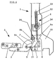
- the figures 5 and 6 illustrate a second embodiment of the known hinge device 1 previously described, in which the inner contour 7 of the shaped element 9 is almost cycloidal and has an abutment 33 near the end of the superior portion 9a, and moreover is slidingly driven by the sliding means 30 constituted by a free roll 11 supported by the coupling element 2, while the outer contour 8 is almost rectilinear.
- the portion of the shaped element 9 included between the middle portion 9b and the second end 9c has a recess 21.
- the operation of the hinge device 1 of this second embodiment is identical to the operation of the first embodiment with the exception that the extreme opening A condition is not only mainly caused by the abutment 20 of the support element 3 that, subsequently its rotation, inwardly contacts the frontal wall 12 of the coupling element 2, but also because the recess 21 of the shaped element 9 is conformed in such a way to lean firmly on the pivot 5 and the abutment 33 is fit to contact the external surface of the roll 11.
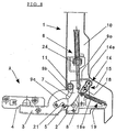
- a variant of the hinge device 1 includes the use of the second counterbalancing means 15 similar to those of the preferred embodiment with the exception that the lever 17 is pivoted to the pivot 18 in its central zone, one of its end is bound to the elastic means 19 while the free end rotatingly supports the free roll 14a.
- the elastic means 19 are constituted by a spring 19a whose ends are fixed respectively to the lever 17 end and to a bracket 16 hook so that the spring 19a works in traction.
- the elastic means 19 can be fixed to the lever 17 between the pivot 18 and the free end of this latter, supporting the sliding element 14, so that the spring 19a of the elastic means 19 works in compression rather than in traction
- the main advantage of the present invention is therefore to furnish a hinge device, designed to allow the articulation between the door and the body of a related appliance, fitted with a counterbalancing system of the self-adjusting and self-balancing type, without adjustment means, able to counterbalance doors of weight varying automatically within a reasonable but wide range.
Landscapes
- Engineering & Computer Science (AREA)
- Chemical & Material Sciences (AREA)
- Combustion & Propulsion (AREA)
- Mechanical Engineering (AREA)
- General Engineering & Computer Science (AREA)
- Closing And Opening Devices For Wings, And Checks For Wings (AREA)
- Hinges (AREA)
- Extensible Doors And Revolving Doors (AREA)
Description
- The present invention concerns a hinge device for household electric appliances and the like.
- In particular the object of the invention is a hinge device of the self-regulating type, fit to allow the articulation between the door and the related appliance body, preferably a dishwasher.
- It is known that the doors of appliances such as ovens, dishwashers and the like, are fixed to the electric household frame through a couple of hinges allowing the door rotation between a closing and an opening positions.
- The known hinges, such as self-regulating, are fit to produce a counterbalancing action during the opening and closing phases of the door linked thereto. Every hinge is provided with a kinematic motion, moving as regards the hinge movement, including elastic means, tensile or compressive stressed, in such a way that its elastic reaction varies as regards the door position and is fit to balance the weight of the door during its opening.
- Such hinges include a series of lever elements mutually pivoted fit to constitute a mechanism providing the gradually increasing of the reaction strength of the elastic element during the door opening and so counterbalancing the moment produced by the door weight that increases as regards the increasing of the projection from the appliance frame and therefore by increasing the lever arm.
- The main drawback of the known hinges is that to vary the counterbalancing strength exerted by the spring assembled with the appliance it is necessary to replace said spring with another able to produce a suitable counterbalancing strength.
- To avoid such drawback, the known hinges are provided with means fit to allow the adjustment of the counterbalancing force of the elastic means as regards the door weight. For instance, such adjustment means are constituted by small cable that, suitably tensioned through regulation screws accessible from outside of the appliance, allow opportunely to pre-load the spring in such a way to vary its initial elastic reaction.
- The need of regulating such counterbalancing strength is particularly evident in the case in which the appliances are integral part of modular furniture, such as for instance modular ranges, which, for aesthetic reasons, include the panel assemblage covering the appliance doors. Every panel weights therefore the related door in a variable way depending on the material thereof, so being a random variable for the makers of the appliances, and particularly of the hinges.
- Another drawback, due to the adjustment of the regulation means, inside the hinge, during the panel assemblage onto the appliance door, is that such manual operation is not often made with workmanlike, for instance because of the non symmetrically adjustment of the counterbalancing action for each hinge. The consequence is that the elastic means of one of the two hinges is more loaded than the other and therefore subjected to greater stresses that can cause the breaking thereof or it can cause a non symmetrical opening or closing of the door with the consequent damage of the appliance functionality.
- Besides, the regulation systems of the hinge devices do not always allow a wide adjustment range of the counterbalancing action, therefore the same hinge is not often usable in different appliances having doors of different weights or providing for panels of different weights.
- Therefore it is often necessary to make the same hinge model with different spring types of the related counterbalancing means, to be used depending on the appliance type. This causes an heavy drawback for the management of each single type of hinge concerning the carrying out of hinges with different springs, the adjustment during the furniture installation and the storage of the same hinge type with different springs.
- Document US-A-4 269 165, which describes all the features of the preamble of
claim 1, discloses a hinge device, also suitable for the door of household electric appliances and the like, of the type including a coupling element having a frontal wall and fixed to the frame of said hinge device fixable to the frame of a household appliance. The device further includes support element, pivoted to said coupling element, through a pivot, and to which said door is fixed; first counterbalancing means, fitted to exert an antagonistic force opposing the weight force of said door. - Said device includes a shaped element constituted by a superior portion, to which said first counterbalancing means are hinged, by a middle portion and an inferior portion to which said support element is hinged, said shaped element having an outer contour and an inner contour turned toward said support element.
- The device has sliding means interposed between said shaped element and said frontal wall of said coupling element and designed to allow the sliding of said shaped element on said frontal wall so as to cause the progressive increasing of the arm of said antagonistic force in consequence of the passage from a closing condition, in which said support element is faced to said frontal wall, to a condition of extreme opening, in which the axle of said support element is almost orthogonal to said frontal wall.
- The main object of the present invention is to propose a hinge device, fit to allow the articulation between the door and the related appliance body, having a counterbalancing self-balancing and self-regulating system, without adjustment means fit to automatically counterbalance doors of variable weight within a reasonable range
- Another object of the present invention is to propose a device of simple making, easy installation, sure and precise use.
- Said objects are archived according to the claim content.
- Enclosed Figures 1, 2, 5 and 6 show a hinge device having a known feature combination.
- The features of the preferred embodiment of the invention are underlined in the enclosed
drawings - Figure 1 shows a side view of a hinge device in a closing condition;
- figure 2 shows a side view the device of figure 1 in correspondence of an extreme opening condition;
- figure 3 shows a side view of the preferred embodiment of the device of the present invention in the closing condition;
- figure 4 shows a side view of the device of figure 3 at the extreme opening condition;
- figure 5 shows a side view of a second embodiment of the device of figure 1 in the closing condition;
- figure 6 shows a side sight of the device of figure 5 in the extreme opening condition;
- figure 7 shows a side sight of a variant of the embodiment of the device of figure 3 in the closing condition;
- figure 8 shows a side view of the device of figure 7 in the extreme opening condition.
- With reference to the figures 1, 2, 5 and 6,
numeral 1 refers to a hinge device, particularly for the door of electric appliances and the like, including acoupling element 2, asupport element 3, first counterbalancing means 6 and ashaped element 9. - The
coupling element 2 is fixed to theframe 10 of thehinge device 1 fixable to the structure, known and not illustrated, of each electric appliance. - The
support element 3 is pivoted to thecoupling element 2 through apivot 5 allowing the rotation. Ajoint plate 4 is fixed near to an end of thesupport element 3 to which the door, known and not illustrated, is fixed. Moreover, there is anabutment 20 in correspondence of the remaining end of thesupport element 3. - The
coupling element 2 has afrontal wall 12 interposed between thesupport element 3 and theshaped element 9. - The first counterbalancing means 6 are constituted by a
spring 22 interposed between the head of arod 23 and aseat 24 therefrom the free end of therod 23 protrudes. - The
shaped element 9 has asuperior portion 9a hinged to the free end of therod 23 and aninferior portion 9c hinged to thesupport element 3 through apivot 26. Suchshaped element 9 hasmiddle portion 9b defining aninner contour 7 and anouter contour 8, ppposed to thefrontal wall 12. - The
superior portion 9a of theshaped element 9, opposed to that pivoted to the first counterbalancing means 6, is besides pivoted to slidingmeans 30 constituted by a slidingblock 13 fit to move with sliding friction along the portion offrontal wall 12 faced to theshaped element 9 during the opening/closing of the door. - The operation of the known
hinge device 1 illustrated in the figures 1 and 2 is very simple, because the door opening of the appliance coupled to thesupport element 3 causes the passage of this latter from a closing condition C, in which thesupport element 3 is faced to thefrontal wall 12 of thecoupling element 2, and therefore the door is turned toward the body of the appliance in such a way to close the frontal opening thereof, to an extreme opening condition A, in which the longitudinal axle of thesupport element 3 is nearly orthogonal to thefrontal wall 12, and therefore the door is almost orthogonal with the frontal opening of the appliance. - The opening condition A is mainly limited by the
abutment 20 of thesupport element 3 that, consequently its rotation, contacts inwardly thefrontal wall 12 of thecoupling element 2 - During the passage from the closing condition C to the opening condition A, the
support element 3 rotates on thepivot 5 causing the moving of theshaped element 9. In this passage, thesliding block 13 is forced to slide with friction on thefrontal wall 12 exerting thereon a friction resistance force of proportionally increasing intensity as regards the door opening and therefore as regards the passage from the closing condition C to the opening condition A. - The
rod 23 is moved downward causing the subsequent progressive compression of thespring 22,exerting an antagonist force proportionally increasing with the door opening and able to oppose the weight force. - It must be underlined that the presence of the sliding
block 13 involves a driven movement of theshaped element 9 and in such a way to cause the progressive increasing of the arm of the antagonist force exerted by the counterbalancing means 6 in consequence of the passage from the closing condition C to the opening condition A. Particularly there is an almost rectilinear motion on the vertical of the counterbalancing means 6 or better of the pivoting point of therod 23 with theshaped element 9. - In this way the combined action of the antagonist force of the first counterbalancing means 6 and the sliding with friction of the sliding
block 13 along thefrontal wall 12 allows a continuous balancing of the door and of a possible covering panel coupled thereto so allowing the same door to balance in correspondence of each intermediate opening angle reached by the door. - It is particularly necessary to underline that the main counterbalancing force is due to the friction action of the sliding
block 13 exerted on thefrontal wall 12, since the sliding between the contact surfaces the slidingblock 13 with thefrontal wall 12 causes a sliding friction. - Advantageously, the contact surface of the
sliding block 13 with thefrontal wall 12 is constituted by nylon enriched with a percentage of graphite ranging between 5% and 20%, and preferably it is of 12%, so that to increase the sliding friction between the surfaces. - Particularly the self-regulating effect is completely reached with a whole weight of the door and/or panel varying from 6 to 10 kilograms.
- The preferred embodiment of the
hinge device 1 object of the present invention is illustrated in figures 3, 4 and includes the use of second counterbalancing means 15. - Such second counterbalancing means 15 are fixed to the
coupling element 2, next to its end opposed to thefrontal wall 12, and are active with theouter contour 8 of theshaped element 9. These means includes alever 17 whose oscillation plain is parallel to the moving plane of theshaped element 9. - An end of the
lever 17 is hinged, through apivot 18, to thecoupling element 2 and the remaining end is pivoted to the end ofelastic means 19 while the middle portion supports ansliding element 14, directly in contact with theouter contour 8, for instance constituted by afree rolls 14a. - Particularly, the
elastic means 19 include a guidingrod 19b of ahelical spring 19 subjected to compression, whose free end is slidingly supported by abracket 16 fixed to theframe 10. - The operation of the
hinge device 1, shown in the figures 3 and 4, is identical to the operation of the known hinge device of figures 1 and 2, with the only difference that the second counterbalancing means 15 allow to exert a further antagonistic force on theshaped element 9 proportionally increasing in correspondence of the passage from the closing condition C to the opening condition A of the door. - In fact, during such passage, the
rolls 14a rolls or slides on theouter contour 8, particularly from themiddle portion 9b toward thesuperior portion 9a, causing the rotation of thelever 17 around thepivot 18 and therefore the crushing, that is the compression, of thespring 19a onto thebracket 16 which transmits an equal and contrary force to such stress to theshaped element 9 for interposition of theroll 14a. Accordingly theshaped element 9 is subjected to a further antagonist force opposing the movement thereof during the passage from the closing condition C to the extreme opening condition A and therefore increases the force against the weight force of the door and/or of the optional covering panel applied thereto. - In this way, the combined action both of the antagonist force of the first counterbalancing means 6 together with the friction force caused by the slide of the sliding
block 13 along thefrontal wall 12, and of the further antagonistic force exerted on theshaped element 9 by the second counterbalancing means 15, allows a continuous balance of the door and of the optional panel coupled thereto so allowing the door to balance in any opening position. - Particularly the self-regulating effect is completely reached for a total weight of the door and/or of the panel varying from 6 to 14 kilograms.
- It is useful to observe that the
sliding element 14 can also be constituted by asliding block 14a which slides or runs on theouter contour 8. - It is also important to notice that with this hinge device 1 a self-balancing condition of the weight of the door and/or of the panel-door is reached without using any adjustment means of antagonistic force of the counterbalancing means, so making a hinge device completely self-regulating for a wide range of the weight of the door and the door together with the covering panel.
- To this purpose is important to underline that the friction force raised between the contact surface of the sliding
block 13 with thefrontal wall 12, the antagonistic force of the first counterbalancing means 6 and the further antagonist force of the second counterbalancing means 15 vary proportionally to the opening angle of the door and therefore increase in the passage from the closing C to opening A conditions, and decrease in the inverse passage, however always proportionally respectively to the increase or to the decrease of weight force of the door or of the door with the covering panel. - The figures 5 and 6 illustrate a second embodiment of the known
hinge device 1 previously described, in which theinner contour 7 of the shapedelement 9 is almost cycloidal and has anabutment 33 near the end of thesuperior portion 9a, and moreover is slidingly driven by the sliding means 30 constituted by afree roll 11 supported by thecoupling element 2, while theouter contour 8 is almost rectilinear. - The portion of the shaped
element 9 included between themiddle portion 9b and thesecond end 9c has arecess 21. - The operation of the
hinge device 1 of this second embodiment is identical to the operation of the first embodiment with the exception that the extreme opening A condition is not only mainly caused by theabutment 20 of thesupport element 3 that, subsequently its rotation, inwardly contacts thefrontal wall 12 of thecoupling element 2, but also because therecess 21 of the shapedelement 9 is conformed in such a way to lean firmly on thepivot 5 and theabutment 33 is fit to contact the external surface of theroll 11. - During the passage from the closing condition C to the extreme opening condition A, the
support element 3 rotates around thepivot 5 causing the movement of the shapedelement 9. In this passage, theinner contour 7 of this latter slides on the external surface of theroll 11, therod 23 is moved downward causing the consequent progressive compression of thespring 22 exerting an antagonistic force proportionally increasing to the increase of the opening angle of the door and able to oppose the weight force. - It must be underlined that the presence of the
roll 11 and the particular conformation of the shapedelement 9, or better of itsinner contour 7, causes the progressive increase of the arm of antagonistic force exerted by the counterbalancing means 6 in consequence of the passage from the closing condition C to the extreme opening condition A. In particular, the interaction between theinner contour 7 and theroll 11 causes the longitudinal movement almost on the vertical line of the counterbalancing means 6 or better of pivoting point of therod 23 with the shapedelement 9. - With reference to the figures 7 and 8, a variant of the
hinge device 1 includes the use of the second counterbalancing means 15 similar to those of the preferred embodiment with the exception that thelever 17 is pivoted to thepivot 18 in its central zone, one of its end is bound to the elastic means 19 while the free end rotatingly supports thefree roll 14a. - Particularly the elastic means 19 are constituted by a
spring 19a whose ends are fixed respectively to thelever 17 end and to abracket 16 hook so that thespring 19a works in traction. - It is advantageous to notice that the elastic means 19 can be fixed to the
lever 17 between thepivot 18 and the free end of this latter, supporting the slidingelement 14, so that thespring 19a of the elastic means 19 works in compression rather than in traction - The main advantage of the present invention is therefore to furnish a hinge device, designed to allow the articulation between the door and the body of a related appliance, fitted with a counterbalancing system of the self-adjusting and self-balancing type, without adjustment means, able to counterbalance doors of weight varying automatically within a reasonable but wide range.
- Further advantage is to furnish a device of simple realisation and operation, of easy installation, of sure, precise and reliable use.
Claims (13)
- Hinge device, particularly for the door of household electric appliances and the like, of the type including a coupling element (2) having a frontal wall (12) and fixed to the frame (10) of said hinge device (1) fixable to the frame of said household appliance; a support element (3), pivoted to said coupling element (2), through a pivot (5), and to which said door is fixed; first counterbalancing means (6), fitted to exert an antagonistic force opposing the weight force of said door; said device (1) including:at least a shaped element (9) constituted by a superior portion (9a), to which said first counterbalancing means (6) are hinged, by a middle portion (9b) and an inferior portion (9c) to which said support element (3) is hinged, said shaped element (9) having an outer contour (8) and an inner contour (7) turned toward said support element (3);sliding means (30) interposed between said shaped element (9) and said frontal wall (12) of said coupling element (2) and .designed to allow the sliding of said shaped element (9) on said frontal wall (12) so as to cause the progressive increasing of the arm of said antagonistic force in consequence of the passage from a closing condition (C), in which said support element (3) is faced to said frontal wall (12), to a condition of extreme opening (A), in which the axle of said support element (3) is almost orthogonal to said frontal wall (12); said device (1) being characterised in that it moreover includes second counterbalancing means (15) bounded to said frame (10) and slidable on said outer contour (8) of said shaped element (9) in such a way to exert onto this latter a further antagonistic force proportionally increasing in correspondence of the passage from said closing condition (C) to said extreme opening condition (A) and proportionally decreasing during the inverse passage; said second counterbalancing means (15) including a lever (17) hinged to said frame (10) and supporting a sliding element (14) designed to contact said outer contour (8) by virtue of the reaction exerted thereon by elastic means (19) on one side connected to an end of said lever (17) and on the other side connected to said frame (10).
- Device according to claim 1 characterised in that said sliding means (30) are constituted by a sliding block (13) hinged to the end of said inner contour (7) and designed to slide with sliding friction along said frontal wall (12).
- Device according to claim 1 characterised in that said sliding means (30) are constituted by a roll (11) rotatably supported by said coupling element (2) onto which said inner contour (7) of said shaped element (9) slides.
- Device according to any one of the preceding claims characterised in that said extreme opening condition (A) is defined by an abutment (20) of said support element (3) abutting the frontal wall (12) of said coupling element (2).
- Device according to claim 3 characterised in that the portion of said shaped element (9) included between said middle portion (9b) and said inferior portion (9c) has a recess (21) designed to lean on said pivot (5), in correspondence of said extreme opening condition (A).
- Device according to claim 3 characterised in that said first outer contour (8) has an abutment (33) designed to abut the external surface of said roll (11), in correspondence of said extreme opening condition (A).
- Device according to claim 1 characterised in that said elastic means (19) are constituted by a spring (19a) subjected to traction or compression.
- Device according to claim 1 characterised in that said sliding element (14) is constituted by a free roll (14a) designed to run on said outer contour (8).
- Device according to claim 1 characterised in that said sliding element (14) is constituted by a sliding block (14a) fitted to crawl with sliding friction on said outer contour (8).
- Device according to claim 1 characterised in that said sliding element (14) slides on said outer contour (8) from the middle portion (9b) towards the superior portion (9a) in correspondence of the passage from said closing condition (C) to said extreme opening condition (A).
- Device according to claim 1 characterised in that the combined action of said antagonistic force of said first counterbalancing means (6) and the sliding of said shaped element (9) on said frontal wall (12) allow a continuous balancing of said door coupled to said support elemept (3) and having a weight varying from 6 to 10 kilograms.
- Device according to claim 1 characterised in that the combined action both of said antagonistic force of said first counterbalancing means (6) exerted on said shaped element (9) and the sliding of this latter onto said frontal wall (12), and of said further antagonistic force exerted onto said shaped element (9) of said second counterbalancing means (15), allows a continuous balancing of said door coupled to said support element (3) and having weight variable from 6 to 14 kilograms.
- Device according to claim 2 characterised in that at least the contact surface of said sliding block (13) with said frontal wall (12) is constituted by nylon enriched with a percentage of graphite ranging between 5% to 20%, and preferably it is 12%.
Applications Claiming Priority (4)
| Application Number | Priority Date | Filing Date | Title |
|---|---|---|---|
| IT97BO000689 IT1296566B1 (en) | 1997-11-27 | 1997-11-27 | Hinge for door of household electric appliances |
| ITBO970689 | 1997-11-27 | ||
| ITBO980490 | 1998-08-06 | ||
| IT98BO000490 IT1304476B1 (en) | 1998-08-06 | 1998-08-06 | Hinge for door of household electric appliances |
Publications (3)
| Publication Number | Publication Date |
|---|---|
| EP0919776A2 EP0919776A2 (en) | 1999-06-02 |
| EP0919776A3 EP0919776A3 (en) | 2001-11-07 |
| EP0919776B1 true EP0919776B1 (en) | 2004-05-26 |
Family
ID=26330368
Family Applications (1)
| Application Number | Title | Priority Date | Filing Date |
|---|---|---|---|
| EP98122491A Expired - Lifetime EP0919776B1 (en) | 1997-11-27 | 1998-11-27 | Hinge device, particularly for the door of household electric appliances and the like with counterbalancing and self-regulating means |
Country Status (3)
| Country | Link |
|---|---|
| EP (1) | EP0919776B1 (en) |
| DE (1) | DE69824122T2 (en) |
| ES (1) | ES2221111T3 (en) |
Cited By (2)
| Publication number | Priority date | Publication date | Assignee | Title |
|---|---|---|---|---|
| EP2116167A1 (en) | 2008-05-08 | 2009-11-11 | Electrolux Home Products Corporation N.V. | Dishwasher with dampening means for dampening the closing of the door |
| US8367133B2 (en) | 2006-11-10 | 2013-02-05 | Innostarter | Capsule and configuration for foaming a liquid food |
Families Citing this family (6)
| Publication number | Priority date | Publication date | Assignee | Title |
|---|---|---|---|---|
| ITBO20050564A1 (en) * | 2005-09-14 | 2007-03-15 | Cmi Srl | COMPACT HINGED DEVICE FOR A DOOR |
| ITBO20060198A1 (en) * | 2006-03-20 | 2007-09-21 | Cmi Srl | BALANCED HINGE DEVICE. |
| DE102006014493A1 (en) * | 2006-03-29 | 2007-10-11 | Hetal-Werke Franz Hettich Gmbh & Co. Kg | Flap holder for a furniture flap |
| EP2678469B1 (en) * | 2011-02-24 | 2019-10-16 | LG Electronics Inc. | Laundry treatment apparatus |
| EP2912984B1 (en) * | 2014-02-28 | 2017-11-15 | Nuova Star S.p.A. | Hinge for doors of domestic appliances. |
| IT201800009511A1 (en) * | 2018-10-16 | 2020-04-16 | Cmi Cerniere Mecc Industriali Srl | HINGE DEVICE WITH LIP STOP IN PARTIAL OPENING POSITION |
Family Cites Families (4)
| Publication number | Priority date | Publication date | Assignee | Title |
|---|---|---|---|---|
| US3450125A (en) * | 1966-05-24 | 1969-06-17 | Kelvinator Inc | Counterbalanced hinge for oven doors |
| US3603658A (en) * | 1969-05-01 | 1971-09-07 | Maytag Co | Latch for dishwasher door |
| US4269165A (en) * | 1979-06-11 | 1981-05-26 | Mitchell Industries, Inc. | Oven hinge |
| DE69214429T2 (en) * | 1992-04-17 | 1997-04-24 | Nuova Star Srl | Perfected hinge for holding doors to a support structure |
-
1998
- 1998-11-27 ES ES98122491T patent/ES2221111T3/en not_active Expired - Lifetime
- 1998-11-27 EP EP98122491A patent/EP0919776B1/en not_active Expired - Lifetime
- 1998-11-27 DE DE69824122T patent/DE69824122T2/en not_active Expired - Lifetime
Cited By (2)
| Publication number | Priority date | Publication date | Assignee | Title |
|---|---|---|---|---|
| US8367133B2 (en) | 2006-11-10 | 2013-02-05 | Innostarter | Capsule and configuration for foaming a liquid food |
| EP2116167A1 (en) | 2008-05-08 | 2009-11-11 | Electrolux Home Products Corporation N.V. | Dishwasher with dampening means for dampening the closing of the door |
Also Published As
| Publication number | Publication date |
|---|---|
| DE69824122D1 (en) | 2004-07-01 |
| EP0919776A3 (en) | 2001-11-07 |
| EP0919776A2 (en) | 1999-06-02 |
| DE69824122T2 (en) | 2004-10-28 |
| ES2221111T3 (en) | 2004-12-16 |
Similar Documents
| Publication | Publication Date | Title |
|---|---|---|
| US6397836B1 (en) | Damped oven door mounting assemblies | |
| RU2752181C2 (en) | Furniture panel with door fittings, body of furniture item, and furniture item with such furniture panel | |
| US5291634A (en) | A hinge for the constraining of hatches or doors from a support structure | |
| EP0919776B1 (en) | Hinge device, particularly for the door of household electric appliances and the like with counterbalancing and self-regulating means | |
| US20220018174A1 (en) | Furniture hinge for upward-opening cabinet doors | |
| WO2007118862A1 (en) | Monitor support arm | |
| US3737947A (en) | Two lid counterbalance mechanism | |
| US4783131A (en) | Fitting for a cupboard with overhead opening door | |
| AU2023208849A1 (en) | Flap fitting and item of furniture | |
| EP2166185B1 (en) | Articulated snap hinge | |
| EP1183988A2 (en) | Counterbalanced hinge device with vertical and frontal movement of a door particularly for dishwashing machine | |
| EP0692598A1 (en) | Adjustable system for counterbalancing hingers with horizontal articulation axis for household electric appliances | |
| US2823662A (en) | Oven door hinge construction | |
| US8677566B2 (en) | Hinge for doors or wings | |
| US20250188783A1 (en) | Hinge for doors or swing shutter, in particular for refrigerated cabinets, as well as a system that includes this hinge | |
| CN111108259A (en) | Retaining element for a cover of a piece of furniture and piece of furniture | |
| US20250116143A1 (en) | Item of furniture | |
| EP0858767B1 (en) | Device for hinging a door, in particular a dishwasher door, to a fixed structure | |
| EP0417822B1 (en) | Actuation device with variable balancing for sliding doors of furniture | |
| EP0748987A1 (en) | Doors hinge for electric household appliances, furniture or the like, with multiple counterbalancing means | |
| EP1443846B1 (en) | Counterbalanced hinge device with vertical movement for a door | |
| ITBO980490A1 (en) | HINGE DEVICE, IN PARTICULAR FOR THE DOOR OF HOUSEHOLD APPLIANCES AND SIMILAR, WITH FRIZ COUNTERBALANCE SYSTEM | |
| WO2025071507A1 (en) | Furniture hinge | |
| WO2025071506A1 (en) | Furniture hinge | |
| EP1762682B1 (en) | Opening and closing device for suspended cabinets and the like |
Legal Events
| Date | Code | Title | Description |
|---|---|---|---|
| PUAI | Public reference made under article 153(3) epc to a published international application that has entered the european phase |
Free format text: ORIGINAL CODE: 0009012 |
|
| AK | Designated contracting states |
Kind code of ref document: A2 Designated state(s): AT BE CH CY DE DK ES FI FR GB GR IE IT LI LU MC NL PT SE Kind code of ref document: A2 Designated state(s): DE ES FR GB IT |
|
| AX | Request for extension of the european patent |
Free format text: AL;LT;LV;MK;RO;SI |
|
| PUAL | Search report despatched |
Free format text: ORIGINAL CODE: 0009013 |
|
| AK | Designated contracting states |
Kind code of ref document: A3 Designated state(s): AT BE CH CY DE DK ES FI FR GB GR IE IT LI LU MC NL PT SE |
|
| AX | Request for extension of the european patent |
Free format text: AL;LT;LV;MK;RO;SI |
|
| RIC1 | Information provided on ipc code assigned before grant |
Free format text: 7F 24C 15/02 A, 7A 47L 15/42 B |
|
| AKX | Designation fees paid | ||
| 17P | Request for examination filed |
Effective date: 20020525 |
|
| RBV | Designated contracting states (corrected) |
Designated state(s): DE ES FR GB IT |
|
| REG | Reference to a national code |
Ref country code: DE Ref legal event code: 8566 |
|
| R17P | Request for examination filed (corrected) |
Effective date: 20020505 |
|
| RBV | Designated contracting states (corrected) |
Designated state(s): DE ES FR GB IT |
|
| 17Q | First examination report despatched |
Effective date: 20021125 |
|
| GRAP | Despatch of communication of intention to grant a patent |
Free format text: ORIGINAL CODE: EPIDOSNIGR1 |
|
| GRAS | Grant fee paid |
Free format text: ORIGINAL CODE: EPIDOSNIGR3 |
|
| GRAA | (expected) grant |
Free format text: ORIGINAL CODE: 0009210 |
|
| AK | Designated contracting states |
Kind code of ref document: B1 Designated state(s): DE ES FR GB IT |
|
| REG | Reference to a national code |
Ref country code: GB Ref legal event code: FG4D |
|
| RAP2 | Party data changed (patent owner data changed or rights of a patent transferred) |
Owner name: C.M.I. S.R.L. |
|
| RIN2 | Information on inventor provided after grant (corrected) |
Inventor name: DEGLI ESPOSITI, ERMES Inventor name: GHEDINI, TERESA Inventor name: GHERARDI, EROS |
|
| REF | Corresponds to: |
Ref document number: 69824122 Country of ref document: DE Date of ref document: 20040701 Kind code of ref document: P |
|
| ET | Fr: translation filed | ||
| REG | Reference to a national code |
Ref country code: ES Ref legal event code: FG2A Ref document number: 2221111 Country of ref document: ES Kind code of ref document: T3 |
|
| PLBE | No opposition filed within time limit |
Free format text: ORIGINAL CODE: 0009261 |
|
| STAA | Information on the status of an ep patent application or granted ep patent |
Free format text: STATUS: NO OPPOSITION FILED WITHIN TIME LIMIT |
|
| 26N | No opposition filed |
Effective date: 20050301 |
|
| REG | Reference to a national code |
Ref country code: DE Ref legal event code: R082 Ref document number: 69824122 Country of ref document: DE Representative=s name: HAUCK PATENTANWALTSPARTNERSCHAFT MBB, DE Ref country code: DE Ref legal event code: R082 Ref document number: 69824122 Country of ref document: DE Representative=s name: HAUCK PATENT- UND RECHTSANWAELTE, DE |
|
| REG | Reference to a national code |
Ref country code: FR Ref legal event code: PLFP Year of fee payment: 18 |
|
| REG | Reference to a national code |
Ref country code: FR Ref legal event code: PLFP Year of fee payment: 19 |
|
| PGFP | Annual fee paid to national office [announced via postgrant information from national office to epo] |
Ref country code: FR Payment date: 20161130 Year of fee payment: 19 Ref country code: GB Payment date: 20161117 Year of fee payment: 19 |
|
| PGFP | Annual fee paid to national office [announced via postgrant information from national office to epo] |
Ref country code: IT Payment date: 20161114 Year of fee payment: 19 Ref country code: ES Payment date: 20161123 Year of fee payment: 19 |
|
| PGFP | Annual fee paid to national office [announced via postgrant information from national office to epo] |
Ref country code: DE Payment date: 20170111 Year of fee payment: 19 |
|
| REG | Reference to a national code |
Ref country code: DE Ref legal event code: R119 Ref document number: 69824122 Country of ref document: DE |
|
| GBPC | Gb: european patent ceased through non-payment of renewal fee |
Effective date: 20171127 |
|
| REG | Reference to a national code |
Ref country code: FR Ref legal event code: ST Effective date: 20180731 |
|
| PG25 | Lapsed in a contracting state [announced via postgrant information from national office to epo] |
Ref country code: DE Free format text: LAPSE BECAUSE OF NON-PAYMENT OF DUE FEES Effective date: 20180602 Ref country code: FR Free format text: LAPSE BECAUSE OF NON-PAYMENT OF DUE FEES Effective date: 20171130 Ref country code: IT Free format text: LAPSE BECAUSE OF NON-PAYMENT OF DUE FEES Effective date: 20171127 |
|
| PG25 | Lapsed in a contracting state [announced via postgrant information from national office to epo] |
Ref country code: GB Free format text: LAPSE BECAUSE OF NON-PAYMENT OF DUE FEES Effective date: 20171127 |
|
| REG | Reference to a national code |
Ref country code: ES Ref legal event code: FD2A Effective date: 20181226 |
|
| PG25 | Lapsed in a contracting state [announced via postgrant information from national office to epo] |
Ref country code: ES Free format text: LAPSE BECAUSE OF NON-PAYMENT OF DUE FEES Effective date: 20171128 |