EP0919773A1 - Flame detector for combustor - Google Patents
Flame detector for combustor Download PDFInfo
- Publication number
- EP0919773A1 EP0919773A1 EP98919582A EP98919582A EP0919773A1 EP 0919773 A1 EP0919773 A1 EP 0919773A1 EP 98919582 A EP98919582 A EP 98919582A EP 98919582 A EP98919582 A EP 98919582A EP 0919773 A1 EP0919773 A1 EP 0919773A1
- Authority
- EP
- European Patent Office
- Prior art keywords
- combustor
- passage
- valve component
- shaft
- starter
- Prior art date
- Legal status (The legal status is an assumption and is not a legal conclusion. Google has not performed a legal analysis and makes no representation as to the accuracy of the status listed.)
- Withdrawn
Links
Images


Classifications
-
- F—MECHANICAL ENGINEERING; LIGHTING; HEATING; WEAPONS; BLASTING
- F23—COMBUSTION APPARATUS; COMBUSTION PROCESSES
- F23N—REGULATING OR CONTROLLING COMBUSTION
- F23N5/00—Systems for controlling combustion
- F23N5/02—Systems for controlling combustion using devices responsive to thermal changes or to thermal expansion of a medium
- F23N5/08—Systems for controlling combustion using devices responsive to thermal changes or to thermal expansion of a medium using light-sensitive elements
-
- F—MECHANICAL ENGINEERING; LIGHTING; HEATING; WEAPONS; BLASTING
- F23—COMBUSTION APPARATUS; COMBUSTION PROCESSES
- F23M—CASINGS, LININGS, WALLS OR DOORS SPECIALLY ADAPTED FOR COMBUSTION CHAMBERS, e.g. FIREBRIDGES; DEVICES FOR DEFLECTING AIR, FLAMES OR COMBUSTION PRODUCTS IN COMBUSTION CHAMBERS; SAFETY ARRANGEMENTS SPECIALLY ADAPTED FOR COMBUSTION APPARATUS; DETAILS OF COMBUSTION CHAMBERS, NOT OTHERWISE PROVIDED FOR
- F23M11/00—Safety arrangements
- F23M11/04—Means for supervising combustion, e.g. windows
- F23M11/045—Means for supervising combustion, e.g. windows by observing the flame
-
- F—MECHANICAL ENGINEERING; LIGHTING; HEATING; WEAPONS; BLASTING
- F23—COMBUSTION APPARATUS; COMBUSTION PROCESSES
- F23N—REGULATING OR CONTROLLING COMBUSTION
- F23N2229/00—Flame sensors
- F23N2229/18—Flame sensor cooling means
Definitions
- the present invention relates generally to a flame detecting device of a gas turbine starter combustor in a pressurized fluidized bed combined cycle power system, and specifically to that having a structure which is able to prevent dirt due to combustion gas ash from sticking.
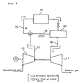
- Fig. 4 is a schematic view of a prior art pressurized fluidized bed combined cycle power system.
- fuel of coal or the like is burned at a pressurized fluidized bed boiler 13 so that steam system pipings thereof are heated to generate steam for drive of a steam turbine (not shown) as well as a high temperature combustion gas thereof, of about 800°C for example, is supplied into a gas turbine 11 via a duct 18 for drive thereof and its exhaust gas is discharged outside.
- the compressor outlet valve 14 is switched so that the air from the compressor 12 is taken into a starter combustor 30 as the combustion air via a duct 19, thus the gas turbine 11 is started by the starter combustor 30.
- the compressor outlet valve 14 is switched so that the air from the compressor 12 is stopped to flow into the starter combustor 30 and the gas turbine 11 is started by the high temperature combustion gas from the pressurized fluidized bed boiler 13 to come in an ordinary operation.
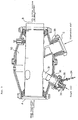
- Fig. 5 is a detailed cross sectional view of the starter combustor 30 mentioned above.
- the high temperature combustion gas from the pressurized fluidized bed boiler 13 enters portion A and gas generated, by combustion therein is supplied into the gas turbine 11 via portion B.
- Numeral 31 designates a pipe fitted to the combustor main unit.
- the pipe 31 comprises an inner cylinder 32 and there is disposed a fuel nozzle 33 close to one end of the inner cylinder 32. Light oil is supplied to the fuel nozzle 33 to be injected into the inner cylinder 32 for combustion in the combustor main unit.
- a fitting pipe 36 having a flame detector 34 fixed to its one end, is inserted into the inner cylinder 32 from outside so as to connect to an interior of the inner cylinder 32 for detection of flames.
- Numeral 39 designates a combustion air inlet and the air flowing through the compressor outlet valve 14 is led into the combustor main unit for combustion via portion C.
- Fig. 6 is a detailed cross sectional view of a flame detecting device including the flame detector 34 mentioned above.
- An adapter 35 having therein a through hole, has its one end fitted to the fitting pipe 36 and the flame detector 34 is fitted to the other end of the adapter 35.
- the fitting pipe 36 is fixed to the combustor main body and a pipe 38 is inserted in the fitting pipe 36 so as to connect at one end of the pipe 38 to the inner cylinder 32 and at the other end to the through hole of the adapter 35 and to the flame detector 34.
- Numeral 37 designates a glass plate provided to an end portion of the flame detector 34.
- the flame detector 34 fitted as mentioned above, there is incorporated a photoelectric element and state of flanges is detected through an end portion 38a of the pipe 38 opening to the inner cylinder 32 such that ultraviolet rays generated by the flames are led to the photoelectric element and state of the flames is detected by the strength thereof.
- the starter combustor 30 which is operated at a plant start for starting the gas turbine 11.
- operation of the starter combustor 30 is stopped so that the gas turbine 11 is driven by the high temperature gas from the boiler 13 for ordinary operation.
- the present invention provides the following means:
- the valve component having the recess portion, in the passage at the inlet portion of the flame detector and when the starter combustor is in operation, the passage is opened by the valve component so that the flames in the combustor may be detected. While the starter combustor is stopped, the passage is closed by the valve component and coal ash coming into the passage from the interior of the starter combustor in the ordinary operation time of the pressurized fluidized bed combined cycle power system is received to be collected in the recess portion of the valve component. While the passage is opened, the valve component is drawn out of the passage.
- the drive means is constructed by the rotatable and movable shaft and the manual handle, hence the handle is rotated manually to rotate the shaft and to move the valve component and the passage can be opened and closed.
- the drive means is constructed by the same shaft as in (3) above, the motor and the control means of the motor and when the burner of the starter combustor is ignited, the control means receives a signal thereof and drives the motor to rotate the shaft and to move the valve component to open the passage, hence the passage can be opened automatically at same time as the starter combustor starts and detection of the flames becomes possible.
- the control means rotates the motor reversely so that the passage is closed by the valve component.
- the flame detecting device of the present invention as described above, there is no fear of disorder of the flame detector due to the ash coming to the inlet portion of the flame detector of the starter combustor in the pressurized fluidized bed combined cycle power system to be accumulated on the glass plate and the starting of the gas turbine can be done safely.
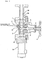
- Fig. 1 is a cross sectional view of a flame detecting device of combustor of one embodiment according to the present invention.
- numerals 32 to 34 and 36 to 38 designate parts or components having same functions as those shown in Fig. 5 with respect to the prior art device and description thereon will be omitted.
- Featured portions of the present invention, being portions shown by reference numerals 1 to 6, will be described below in detail.
- the flame detecting device of Fig. 1 is applicable to the starter combustor 30 in the pressurized fluidized bed combined cycle power system as described in Fig. 5.
- Numeral 1 designates a valve body, which is provided between the fitting pipe 36 and the flame detector 34 for connecting them mutually via a valve body passage 1a.
- Numeral 2 designates a shaft, which is provided movably as described later in an orthogonal direction to the valve body passage 1a of the valve body 1. There is fitted to an end of the shaft 2 a valve component 3 having a recess portion 3a. The valve component 3 is drawn out of and is pushed into the valve body passage 1a so that the valve body passage 1a is opened and closed.
- the shaft 2 is in a thread engagement with a threaded portion 6 of a handle fitting portion 5 so as to be rotatable and a handle 4 is connected to the other end of the shaft 2 so that the handle 4 is fitted to the valve body 1 via the shaft 2 and the handle fitting portion 5.
- the handle 4 is rotated, the shaft 2 is rotated around the threaded portion 6 to move toward a rightward direction in the figure as it rotates and the valve component 3 fitted to the end of the shaft 2 is drawn out of the valve body passage 1a, thus the valve body passage 1a is opened and the flame detector 34 thereunder is connected to the inner cylinder 32. If the passage 1a is to be closed, reverse action thereto is taken.
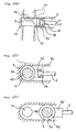
- Fig. 2 is a cross sectional view of a fitting state of the valve body 1 of the embodiment of Fig. 1, wherein Fig. 2(a) is a cross sectional side view showing the valve component 3 closing the valve body passage 1a, Fig. 2(b) is a plan view thereof and Fig. 2(c) shows the valve component 3 being retracted to open the valve body passage 1a.
- a shaft projection portion 2a is inserted rotatably.
- the shaft 2 being connected to the handle 4 as mentioned above, is rotated as the handle 4 is rotated and the shaft projection portion 2a at the end of the shaft 2 engages with the groove 3b of the shaft fitting portion 3a' so as to be rotatable therein.
- the shaft 2 is retracted toward the right side in the figure so that the valve component 3 is drawn out of the valve body passage 1a.
- Fig. 3 is a cross sectional view of a cleaning air nozzle applicable to the flame detecting device of the starter combustor of the embodiment according to the present invention.
- an air nozzle 12 is inserted from outside into the valve body passage 1a above the valve component 3 for supplying therefrom a pressurized air for cleaning via an air tube 11 connected to the air nozzle 12, so that the ash 40 piled in the recess portion 3a is blown to be cleaned immediately before the valve component 3 is drawn out.
- the ash 40 so blown goes up in the pipe 38 to flow out of an opening at the end portion 38a and to be mixed into the combustion gas coming from the pressurized fluidized bed boiler 13.
- Said blowing of the cleaning air is done such that, immediately before the valve component 3 is moved for opening the valve body passage 1a when the starter combustor 30 is to be driven, a valve (not shown) provided on the way of the air tube 11 is opened and the air is injected from the air nozzle 12 toward the recess portion 3a for blowing the ash 40.
- Fig. 2(c) shows the valve component 3 being drawn out of the valve body passage 1a so that the valve body passage 1a is opened.
- the valve component 3 can be drawn outside of the valve body passage 1a without the ash falling down on the glassy plate 37 of the flame detector 34 as there remains no ash 40 in the recess portion 3a as it has been blown off or even if there remains, still some in the recess portion 3a.
- the starter combustor 30 is started at the time of plant start for drive of the gas turbine 11 and in this case, it is necessary to watch the flame state in the combustor, hence the handle 4 is rotated for movement of the shaft 2 and the valve component 3 is drawn out of the valve body passage 1a so that the valve body passage 1a is opened.
- the ash 40 which had been collected in the recess portion 3a is blown off immediately before the valve component 3 is drawn out and then the valve component 3 is taken out of the valve body passage 1a. In this circumstance, the flame state in the combustor at the starting time can be confirmed.
- the starter combustor In the ordinary operation of the plant, the starter combustor is stopped and at this time, the high temperature combustion gas coming from the pressurized fluidized bed boiler 13 is supplied into the gas turbine 11 via the interior of the starter combustor 30.
- the handle 4 In this state, the handle 4 is rotated reversely in advance so that the shaft 2 is moved toward the direction of the valve body 1 and the valve component 3 is inserted in the valve body passage 1a, and the valve body passage 1a is closed completely as shown in Fig. 2(a).
- the gas turbine 11 is operated ordinarily by the high temperature combustion gas of the pressurized fluidized bed boiler 13.
- the ash 40 contained in the combustion gas comes in from the end portion 38a, which is open as shown in Fig. 1, to fall down in the pipe 38, as the inlet of the flame detector 34 is closed by the valve component 3, the ash is collected in the recess portion 3a of the valve component 3 as shown in Fig. 2(a) so as not to fall down further and there occurs no case of the glass plate 37 being dirtied.
- said handle 4 may be rotated manually for movement of the valve component 3 or an automatic system for movement of the valve component 3 may be employed. If an automatic system is to be employed, a control unit is associated, for example, with a burner igniting signal of the starter combustor so that the handle 4 is rotated by a motor etc. concurrently with starting of the starter combustor. Or, in place of the threaded portion 6, the shaft 2 is made slidable and an actuator is energized upon said signal so that the valve component 3 may be moved.
- the valve body passage 1a is closed by the valve component 3, thereby the ash coming through the pipe 38 in the ordinary operation time is collected in the recess portion 3a of the valve component 3 so as not to fall down further.
- the starter combustor is to be operated, the ash collected in the recess portion 3a is blown off by the air and then the valve component 3 is moved outside of the valve body passage 1a so that the valve body passage 1a is opened and the flames are detected by the flame detector 34.
- the present invention is not limited thereto but may be applied also to a flame detector of a coal gasifying combined cycle power system which comprises a similar combustor and a similar effect can be obtained in this case also.
- the present invention relates to a combustor flame detecting device for use in a gas turbine starter combustor in a pressurized fluidized bed combined cycle power system and by use of the construction as described above, there occurs no case of coal ash being accumulated on the glass plate at the inlet of the flame detector in the ordinary operation time, disorder of the flame detector can be prevented and reliability at the starting time of the gas turbine can be enhanced.
Landscapes
- Engineering & Computer Science (AREA)
- Chemical & Material Sciences (AREA)
- Combustion & Propulsion (AREA)
- Mechanical Engineering (AREA)
- General Engineering & Computer Science (AREA)
- Fluidized-Bed Combustion And Resonant Combustion (AREA)
- Control Of Combustion (AREA)
Abstract
In starter combustor of pressurized fluidized bed
combined cycle power system, disorder of flame detecting
device due to ash accumulation is prevented. Fuel nozzle 33
of starter combustor is provided to be directed to inner
cylinder 32 and pipe 38 of fitting pipe 36 is provided to
connect to the inner cylinder 32. Valve body 1, having valve
body passage 1a which connects to the pipe 38, is provided
to connect to one end of the fitting pipe 36 and valve
component 3, having recess portion 3a and connecting to shaft
2, is provided movably into and out of the valve body passage
1a. When the combustor is started, the shaft 2 which engages
rotatably with shaft fitting portion 3a' of the valve
component 3 and is in thread engagement with threaded portion
of the valve body 1 is moved by handle 4 being rotated so that
the valve component is moved and the passage 1a is opened.
While the combustor is stopped, the passage 1a is closed by
the valve component 3 being moved reversely. In ordinary
operation time, ash is collected in the recess portion 3a of
the valve component 3 and there occurs no accumulation of ash
on glass plate 37 thereunder and disorder of the flame
detecting device due to ash accumulation does not occur.
Description
The present invention relates generally to a flame
detecting device of a gas turbine starter combustor in a
pressurized fluidized bed combined cycle power system, and
specifically to that having a structure which is able to prevent
dirt due to combustion gas ash from sticking.
Fig. 4 is a schematic view of a prior art pressurized
fluidized bed combined cycle power system. In Fig. 4, fuel of
coal or the like is burned at a pressurized fluidized bed boiler
13 so that steam system pipings thereof are heated to generate
steam for drive of a steam turbine (not shown) as well as a high
temperature combustion gas thereof, of about 800°C for example,
is supplied into a gas turbine 11 via a duct 18 for drive thereof
and its exhaust gas is discharged outside.
Air from a compressor 12, which is driven by the gas
turbine 11, is supplied into the pressurized fluidized bed
boiler 13 as a combustion air via a compressor outlet valve 14.
On the other hand, at a plant start where the pressurized
fluidized bed boiler 13 is not in a sufficient operation yet,
because the high temperature combustion gas is not supplied
into the gas turbine 11 sufficiently yet via the duct 18, the
compressor outlet valve 14 is switched so that the air from the
compressor 12 is taken into a starter combustor 30 as the
combustion air via a duct 19, thus the gas turbine 11 is started
by the starter combustor 30.
When the pressurized fluidized bed boiler 13 is
heated to rise, the compressor outlet valve 14 is switched so
that the air from the compressor 12 is stopped to flow into the
starter combustor 30 and the gas turbine 11 is started by the
high temperature combustion gas from the pressurized fluidized
bed boiler 13 to come in an ordinary operation.
Fig. 5 is a detailed cross sectional view of the
starter combustor 30 mentioned above. In Fig. 5, the high
temperature combustion gas from the pressurized fluidized bed
boiler 13 enters portion A and gas generated, by combustion
therein is supplied into the gas turbine 11 via portion B.
Numeral 31 designates a pipe fitted to the combustor main unit.
The pipe 31 comprises an inner cylinder 32 and there is disposed
a fuel nozzle 33 close to one end of the inner cylinder 32. Light
oil is supplied to the fuel nozzle 33 to be injected into the
inner cylinder 32 for combustion in the combustor main unit.
A fitting pipe 36, having a flame detector 34 fixed
to its one end, is inserted into the inner cylinder 32 from
outside so as to connect to an interior of the inner cylinder
32 for detection of flames. Numeral 39 designates a combustion
air inlet and the air flowing through the compressor outlet
valve 14 is led into the combustor main unit for combustion via
portion C.
Fig. 6 is a detailed cross sectional view of a flame
detecting device including the flame detector 34 mentioned
above. An adapter 35, having therein a through hole, has its
one end fitted to the fitting pipe 36 and the flame detector
34 is fitted to the other end of the adapter 35. The fitting
pipe 36 is fixed to the combustor main body and a pipe 38 is
inserted in the fitting pipe 36 so as to connect at one end of
the pipe 38 to the inner cylinder 32 and at the other end to
the through hole of the adapter 35 and to the flame detector
34. Numeral 37 designates a glass plate provided to an end
portion of the flame detector 34.
In the flame detector 34 fitted as mentioned above,
there is incorporated a photoelectric element and state of
flanges is detected through an end portion 38a of the pipe 38
opening to the inner cylinder 32 such that ultraviolet rays
generated by the flames are led to the photoelectric element
and state of the flames is detected by the strength thereof.
In the pressurized fluidized bed combined cycle power
system as described above, there is provided the starter
combustor 30, which is operated at a plant start for starting
the gas turbine 11. When the pressurized fluidized bed boiler
13 rises, operation of the starter combustor 30 is stopped so
that the gas turbine 11 is driven by the high temperature gas
from the boiler 13 for ordinary operation. In the gas turbine
11 of such pressurized fluidized bed combined cycle power
system, fuel of coal or the like is burned by the pressurized
fluidized bed boiler 13 and the high temperature gas so
generated is used as an operating fluid, hence, while the plant
is in ordinary operation or while the pressurized fluidized bed
boiler 13 is being cooled after the plant is stopped, coal ash
contained in said operating fluid enters the flame detector 34
through the end portion 38a opening to the inner cylinder 32
and sticks to a surface of the glass plate 37 to lose a function
of the flame detector 34.
In view of such problem in the prior art flame
detecting device, it is an object of the present invention to
provide a flame detecting device for detecting a flame state
in a starter combustor etc. exposed to a high temperature
combustion gas containing coal ash as an operating fluid of a
gas turbine, in which even if coal ash etc. stick to a glass
plate of an inlet portion of the flame detector, it can be
removed and the flame detector functions well with none of
influence of ash sticking being given.
In order to achieve said object, the present
invention provides the following means:
In the invention of (1) above, there is provided the
valve component, having the recess portion, in the passage at
the inlet portion of the flame detector and when the starter
combustor is in operation, the passage is opened by the valve
component so that the flames in the combustor may be detected.
While the starter combustor is stopped, the passage is closed
by the valve component and coal ash coming into the passage from
the interior of the starter combustor in the ordinary operation
time of the pressurized fluidized bed combined cycle power
system is received to be collected in the recess portion of the
valve component. While the passage is opened, the valve
component is drawn out of the passage.
In the invention of (2) above, in addition to the
construction of (1) above, there is provided the air nozzle
system and when the passage is to be opened by the valve
component, immediately before that, the coal ash collected in
the recess portion of the valve component is blown off by the
air injected from the air nozzle system and then the valve
component is drawn out of the passage.
In the invention of (3) above, the drive means is
constructed by the rotatable and movable shaft and the manual
handle, hence the handle is rotated manually to rotate the shaft
and to move the valve component and the passage can be opened
and closed.
In the invention of (4) above, the drive means is
constructed by the same shaft as in (3) above, the motor and
the control means of the motor and when the burner of the starter
combustor is ignited, the control means receives a signal
thereof and drives the motor to rotate the shaft and to move
the valve component to open the passage, hence the passage can
be opened automatically at same time as the starter combustor
starts and detection of the flames becomes possible. Needless
to mention, when the burner of the starter combustor is stopped,
the control means rotates the motor reversely so that the
passage is closed by the valve component.
Further, in the invention of (5) above, in place of
the above motor, there is provided the actuator which is driven
linearly, hence the same function as in (4) above can be
effected by the linear movement of the actuator.
According to the flame detecting device of the
present invention as described above, there is no fear of
disorder of the flame detector due to the ash coming to the inlet
portion of the flame detector of the starter combustor in the
pressurized fluidized bed combined cycle power system to be
accumulated on the glass plate and the starting of the gas
turbine can be done safely.
Herebelow, description will be made concretely on
embodiments according to the present invention with reference
to the figures. Fig. 1 is a cross sectional view of a flame
detecting device of combustor of one embodiment according to
the present invention. In Fig. 1, numerals 32 to 34 and 36 to
38 designate parts or components having same functions as those
shown in Fig. 5 with respect to the prior art device and
description thereon will be omitted. Featured portions of the
present invention, being portions shown by reference numerals
1 to 6, will be described below in detail.
Like the prior art device, the flame detecting device
of Fig. 1 is applicable to the starter combustor 30 in the
pressurized fluidized bed combined cycle power system as
described in Fig. 5. Numeral 1 designates a valve body, which
is provided between the fitting pipe 36 and the flame detector
34 for connecting them mutually via a valve body passage 1a.
Numeral 2 designates a shaft, which is provided movably as
described later in an orthogonal direction to the valve body
passage 1a of the valve body 1. There is fitted to an end of
the shaft 2 a valve component 3 having a recess portion 3a. The
valve component 3 is drawn out of and is pushed into the valve
body passage 1a so that the valve body passage 1a is opened and
closed.
The shaft 2 is in a thread engagement with a threaded
portion 6 of a handle fitting portion 5 so as to be rotatable
and a handle 4 is connected to the other end of the shaft 2 so
that the handle 4 is fitted to the valve body 1 via the shaft
2 and the handle fitting portion 5. When the handle 4 is rotated,
the shaft 2 is rotated around the threaded portion 6 to move
toward a rightward direction in the figure as it rotates and
the valve component 3 fitted to the end of the shaft 2 is drawn
out of the valve body passage 1a, thus the valve body passage
1a is opened and the flame detector 34 thereunder is connected
to the inner cylinder 32. If the passage 1a is to be closed,
reverse action thereto is taken.
Fig. 2 is a cross sectional view of a fitting state
of the valve body 1 of the embodiment of Fig. 1, wherein Fig.
2(a) is a cross sectional side view showing the valve component
3 closing the valve body passage 1a, Fig. 2(b) is a plan view
thereof and Fig. 2(c) shows the valve component 3 being
retracted to open the valve body passage 1a.
In Figs. 2(a) and (b), when the valve is closed, there
is collected ash 40 in the recess portion 3a of the valve
component 3 and the valve component 3 is inserted into an
enlarged portion 1a' of the valve body passage 1a so that the
valve body passage 1a is closed completely and no ash 40 comes
in thereunder.
There is provided a shaft fitting portion 3a' in the
valve component 3 and a groove 3b is worked in the shaft fitting
portion 3a'. In the groove 3b, a shaft projection portion 2a
is inserted rotatably. The shaft 2, being connected to the
handle 4 as mentioned above, is rotated as the handle 4 is
rotated and the shaft projection portion 2a at the end of the
shaft 2 engages with the groove 3b of the shaft fitting portion
3a' so as to be rotatable therein. As the handle 4 is rotated,
the shaft 2 is retracted toward the right side in the figure
so that the valve component 3 is drawn out of the valve body
passage 1a.
In Figs. 2(a) and (b), when the ash 40 is collected
growingly to pile in the recess portion 3a, if the valve
component 3 is drawn out, there is a fear that the ash 40 so
piled in the recess portion 3a may be scraped by an edge of the
valve body passage 1a to fall down on a surface of the glass
plate. Hence, the ash 40 is blown as described later in Fig.
3, immediately before the valve component 3 is drawn out.
Fig. 3 is a cross sectional view of a cleaning air
nozzle applicable to the flame detecting device of the starter
combustor of the embodiment according to the present invention.
In Fig. 3, an air nozzle 12 is inserted from outside into the
valve body passage 1a above the valve component 3 for supplying
therefrom a pressurized air for cleaning via an air tube 11
connected to the air nozzle 12, so that the ash 40 piled in the
recess portion 3a is blown to be cleaned immediately before the
valve component 3 is drawn out. The ash 40 so blown goes up
in the pipe 38 to flow out of an opening at the end portion 38a
and to be mixed into the combustion gas coming from the
pressurized fluidized bed boiler 13.
Said blowing of the cleaning air is done such that,
immediately before the valve component 3 is moved for opening
the valve body passage 1a when the starter combustor 30 is to
be driven, a valve (not shown) provided on the way of the air
tube 11 is opened and the air is injected from the air nozzle
12 toward the recess portion 3a for blowing the ash 40.
Fig. 2(c) shows the valve component 3 being drawn out
of the valve body passage 1a so that the valve body passage 1a
is opened. The valve component 3 can be drawn outside of the
valve body passage 1a without the ash falling down on the glassy
plate 37 of the flame detector 34 as there remains no ash 40
in the recess portion 3a as it has been blown off or even if
there remains, still some in the recess portion 3a.
In the flame detecting device of the embodiment
constructed as mentioned above, the starter combustor 30 is
started at the time of plant start for drive of the gas turbine
11 and in this case, it is necessary to watch the flame state
in the combustor, hence the handle 4 is rotated for movement
of the shaft 2 and the valve component 3 is drawn out of the
valve body passage 1a so that the valve body passage 1a is opened.
At this time, the ash 40 which had been collected in the recess
portion 3a is blown off immediately before the valve component
3 is drawn out and then the valve component 3 is taken out of
the valve body passage 1a. In this circumstance, the flame
state in the combustor at the starting time can be confirmed.
In the ordinary operation of the plant, the starter
combustor is stopped and at this time, the high temperature
combustion gas coming from the pressurized fluidized bed boiler
13 is supplied into the gas turbine 11 via the interior of the
starter combustor 30. In this state, the handle 4 is rotated
reversely in advance so that the shaft 2 is moved toward the
direction of the valve body 1 and the valve component 3 is
inserted in the valve body passage 1a, and the valve body
passage 1a is closed completely as shown in Fig. 2(a).
As mentioned above, while the valve body passage 1a
is closed by the valve component 3, the gas turbine 11 is
operated ordinarily by the high temperature combustion gas of
the pressurized fluidized bed boiler 13. At this time, although
the ash 40 contained in the combustion gas comes in from the
end portion 38a, which is open as shown in Fig. 1, to fall down
in the pipe 38, as the inlet of the flame detector 34 is closed
by the valve component 3, the ash is collected in the recess
portion 3a of the valve component 3 as shown in Fig. 2(a) so
as not to fall down further and there occurs no case of the glass
plate 37 being dirtied. Hence, there is no fear of non-functioning
of the flame detector 34 due to the ash 40 being
accumulated on the surface of the glass plate 37.
It is to be noted that said handle 4 may be rotated
manually for movement of the valve component 3 or an automatic
system for movement of the valve component 3 may be employed.
If an automatic system is to be employed, a control unit is
associated, for example, with a burner igniting signal of the
starter combustor so that the handle 4 is rotated by a motor
etc. concurrently with starting of the starter combustor. Or,
in place of the threaded portion 6, the shaft 2 is made slidable
and an actuator is energized upon said signal so that the valve
component 3 may be moved.
According to the embodiment as described above, while
the starter combustor is not in use, the valve body passage 1a
is closed by the valve component 3, thereby the ash coming
through the pipe 38 in the ordinary operation time is collected
in the recess portion 3a of the valve component 3 so as not to
fall down further. When the starter combustor is to be operated,
the ash collected in the recess portion 3a is blown off by the
air and then the valve component 3 is moved outside of the valve
body passage 1a so that the valve body passage 1a is opened and
the flames are detected by the flame detector 34.
Further, if a large amount of ash is collected in the
recess portion 3a of the valve component 3, air is injected for
dispersing the ash into the combustor, thereby there occurs no
accumulation of the ash on the surface of the glass plate 37
of the flame detector 34. Thus, disorder of the flame detector
due to accumulation of the coal ash can be prevented securely.
It is to be noted that although an example of the flame
detector used in the starter combustor of the pressurized
fluidized bed combined cycle power system has been described
in the above embodiment, the present invention is not limited
thereto but may be applied also to a flame detector of a coal
gasifying combined cycle power system which comprises a similar
combustor and a similar effect can be obtained in this case
also.
The present invention relates to a combustor flame
detecting device for use in a gas turbine starter combustor in
a pressurized fluidized bed combined cycle power system and by
use of the construction as described above, there occurs no case
of coal ash being accumulated on the glass plate at the inlet
of the flame detector in the ordinary operation time, disorder
of the flame detector can be prevented and reliability at the
starting time of the gas turbine can be enhanced.
Claims (5)
- A combustor flame detecting device for use in a gas turbine starter combustor in a pressurized fluidized bed combined cycle power system in which a gas turbine is driven by a combustion gas from a pressurized fluidized bed boiler, characterized in comprising a flame detector (34) connected to a passage (1a) connecting to an interior of said starter combustor; a valve component (3) provided in said passage (1a) at an inlet portion of said flame detector (34) and having a recess portion (3a) for receiving ash (40) coming into said flame detector (34) from the interior of said starter combustor; and a drive means of said valve component (3) for opening and closing said passage (1a).
- A combustor flame detecting device for use in a gas turbine starter combustor in a pressurized fluidized bed combined cycle power system in which a gas turbine is driven by a combustion gas from a pressurized fluidized bed boiler, characterized in comprising a flame detector (34) connected to a passage (1a) connecting to an interior of said starter combustor; a valve component (3) provided in said passage (1a) at an inlet portion of said flame detector (34) and having a recess portion (3a) for receiving ash (40) coming into said flame detector (34) from the interior of said starter combustor; a drive means of said valve component (3) for opening and closing said passage (1a); and an air nozzle (12) system provided to pass through into said passage (1a) from outside of said passage (1a) for blowing a pressurized cleaning air to the vicinity of the recess portion (3a) of said valve component (3).
- A combustor flame detecting device as claimed in Claim 1 or 2, characterized in that said drive means comprises a shaft (2) which is connected rotatably to said valve component (3) and is movable in a direction orthogonal to said passage (1a) by being rotated in a thread engagement with a threaded portion (6) provided in a valve body; and a manual handle (4) connected to said shaft (2).
- A combustor flame detecting device as claimed in Claim 1 or 2, characterized in that said drive means comprises a shaft (2) which is connected rotatably to said valve component (3) and is movable in a direction orthogonal to said passage (1a) by being rotated in a thread engagement with a threaded portion (6) provided in a valve body; a motor connected to said shaft (2); and a control means for controlling said motor and characterized in that said control means is associated with a burner igniting signal of said starter combustor to rotate said shaft (2) for movement of said valve component (3).
- A combustor flame detecting device as claimed in Claim 1 or 2, characterized in that said drive means comprises a shaft (2) which is connected rotatably to said valve component (3) and is movable in a direction orthogonal to said passage (1a); an actuator connected to said shaft (2); and a control means for controlling said actuator and characterized in that said control means is associated with a burner igniting signal of said starter combustor for movement of said valve component (3).
Applications Claiming Priority (3)
| Application Number | Priority Date | Filing Date | Title |
|---|---|---|---|
| JP12966397A JP3294151B2 (en) | 1997-05-20 | 1997-05-20 | Combustor flame detector |
| JP129663/97 | 1997-05-20 | ||
| PCT/JP1998/002114 WO1998053254A1 (en) | 1997-05-20 | 1998-05-13 | Flame detector for combustor |
Publications (2)
| Publication Number | Publication Date |
|---|---|
| EP0919773A1 true EP0919773A1 (en) | 1999-06-02 |
| EP0919773A4 EP0919773A4 (en) | 2005-09-21 |
Family
ID=15015080
Family Applications (1)
| Application Number | Title | Priority Date | Filing Date |
|---|---|---|---|
| EP98919582A Withdrawn EP0919773A4 (en) | 1997-05-20 | 1998-05-13 | Flame detector for combustor |
Country Status (5)
| Country | Link |
|---|---|
| US (1) | US6141957A (en) |
| EP (1) | EP0919773A4 (en) |
| JP (1) | JP3294151B2 (en) |
| CA (1) | CA2261744C (en) |
| WO (1) | WO1998053254A1 (en) |
Cited By (6)
| Publication number | Priority date | Publication date | Assignee | Title |
|---|---|---|---|---|
| WO2006083356A3 (en) * | 2004-11-18 | 2009-01-08 | Applied Materials Inc | Safety, monitoring and control system for thermal reactor |
| US7569193B2 (en) | 2003-12-19 | 2009-08-04 | Applied Materials, Inc. | Apparatus and method for controlled combustion of gaseous pollutants |
| US7700049B2 (en) | 2005-10-31 | 2010-04-20 | Applied Materials, Inc. | Methods and apparatus for sensing characteristics of the contents of a process abatement reactor |
| US7736599B2 (en) | 2004-11-12 | 2010-06-15 | Applied Materials, Inc. | Reactor design to reduce particle deposition during process abatement |
| US8095240B2 (en) | 2004-11-18 | 2012-01-10 | Applied Materials, Inc. | Methods for starting and operating a thermal abatement system |
| EP2857747A4 (en) * | 2012-05-30 | 2015-12-23 | Tsukishima Kikai Co | METHOD FOR TRANSPORTING IMPURITIES IN A PRESSED FLUIDIZED OVEN SYSTEM |
Families Citing this family (9)
| Publication number | Priority date | Publication date | Assignee | Title |
|---|---|---|---|---|
| US6556141B2 (en) | 2001-05-14 | 2003-04-29 | PIA Procédé Industriel Automatisé Inc. | Apparatus and method for detecting the presence of a burner flame |
| KR100973895B1 (en) * | 2003-06-09 | 2010-08-03 | 주식회사 포스코 | Flame detection device with cooling function |
| JP5419378B2 (en) * | 2008-04-11 | 2014-02-19 | 三菱重工業株式会社 | Flame detector mounting structure |
| GB2466305B (en) * | 2008-12-19 | 2015-06-03 | Autoflame Eng Ltd | Burner installation |
| WO2011079422A1 (en) * | 2009-12-30 | 2011-07-07 | 北京航天万源煤化工工程技术有限公司 | Flame detecting device |
| US8601861B1 (en) | 2012-08-10 | 2013-12-10 | General Electric Company | Systems and methods for detecting the flame state of a combustor of a turbine engine |
| CN104048750B (en) * | 2014-06-30 | 2016-05-11 | 四川天微电子有限责任公司 | A kind of flame detection device |
| KR102330555B1 (en) * | 2020-01-10 | 2021-11-26 | 한국전력공사 | Flame position measurement system and measuring method the same |
| CN115949505A (en) * | 2021-10-07 | 2023-04-11 | 通用电气公司 | Flame Detector Lens Maintenance System |
Family Cites Families (10)
| Publication number | Priority date | Publication date | Assignee | Title |
|---|---|---|---|---|
| LU52435A1 (en) * | 1966-11-24 | 1968-06-25 | ||
| JPS5347407U (en) * | 1976-09-27 | 1978-04-21 | ||
| US4306835A (en) * | 1979-11-20 | 1981-12-22 | Avco Corporation | Air purging unit for an optical pyrometer of a gas turbine engine |
| JPH01159423A (en) * | 1987-12-16 | 1989-06-22 | Hitachi Ltd | Combustion safety device for combustor |
| US4981088A (en) * | 1990-05-14 | 1991-01-01 | Diamond Electronics, Inc. | Slag eliminator for furnace viewing system |
| JPH05195818A (en) * | 1992-01-20 | 1993-08-03 | Hitachi Ltd | Combustor of gas turbine |
| JPH0693882A (en) * | 1992-09-11 | 1994-04-05 | Nissan Motor Co Ltd | Control device for combustor |
| US5578828A (en) * | 1994-11-15 | 1996-11-26 | General Electric Company | Flame sensor window coating compensation |
| JPH09133023A (en) * | 1995-11-13 | 1997-05-20 | Toshiba Corp | Gas turbine combustion equipment |
| US5829962A (en) * | 1996-05-29 | 1998-11-03 | L'air Liquide, Societe Anonyme Pour L'etude Et, L'exploitation Des Procedes Georges | Method and apparatus for optical flame control of combustion burners |
-
1997
- 1997-05-20 JP JP12966397A patent/JP3294151B2/en not_active Expired - Fee Related
-
1998
- 1998-05-13 EP EP98919582A patent/EP0919773A4/en not_active Withdrawn
- 1998-05-13 US US09/214,928 patent/US6141957A/en not_active Expired - Fee Related
- 1998-05-13 WO PCT/JP1998/002114 patent/WO1998053254A1/en not_active Ceased
- 1998-05-13 CA CA002261744A patent/CA2261744C/en not_active Expired - Fee Related
Cited By (10)
| Publication number | Priority date | Publication date | Assignee | Title |
|---|---|---|---|---|
| US7569193B2 (en) | 2003-12-19 | 2009-08-04 | Applied Materials, Inc. | Apparatus and method for controlled combustion of gaseous pollutants |
| US7736599B2 (en) | 2004-11-12 | 2010-06-15 | Applied Materials, Inc. | Reactor design to reduce particle deposition during process abatement |
| US7985379B2 (en) | 2004-11-12 | 2011-07-26 | Applied Materials, Inc. | Reactor design to reduce particle deposition during process abatement |
| WO2006083356A3 (en) * | 2004-11-18 | 2009-01-08 | Applied Materials Inc | Safety, monitoring and control system for thermal reactor |
| US7682574B2 (en) | 2004-11-18 | 2010-03-23 | Applied Materials, Inc. | Safety, monitoring and control features for thermal abatement reactor |
| US8095240B2 (en) | 2004-11-18 | 2012-01-10 | Applied Materials, Inc. | Methods for starting and operating a thermal abatement system |
| US7700049B2 (en) | 2005-10-31 | 2010-04-20 | Applied Materials, Inc. | Methods and apparatus for sensing characteristics of the contents of a process abatement reactor |
| US7736600B2 (en) | 2005-10-31 | 2010-06-15 | Applied Materials, Inc. | Apparatus for manufacturing a process abatement reactor |
| EP2857747A4 (en) * | 2012-05-30 | 2015-12-23 | Tsukishima Kikai Co | METHOD FOR TRANSPORTING IMPURITIES IN A PRESSED FLUIDIZED OVEN SYSTEM |
| US10001277B2 (en) | 2012-05-30 | 2018-06-19 | Tsukishima Kikai Co., Ltd. | Method for conveying impurities in pressurized fluidized bed incinerator system |
Also Published As
| Publication number | Publication date |
|---|---|
| US6141957A (en) | 2000-11-07 |
| JP3294151B2 (en) | 2002-06-24 |
| WO1998053254A1 (en) | 1998-11-26 |
| CA2261744C (en) | 2003-01-07 |
| CA2261744A1 (en) | 1998-11-26 |
| JPH10318540A (en) | 1998-12-04 |
| EP0919773A4 (en) | 2005-09-21 |
Similar Documents
| Publication | Publication Date | Title |
|---|---|---|
| CA2261744C (en) | Combustor flame detecting device | |
| US8234874B2 (en) | Systems and methods for bypassing an inlet air treatment filter | |
| KR101016083B1 (en) | Start stop method and start stop control device for gas turbine | |
| US7664590B2 (en) | System for detecting ignition failure in a gas turbine engine | |
| US5095694A (en) | Fuel purging system for a turbine engine | |
| CN102455000A (en) | System and method for igniting a combustor | |
| US4823843A (en) | Valve apparatus | |
| JP3039589B2 (en) | Gas turbine and gas turbine combustion device | |
| JPH0710021Y2 (en) | Reburner for particulate trap | |
| KR0146011B1 (en) | Combustion stop device during incomplete combustion of combustion equipment | |
| KR100882966B1 (en) | Safety devices for cleaning systems of gas turbine liquid fuel burners | |
| JP3500884B2 (en) | Gas ignition method in coke oven riser | |
| RU2018011C1 (en) | Apparatus for starting gas-turbine plant | |
| KR200227169Y1 (en) | Burner gun fuel leakage prevention device | |
| JPS6319715Y2 (en) | ||
| EP1060347B1 (en) | Integrated security system for smoke extractor | |
| SU1752311A1 (en) | Device for blocking and protection of tea drying unit | |
| CN120991612A (en) | Automatic window cleaning device that prevents the accumulation of dust and molten material. | |
| JPH0533918A (en) | Blast opening-cleaning device | |
| KR101562186B1 (en) | boiler using petro coke | |
| CN119436155A (en) | A pyrolysis combustion chamber structure for solid waste treatment | |
| JPH09133023A (en) | Gas turbine combustion equipment | |
| KR101248500B1 (en) | Burner for solid fuel | |
| JPH1114028A (en) | Combustion control method of stoker type garbage incinerator and apparatus therefor | |
| KR19990003427A (en) | Combustion device and control method of combustion device |
Legal Events
| Date | Code | Title | Description |
|---|---|---|---|
| PUAI | Public reference made under article 153(3) epc to a published international application that has entered the european phase |
Free format text: ORIGINAL CODE: 0009012 |
|
| 17P | Request for examination filed |
Effective date: 19990114 |
|
| AK | Designated contracting states |
Kind code of ref document: A1 Designated state(s): CH DE FR GB IT LI |
|
| A4 | Supplementary search report drawn up and despatched |
Effective date: 20050808 |
|
| GRAP | Despatch of communication of intention to grant a patent |
Free format text: ORIGINAL CODE: EPIDOSNIGR1 |
|
| STAA | Information on the status of an ep patent application or granted ep patent |
Free format text: STATUS: THE APPLICATION IS DEEMED TO BE WITHDRAWN |
|
| 18D | Application deemed to be withdrawn |
Effective date: 20080708 |