EP0919271A1 - Fliehkraftabscheider mit Prallplatte - Google Patents
Fliehkraftabscheider mit Prallplatte Download PDFInfo
- Publication number
- EP0919271A1 EP0919271A1 EP98113490A EP98113490A EP0919271A1 EP 0919271 A1 EP0919271 A1 EP 0919271A1 EP 98113490 A EP98113490 A EP 98113490A EP 98113490 A EP98113490 A EP 98113490A EP 0919271 A1 EP0919271 A1 EP 0919271A1
- Authority
- EP
- European Patent Office
- Prior art keywords
- chamber
- liquid
- air
- interior wall
- centrifugal separator
- Prior art date
- Legal status (The legal status is an assumption and is not a legal conclusion. Google has not performed a legal analysis and makes no representation as to the accuracy of the status listed.)
- Withdrawn
Links
- 239000007788 liquid Substances 0.000 claims abstract description 52
- XLYOFNOQVPJJNP-UHFFFAOYSA-N water Substances O XLYOFNOQVPJJNP-UHFFFAOYSA-N 0.000 claims description 55
- 239000002274 desiccant Substances 0.000 claims description 36
- 238000007605 air drying Methods 0.000 claims description 18
- 238000001035 drying Methods 0.000 claims description 12
- 238000004140 cleaning Methods 0.000 claims description 10
- 239000000203 mixture Substances 0.000 claims description 10
- 239000013618 particulate matter Substances 0.000 claims description 10
- 239000000463 material Substances 0.000 claims description 7
- 238000010926 purge Methods 0.000 description 23
- 239000007789 gas Substances 0.000 description 16
- 230000007246 mechanism Effects 0.000 description 5
- 230000008901 benefit Effects 0.000 description 4
- 239000007791 liquid phase Substances 0.000 description 4
- 238000000926 separation method Methods 0.000 description 4
- 238000005266 casting Methods 0.000 description 3
- 230000000694 effects Effects 0.000 description 3
- 238000012423 maintenance Methods 0.000 description 3
- 230000000712 assembly Effects 0.000 description 2
- 238000000429 assembly Methods 0.000 description 2
- 239000000428 dust Substances 0.000 description 2
- 239000007792 gaseous phase Substances 0.000 description 2
- 230000000737 periodic effect Effects 0.000 description 2
- IJJWOSAXNHWBPR-HUBLWGQQSA-N 5-[(3as,4s,6ar)-2-oxo-1,3,3a,4,6,6a-hexahydrothieno[3,4-d]imidazol-4-yl]-n-(6-hydrazinyl-6-oxohexyl)pentanamide Chemical compound N1C(=O)N[C@@H]2[C@H](CCCCC(=O)NCCCCCC(=O)NN)SC[C@@H]21 IJJWOSAXNHWBPR-HUBLWGQQSA-N 0.000 description 1
- 230000009471 action Effects 0.000 description 1
- 238000004891 communication Methods 0.000 description 1
- 239000012141 concentrate Substances 0.000 description 1
- 239000000356 contaminant Substances 0.000 description 1
- 238000011161 development Methods 0.000 description 1
- 238000004090 dissolution Methods 0.000 description 1
- 238000010348 incorporation Methods 0.000 description 1
- 238000012986 modification Methods 0.000 description 1
- 230000004048 modification Effects 0.000 description 1
- 239000003921 oil Substances 0.000 description 1
- 239000011236 particulate material Substances 0.000 description 1
- 239000012071 phase Substances 0.000 description 1
- 230000002035 prolonged effect Effects 0.000 description 1
- 230000001172 regenerating effect Effects 0.000 description 1
- 238000007789 sealing Methods 0.000 description 1
- 239000000126 substance Substances 0.000 description 1
Images


Classifications
-
- B—PERFORMING OPERATIONS; TRANSPORTING
- B01—PHYSICAL OR CHEMICAL PROCESSES OR APPARATUS IN GENERAL
- B01D—SEPARATION
- B01D45/00—Separating dispersed particles from gases or vapours by gravity, inertia, or centrifugal forces
- B01D45/12—Separating dispersed particles from gases or vapours by gravity, inertia, or centrifugal forces by centrifugal forces
- B01D45/16—Separating dispersed particles from gases or vapours by gravity, inertia, or centrifugal forces by centrifugal forces generated by the winding course of the gas stream, the centrifugal forces being generated solely or partly by mechanical means, e.g. fixed swirl vanes
-
- B—PERFORMING OPERATIONS; TRANSPORTING
- B01—PHYSICAL OR CHEMICAL PROCESSES OR APPARATUS IN GENERAL
- B01D—SEPARATION
- B01D53/00—Separation of gases or vapours; Recovering vapours of volatile solvents from gases; Chemical or biological purification of waste gases, e.g. engine exhaust gases, smoke, fumes, flue gases, aerosols
- B01D53/26—Drying gases or vapours
- B01D53/261—Drying gases or vapours by adsorption
-
- B—PERFORMING OPERATIONS; TRANSPORTING
- B04—CENTRIFUGAL APPARATUS OR MACHINES FOR CARRYING-OUT PHYSICAL OR CHEMICAL PROCESSES
- B04C—APPARATUS USING FREE VORTEX FLOW, e.g. CYCLONES
- B04C5/00—Apparatus in which the axial direction of the vortex is reversed
- B04C5/08—Vortex chamber constructions
- B04C5/103—Bodies or members, e.g. bulkheads, guides, in the vortex chamber
-
- Y—GENERAL TAGGING OF NEW TECHNOLOGICAL DEVELOPMENTS; GENERAL TAGGING OF CROSS-SECTIONAL TECHNOLOGIES SPANNING OVER SEVERAL SECTIONS OF THE IPC; TECHNICAL SUBJECTS COVERED BY FORMER USPC CROSS-REFERENCE ART COLLECTIONS [XRACs] AND DIGESTS
- Y10—TECHNICAL SUBJECTS COVERED BY FORMER USPC
- Y10S—TECHNICAL SUBJECTS COVERED BY FORMER USPC CROSS-REFERENCE ART COLLECTIONS [XRACs] AND DIGESTS
- Y10S55/00—Gas separation
- Y10S55/17—Compressed air water removal
Definitions
- the present invention generally relates to a new and improved centrifugal liquid-gas separator. More particularly, the present invention pertains to a centrifugal separator for removing a liquid phase from a compressed gas, the centrifugal separator having a baffle to divide the separator chamber into two sub-chambers which function to better and more completely separate the liquid from the compressed gas by reducing turbulence in the lower chamber when the drain valve is opened to drain the accumulated liquid therefrom.
- a Westinghouse Air Brake Company C-1 air dryer is designed to remove moisture from compressed air for use in a compressed air system as utilized on railway trains, transit vehicles and the like, as necessary to operate the air brake system and air valves.
- United States Patent No. 5,423,129 assigned to the assignee of this invention and cited above, discloses such a system wherein the compressed air is cleaned and dried by passing it through a regenerating system containing a desiccant material to absorb the moisture and filter-out particulate matter. The desiccant is regenerated by passing a small percentage of the dried air back therethrough which absorbs at least some of the moisture collected in the desiccant and is therefore discarded.
- the above noted prior art air drying system receives compressed air from a conventional air compressor, a supply which typically contains an unacceptably high amount of moisture and other particulates suspended therein.
- This unpurified compressed air is caused to flow upwardly through a desiccant material usually in the form of a porous cartridge containing a porous desiccant media.
- the desiccant plays the key role within the single tower air drying system in that it absorbs the moisture and traps various particulates (e.g., dust, dirt, etc.) as the compressed air moves upwardly through the desiccant media.
- the cleaned and dried compressed air continues flowing from the desiccant media through a purge check valve situated near the top of the tower. This purified compressed air then passes through a side chamber, a part of which eventually reaches a purge volume.
- the system When the air compressor is cycled off, the system operates in a purge mode. During the purge mode, the purified pressurized air contained within the purge volume passes slowly in the reverse direction through a choke in a purge check valve and then back through the desiccant media. This slow stream of dried air reabsorbs a portion of the moisture previously collected within the desiccant media. Having evaporated into this passing stream of dry air, the evaporated moisture eventually exhausts through the sump volume to atmosphere. This gradual purging of dry air back through the system serves to dry out and thus rejuvenate or regenerate the desiccant media.
- the air compressor is again cycled on, the tower system returns to operation in a drying mode, with the desiccant media then again removing moisture from the stream of unpurified compressed air passing therethrough.
- twin tower system has been proposed and developed in which a pair of desiccant containing chambers or towers are provided, each alternating back and forth between operation in drying mode and in recycle mode. Accordingly, at any given moment of operation, one tower is operating in air drying cycle while the other is operating in recycle mode or purge cycle.
- a pair of control valves are provided to automatically switch the flow to reverse these flow directions so that after a defined time period the cycles are reversed so that in effect a continuous operation is achieved with each tower alternately operating in drying mode permitting moisture to collect within the desiccant media while the other tower is in recycle mode removing the collected moisture from the desiccant material or media.
- This unique system obviously had a greater moisture removing capability and also avoids the need to have the source of unpurified air cycled-off in order to purge the desiccant material of the moisture it has accumulated, and thereby eliminate the need to temporarily deprive the pneumatic system of a steady supply of clean and dried compressed air while the compressor is turned off.
- the switching of the two drying assemblies alternately between the drying and the purging modes allows the twin tower system to exsiccate the air stream more efficiently than the prior art single tower system.
- Two desiccant towers rather than one are employed in the air drying system with one absorbing moisture while the other is being purged of it.
- the switching of the two drying assemblies alternately between the drying and the purging modes thus serves to continuously purge moisture from the twin tower system. More fully desiccated air is thus supplied to the pneumatic system.
- the amount, density and overall surface area of the desiccant can also be selected to suit varying needs.
- the twin tower system can be applied to a wide variety of pneumatic systems.
- Typical of the types of pneumatic systems to which the twin tower system could be applied include the pneumatic brake systems of passenger and freight railroad trains, subway trains and various other types of rail related transportation systems. Further examples include the pneumatic brake systems of various truck transport vehicles. Other types of pneumatic systems to which the twin tower system could be applied may be found outside the transportation field.
- Another disadvantage of the single tower air drying system is that it is only capable of removing a certain, limited amount of moisture during the purge mode. Because the volume of unpurified air flowing into the system to be dried vastly exceeds the volume of purified air used to purge the desiccant media, the desiccant media never adequately exsiccates during operation of the single tower system. Indeed, the desiccant media adequately exsiccates only after the system has been turned off for a prolonged time sufficient to accomplish same. While the twin tower system has a greatly increased water removing capacity, it is still not as great as would be desired for completely trouble free operation. Accordingly, other type of water removing systems have been considered and examined for combining into the above twin tower system in an effort to maximize its water removing capability. Most such systems, however, require the use of moving parts or coalescing filters which would significantly increase maintenance costs or unduly complicate the system.
- centrifugal separator which has been shown to be rather effective for removing moisture from air in low pressure systems. Indeed, centrifugal separators have utilized in twin tower air drying systems, but with only a moderate degree of success.
- a compressed air system where the air is conveyed under a considerable pressure, the high pressure of the compressed air causes a very significant turbulence within the centrifugal separator when the drain is opened to permit the water to be drained therefrom. This turbulence causes the surface tension of any separated water within the separator to be broken-up to such a degree that water is caused to redissolve within the turbulent compressed air, thereby virtually defeating the very purpose for the separator.
- the inventive centrifugal separator includes a baffle or separator disk within the centrifugal chamber which serves to separate the centrifugal chamber into an upper sub-chamber and a lower sub-chamber.
- the baffle does not contact the circular walls of the chamber so that it is insufficient to prevent the downward flow of separated water along the interior wall of the separator, or to prevent flow or movement of compressed air from one sub-chamber to the other.
- the baffle will be sufficient to prevent, or at least significantly minimize, air turbulence, at least within the lower sub-chamber when collected water is drained therefrom.
- the brake-up of surface tension of collected water in the lower sub-chamber is significantly reduced so that the tendency for such water to redissolve into the compressed air is significantly minimized.
- the centrifugal separator of this invention is particularly ideal for separating a liquid from a compressed gas, and particularly for separating water from compressed air, which pursuant to conventional centrifugal separators comprises a chamber having a generally circular interior wall, either cylindrical or conical, with a vertically disposed axis, and at least one tangential inlet for admitting the mixture of compressed gas and liquid into the chamber such that the mixture is caused to cyclonically revolve within the separator chamber at a velocity sufficient to cause the liquid to collect on the circular interior wall as a result of centrifugal forces, and flow downwardly along the interior wall as a result of gravitational forces.
- a sump is provided within the chamber which is adapted to collect the liquid flowing downwardly along the interior wall, an outlet provided for draining the collected liquid from the sump.
- An air vent is also provided in an upper portion of the chamber for permitting the compressed gas to exit from the chamber after the liquid has been separated therefrom.
- the crux of this invention resides in a baffle or separator disk which is horizontally disposed within the chamber having a generally circular edge spaced from the interior wall sufficiently to generally separate said chamber into an upper sub-chamber and a lower sub-chamber but insufficient to prevent downward flow of separated liquid downwardly along the interior wall, so that such flow will progress from the upper sub-chamber into the lower sub-chamber.
- the baffle is preferable further provided with a plurality of apertures circumferentially spaced around the perimeter adjacent to the circular edge.
- the baffle causes the cyclonic motion to be concentrated within the upper sub-chamber so that when the collected water is drained from the sump, any turbulent motion thereof caused by the pressure differential created in the lower sub-chamber will be significantly reduced, thereby also significantly reducing any tendency for the separated water in the lower sub-chamber to be redissolved into the de-watered air.
- centrifugal separator as described above is unique and novel in and of itself as a liquid-gas separator
- its incorporation into a compressed air drying system utilizing a desiccant as described above is also unique and novel in that a significant volume of water is removed from the compressed air before the compressed air is conveyed through the desiccant for further and more complete drying.
- the combination of the unique centrifugal separator of this invention with a twin tower, or even a single tower, air drying system utilizing a desiccant the compressed air can be dried to exceptionally dry and clean level so that even if the temperature thereof is significantly reduced, the dew point can be maintained low enough that water is not caused to condense therefrom. Accordingly, the combination provides a much improved air cleaning and drying system without adding significantly to the overall cost of the system, and without adding any moving parts or complicated parts which would add to the system's maintenance costs.
- centrifugal separator particularly suited for separating a liquid phase from a compressed gaseous phase, and ideally suited for separating water or moisture from compressed air.
- a further object of this invention is to provide an improved centrifugal separator for removing liquid or moisture from a gas which works adequately even though the inlet gas may be under significant pressure.
- An even further object of this invention is to provide a simple and low cost separator for removing water from compressed air as may be advantageously incorporated into a desiccant containing twin tower compressed air drying and cleaning system.
- Still a further object of this invention is to provide new and improved, desiccant containing, twin tower system for cleaning and drying compressed air in which the moisture content of the compressed air can be reduced to exceptionally low levels.
- Still an even further object of this invention is to provide new and improved, desiccant containing, twin tower system for cleaning and drying compressed air in which the moisture content of the compressed air is reduced before it is conveyed through the desiccant material thereby reducing the amount of water in need of removal from the desiccant during the purge cycle.
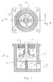
- the separator 10 comprises a cylindrical canister-like body 12 having a cylindrical chamber 14 therein with a generally cylindrical interior wall with a vertically disposed axis.
- the base of cylindrical chamber 14 is provided with a slopped floor 16, which in essence forms a floor of a sump 18 for collecting separated water after it is separated from the compressed air.
- a drain outlet 20 having a valve 22 is provided to controllably drain collected the water from the sump 18.
- a cover member 24 is provided not only to closed chamber 14, but to provide inlet means 25 for admitting the mixture to be separated (i.e., moist compressed air) into chamber 14.
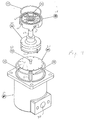
- the cover 24 and inlet means 25 are independent components, with the inlet means 25 bolted to the undersurface of cover member 24, as in actual practice, it is intended that the centrifugal separator 10 will be attached to the bottom of the casting containing the twin towers.
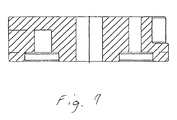
- inlet means 25 is provided with four inlet ports 26 for admitting the air-water mixture into chamber 14 tangentially to the circular configuration of chamber 14.
- inlet means 25 is provided with an annular chamber 27 into which the compressed gas is admitted, and the tangent inlet ports 26 are each in communication with the annular chamber 27.
- Annular chamber 27 is closed by being bolted against cover member 24. Accordingly, the incoming moist air will be caused to cyclonically revolve within chamber 14 at a velocity sufficient to cause the water to condense and collect on the cylindrical interior wall of chamber 14 as a result of centrifugal forces, and as the concentration thereof increases, to flow downwardly along that interior wall as a result of gravitational forces, eventually collecting as a pool in the sump 18.
- the compressed air on the other hand, having a lower mass than the water, will continue its cyclonic motion eventually concentrating at the axial center of chamber 14 when it is relatively dry.
- An air vent 28 axially disposed through cover member 24 is provided for permitting the compressed air to exit from chamber 14 after a major portion of the water therein has been removed.
- the centrifugal separator 10 is adapted for semi-continuous operation, whereby the inlet moist air is continuously admitted via inlet ports 26 to maintain a defined air pressure within the separator, while de-watered compressed air is continuously allowed to egress from the centrifugal separator 10 via air vent 28.
- the only part of the system that is not continuous is the water drain 20, which is intended to be opened only periodically, as necessary to drain accumulated water from sump 18 without allowing compressed air to exit via drain 20.
- the principle and physical phenomenon of centrifugal separation as generally described above is well known and need not be further explained here.
- the crux of this invention resides in the baffle or separator disk 30 horizontally disposed within chamber 14 having a generally circular edge spaced from the interior wall of chamber 14 sufficiently to generally separate chamber 14 into an upper sub-chamber 14a and a lower sub-chamber 14b, but insufficient to prevent downward flow of centrifugally separated water collected on the interior wall of chamber 14 so that the water can flow downwardly along the interior wall from upper sub-chamber 14a and into the lower sub-chamber 14b. Accordingly, a space 32 is provided around baffle 30 between the edge of the baffle 30 and the circular surface of the wall forming chamber 14, through which condensed water will continue to flow as a result of gravitational forces, with the water continuing to collect in sump 18.
- baffle 30 is provided, preferably with a plurality of apertures 34 circumferentially spaced around the perimeter of baffle 30 adjacent to the circular edge thereof through which compressed air can flow to the extent necessary to prevent a differential pressure between the two sub-chambers 14a and 14b.
- the objective is that sub-chambers 14a and 14b should not be sealed from each other, but rather spaced apart by the baffle 30 so that the cyclonic air movement in sub-chamber 14a does not cause turbulent air movement in chamber 14b, at least to an extent sufficient to cause water content in sub-chamber 14b to be redissolved into compressed air from which it had previously been removed when the drain valve 20 is opened.
- baffle 30 will function to permit the cyclonic air movement to be concentrated within the upper sub-chamber 14a.
- drain valve 20 When drain valve 20 is opened, a differential air pressure within the centrifugal separator 10 will cause a greater degree of the cyclonic air movement to be transferred into the lower sub-chamber 14b, but normally without sufficient turbulence as necessary to significantly brake-up the surface tension of the water within the lower sub-chamber 14b as to cause significant re-dissolution of water bach into the de-watered air.
- baffle 30 is rigidly held in place by being axially attached to post 38 with a bolt 36.
- Post 38 is attached to the floor of sump 18 at the axis of chamber 14.
- air vent 28 is preferably provided with an air scoop 40 generally having the shape of an inverted funnel with a large, oversized opening 42 at the bottom through which the de-watered air is admitted from the axial center of chamber 14a and passed-on to air vent 28.
- a filter element such as a screen 44 is attached to the underside of opening 42 to filter-out particulate matter. The over-sized nature of opening 42 and filter element 44 will minimize the possibility of filter element 44 becoming clogged with particulate matter sufficient to prevent adequate exit of the de-watered air.
- compressed air from a conventional air compressor (not shown) is admitted into chamber 14 via the four inlet ports 26 which are perpendicular to the radius and disposed at 90 degrees intervals so that the compressed air enters chamber 14 tangentially to the axis causing a cyclonic, rotating motion of the compressed air within chamber 14.
- centrifugal forces resulting from the cyclonic motion will cause the heavier molecules; i.e., water molecules and particulate matter to be forced towards the outer perimeter of the rotating gas, while the lighter, de-watered air is forced inwardly concentrating at the axis of rotation.
- valve drain valve 22 Normally, when such a drain valve is opened, the compressed air within chamber 18 will not only readily force water in sump 18 to exit via drain outlet 20, but a significant pressure differential is created within chamber 14 as will cause considerable air turbulence within chamber 14. In fact, such a turbulence is normally so significant that water in sump 18, as well as water flowing downwardly on the wall of chamber 14, is agitated to an extent that its surface tension is considerably broken thereby causing a significant amount of water to be re-dissolved into the de-watered air from which it had just been removed.
- baffle 30 tends to significantly concentrate to the cyclonic air movement, as well as the turbulent air movement resulting from an open drain valve 22, within the upper sub-chamber 14a, with the result that there is only minor turbulent air movement within the lower sub-chamber 14b which is not significant enough to cause major amounts of the collected water to redissolve in the de-watered air.
- FIG. 3 will illustrate another embodiment of the centrifugal separator 10c differing primarily in that the chamber 14c is of conical configuration which may be preferred for some applications, and further in having the baffle 30c suspended from above, which eliminates any need for any baffle supporting elements attached to the interior chamber walls.
- the air scoop 40c and baffle 30c can be formed as a single piece casting.
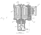
- FIG. 5 will illustrate how the separator 10 is incorporated into a twin tower air cleaning system as disclosed in the two co-pending patent applications cited above, namely Serial Nos. 08/597,261 and 08/597,262.
- the prior art twin tower air cleaning system was designed to clean and dry a stream of unpurified pressurized air received from a source of compressed air such as an air compressor so as to supply a pneumatic system with purified dry air.
- the unpurified compressed air from a conventional air compressor typically contain the vapor of various substances as well as moisture in the form of water or other liquids such as various oils.
- the terms vapor and moisture are herein collectively referred to as "moisture.”
- the unpurified air will also typically contain other particulates such as dirt, dust, pollen and various other contaminants.
- the new and improved twin tower air drying system of this invention includes a centrifugal separator 10 , as disclosed above, attached to the bottom side of the main structure body member 50, to which a pair of desiccant containing towers 52 and 54 are incorporated to extend vertically upward in an side-by-side relationship.
- the desiccant media is a particulate material and contained within a porous replaceable cartridge or bag.
- a pair of control valves 56 are also provided within body member 50 for switching the flow of compressed air into either one of the two towers 52 or 54.
- a shuttle valve mechanism 58 is provided on top of body member 50, which operates in cooperation with the two control valves 56, to control the flow of the cleaned dry compressed air emerging from the two towers 52 and 54, a portion of which is conveyed to the pneumatic system and a portion of which is used in the purge cycle.
- the moisture laden compressed air from the air compressor (not shown) is first passed into the inventive centrifugal separator 10 (as described above) which will eliminate a major portion of the moisture and particulate matter from the compressed air prior to its being further purified and dried in one of the twin tower 52 or 54.
- the compressed air from the air compressor is admitted into centrifugal separator 10 via inlet ports 26, substantially as described above.
- the compressed air is then significantly de-watered as described above and exits via air vent 28 were it is directed via one of the control valves 56 into the bottom of either tower 52 or 54, that is, which ever one is at that time functioning in the air drying cycle as controlled by the control valves 56.
- the compressed gas In passing upwardly through the desiccant within the tower (either 52 or 54) the compressed gas is further dried by the desiccant and emerges from the tower via the shuttle valve mechanism 58 for distribution in an output percentage to the pneumatic system and in a purge percentage back into the twin tower system.
- the purge percentage of the cleaned and dried air is used to purge one the twin towers 52 or 54 of moisture it has previously collected, that is, that desiccant containing tower which at that time is functioning in the purge cycle.
- a timer 60 is provided to automatically switch the opening and closing of the control valves 56 so that for a predetermined period of time the compressed air is routed through tower 52, while the dried purge air is routed through tower 54. Then after that predetermined time, control valves are switched so that the function of the two towers 52 and 54 are switched.
- centrifugal separators are known and used in a variety of different applications, all of which have features which could be incorporated into this invention if helpful.
- the baffle 30 could perhaps be provided in a variety of different forms. For example, for some applications it is possible that the apertures 34 could be varied or even eliminated, or perhaps even a screen material could be utilized as the baffle 30 in some applications.
Landscapes
- Chemical & Material Sciences (AREA)
- Chemical Kinetics & Catalysis (AREA)
- Engineering & Computer Science (AREA)
- Analytical Chemistry (AREA)
- General Chemical & Material Sciences (AREA)
- Oil, Petroleum & Natural Gas (AREA)
- Separating Particles In Gases By Inertia (AREA)
- Drying Of Gases (AREA)
- Cyclones (AREA)
Applications Claiming Priority (2)
| Application Number | Priority Date | Filing Date | Title |
|---|---|---|---|
| US978796 | 1997-11-26 | ||
| US08/978,796 US6071321A (en) | 1997-11-26 | 1997-11-26 | E-1 air dryer liquid separator with baffle |
Publications (1)
| Publication Number | Publication Date |
|---|---|
| EP0919271A1 true EP0919271A1 (de) | 1999-06-02 |
Family
ID=25526394
Family Applications (1)
| Application Number | Title | Priority Date | Filing Date |
|---|---|---|---|
| EP98113490A Withdrawn EP0919271A1 (de) | 1997-11-26 | 1998-07-20 | Fliehkraftabscheider mit Prallplatte |
Country Status (6)
| Country | Link |
|---|---|
| US (1) | US6071321A (de) |
| EP (1) | EP0919271A1 (de) |
| AU (1) | AU746298B2 (de) |
| BR (1) | BR9806479A (de) |
| CA (1) | CA2233399C (de) |
| ZA (1) | ZA986285B (de) |
Cited By (4)
| Publication number | Priority date | Publication date | Assignee | Title |
|---|---|---|---|---|
| EP1337313A4 (de) * | 2000-10-23 | 2005-01-26 | Henry B Lewin | Vorrichtung und verfahren zur behandlung von druckluft |
| WO2005099871A1 (de) * | 2004-04-15 | 2005-10-27 | Knorr-Bremse Systeme für Nutzfahrzeuge GmbH | Luftaufbereitungsanlage mit ölabscheider und druckluftversorgungsanlage |
| CN102218251A (zh) * | 2011-07-07 | 2011-10-19 | 张宏伟 | 直排式吸油雾装置 |
| CN113167236A (zh) * | 2018-12-13 | 2021-07-23 | 西门子歌美飒可再生能源公司 | 用于排出风力涡轮机中的湿气的装置 |
Families Citing this family (74)
| Publication number | Priority date | Publication date | Assignee | Title |
|---|---|---|---|---|
| US6440197B1 (en) | 1999-07-27 | 2002-08-27 | G.B.D. Corp. | Apparatus and method separating particles from a cyclonic fluid flow including an apertured particle separation member within a cyclonic flow region |
| US6221134B1 (en) * | 1999-07-27 | 2001-04-24 | G.B.D. Corp. | Apparatus and method for separating particles from a cyclonic fluid flow |
| US6228260B1 (en) | 1999-07-27 | 2001-05-08 | G. B. D. Corp. | Apparatus for separating particles from a cyclonic fluid flow |
| US6251296B1 (en) | 1999-07-27 | 2001-06-26 | G.B.D. Corp. | Apparatus and method for separating particles from a cyclonic fluid flow |
| US6231645B1 (en) | 1999-07-27 | 2001-05-15 | G.B.D. Corp. | Apparatus and method for separating particles from a cyclonic fluid flow utilizing a movable access member associated with a cyclonic separator |
| US6228151B1 (en) | 1999-08-18 | 2001-05-08 | G.B.D. Corp. | Apparatus and method for separating particles from a cyclonic fluid flow |
| US6358291B1 (en) * | 1999-09-17 | 2002-03-19 | James P. Koenig | Trailer air dryer with bypass valving and service indicator |
| US6753503B2 (en) * | 2002-07-08 | 2004-06-22 | Illinois Tool Works Inc. | Oil separator for a welder |
| US6797037B2 (en) | 2002-09-06 | 2004-09-28 | Waukesha Electric Systems, Incorporated | Dehydrating breather apparatus and method |
| US7332015B2 (en) * | 2002-09-06 | 2008-02-19 | Waukesha Electric Systems, Inc | Automatic dehydrating breather apparatus and method |
| US6730143B1 (en) * | 2002-11-18 | 2004-05-04 | Bendix Commercial Vehicle Systems, Llc | Truck air dryer purge air cleaner |
| SE526571C2 (sv) * | 2003-03-21 | 2005-10-11 | Haldex Brake Prod Ab | Lufttorkare försedd med en mellankassett |
| US7014690B2 (en) * | 2003-12-18 | 2006-03-21 | Westinghouse Air Brake Technologies Corporation | Expandable desiccant element |
| ITMI20032561A1 (it) * | 2003-12-22 | 2005-06-23 | Metal Work Spa | Dispositivo perfezionato per il filtraggio del flusso d'aria in impianti pneumatici |
| US20050235617A1 (en) * | 2004-04-23 | 2005-10-27 | Brian Read | Mist collector arrangement and methods |
| US20070266585A1 (en) * | 2005-04-16 | 2007-11-22 | Michael Arno | Portable Disposable Air/Gas Dryer |
| US20070209334A1 (en) * | 2006-03-10 | 2007-09-13 | Gbd Corp. | Vacuum cleaner with a removable screen |
| CA2599303A1 (en) | 2007-08-29 | 2009-02-28 | Gbd Corp. | Surface cleaning apparatus |
| US9192269B2 (en) | 2006-12-15 | 2015-11-24 | Omachron Intellectual Property Inc. | Surface cleaning apparatus |
| US11857142B2 (en) | 2006-12-15 | 2024-01-02 | Omachron Intellectual Property Inc. | Surface cleaning apparatus having an energy storage member and a charger for an energy storage member |
| US9888817B2 (en) | 2014-12-17 | 2018-02-13 | Omachron Intellectual Property Inc. | Surface cleaning apparatus |
| US20210401246A1 (en) | 2016-04-11 | 2021-12-30 | Omachron Intellectual Property Inc. | Surface cleaning apparatus |
| US10165912B2 (en) | 2006-12-15 | 2019-01-01 | Omachron Intellectual Property Inc. | Surface cleaning apparatus |
| BE1017715A3 (nl) * | 2007-08-29 | 2009-04-07 | Atlas Copco Airpower Nv | Vloeistofascheider. |
| US7708793B2 (en) * | 2007-08-29 | 2010-05-04 | Bendix Commercial Vehicle Systems Llc | Purge exhaust processor |
| US9265395B2 (en) | 2010-03-12 | 2016-02-23 | Omachron Intellectual Property Inc. | Surface cleaning apparatus |
| US12156626B2 (en) | 2009-03-13 | 2024-12-03 | Omachron Intellectual Property Inc. | Surface cleaning apparatus |
| US9433332B2 (en) | 2013-02-27 | 2016-09-06 | Omachron Intellectual Property Inc. | Surface cleaning apparatus |
| US9211044B2 (en) | 2011-03-04 | 2015-12-15 | Omachron Intellectual Property Inc. | Compact surface cleaning apparatus |
| US10722086B2 (en) | 2017-07-06 | 2020-07-28 | Omachron Intellectual Property Inc. | Handheld surface cleaning apparatus |
| DE102011109734A1 (de) * | 2011-08-08 | 2013-02-14 | Veritas Ag | Filterschutzkappe |
| US8999045B2 (en) | 2012-01-05 | 2015-04-07 | Suburban Manufacturing, Inc. | Regenerative air dryer |
| US9101856B2 (en) | 2012-06-01 | 2015-08-11 | Bendix Commercial Vehicle Systems Llc | Purge exhaust processor |
| US9320401B2 (en) | 2013-02-27 | 2016-04-26 | Omachron Intellectual Property Inc. | Surface cleaning apparatus |
| US9027198B2 (en) | 2013-02-27 | 2015-05-12 | G.B.D. Corp. | Surface cleaning apparatus |
| US9591958B2 (en) | 2013-02-27 | 2017-03-14 | Omachron Intellectual Property Inc. | Surface cleaning apparatus |
| US9427126B2 (en) | 2013-03-01 | 2016-08-30 | Omachron Intellectual Property Inc. | Surface cleaning apparatus |
| US9227151B2 (en) | 2013-02-28 | 2016-01-05 | Omachron Intellectual Property Inc. | Cyclone such as for use in a surface cleaning apparatus |
| US9451855B2 (en) | 2013-02-28 | 2016-09-27 | Omachron Intellectual Property Inc. | Surface cleaning apparatus |
| US9326652B2 (en) | 2013-02-28 | 2016-05-03 | Omachron Intellectual Property Inc. | Surface cleaning apparatus |
| US20140237764A1 (en) | 2013-02-28 | 2014-08-28 | G.B.D. Corp. | Cyclone such as for use in a surface cleaning apparatus |
| US9295995B2 (en) | 2013-02-28 | 2016-03-29 | Omachron Intellectual Property Inc. | Cyclone such as for use in a surface cleaning apparatus |
| US20140237768A1 (en) | 2013-02-28 | 2014-08-28 | G.B.D. Corp. | Surface cleaning apparatus |
| US9204773B2 (en) | 2013-03-01 | 2015-12-08 | Omachron Intellectual Property Inc. | Surface cleaning apparatus |
| US9161669B2 (en) | 2013-03-01 | 2015-10-20 | Omachron Intellectual Property Inc. | Surface cleaning apparatus |
| US9820621B2 (en) | 2013-02-28 | 2017-11-21 | Omachron Intellectual Property Inc. | Surface cleaning apparatus |
| US9238235B2 (en) | 2013-02-28 | 2016-01-19 | Omachron Intellectual Property Inc. | Cyclone such as for use in a surface cleaning apparatus |
| US9227201B2 (en) | 2013-02-28 | 2016-01-05 | Omachron Intellectual Property Inc. | Cyclone such as for use in a surface cleaning apparatus |
| US9314139B2 (en) | 2014-07-18 | 2016-04-19 | Omachron Intellectual Property Inc. | Portable surface cleaning apparatus |
| US9451853B2 (en) | 2014-07-18 | 2016-09-27 | Omachron Intellectual Property Inc. | Portable surface cleaning apparatus |
| US9585530B2 (en) | 2014-07-18 | 2017-03-07 | Omachron Intellectual Property Inc. | Portable surface cleaning apparatus |
| US9420925B2 (en) | 2014-07-18 | 2016-08-23 | Omachron Intellectual Property Inc. | Portable surface cleaning apparatus |
| US11950745B2 (en) | 2014-12-17 | 2024-04-09 | Omachron Intellectual Property Inc. | Surface cleaning apparatus |
| US10136778B2 (en) | 2014-12-17 | 2018-11-27 | Omachron Intellectual Property Inc. | Surface cleaning apparatus |
| US10251519B2 (en) | 2014-12-17 | 2019-04-09 | Omachron Intellectual Property Inc. | Surface cleaning apparatus |
| WO2017184855A1 (en) * | 2016-04-20 | 2017-10-26 | Carleton Life Support Systems, Inc. | Moisture resistant molecular sieve beds |
| US11730327B2 (en) | 2020-03-18 | 2023-08-22 | Omachron Intellectual Property Inc. | Surface cleaning apparatus with removable air treatment assembly |
| US10537216B2 (en) | 2017-07-06 | 2020-01-21 | Omachron Intellectual Property Inc. | Handheld surface cleaning apparatus |
| US10702113B2 (en) | 2017-07-06 | 2020-07-07 | Omachron Intellectual Property Inc. | Handheld surface cleaning apparatus |
| US11445878B2 (en) | 2020-03-18 | 2022-09-20 | Omachron Intellectual Property Inc. | Surface cleaning apparatus with removable air treatment member assembly |
| US11666193B2 (en) | 2020-03-18 | 2023-06-06 | Omachron Intellectual Property Inc. | Surface cleaning apparatus with removable air treatment member assembly |
| US10631693B2 (en) | 2017-07-06 | 2020-04-28 | Omachron Intellectual Property Inc. | Handheld surface cleaning apparatus |
| US10750913B2 (en) | 2017-07-06 | 2020-08-25 | Omachron Intellectual Property Inc. | Handheld surface cleaning apparatus |
| US10506904B2 (en) | 2017-07-06 | 2019-12-17 | Omachron Intellectual Property Inc. | Handheld surface cleaning apparatus |
| US11766156B2 (en) | 2020-03-18 | 2023-09-26 | Omachron Intellectual Property Inc. | Surface cleaning apparatus with removable air treatment member assembly |
| US10842330B2 (en) | 2017-07-06 | 2020-11-24 | Omachron Intellectual Property Inc. | Handheld surface cleaning apparatus |
| US11930987B2 (en) | 2018-04-20 | 2024-03-19 | Omachron Intellectual Property Inc. | Surface cleaning apparatus |
| US11013384B2 (en) | 2018-08-13 | 2021-05-25 | Omachron Intellectual Property Inc. | Cyclonic air treatment member and surface cleaning apparatus including the same |
| US11192122B2 (en) | 2018-08-13 | 2021-12-07 | Omachron Intellectual Property Inc. | Cyclonic air treatment member and surface cleaning apparatus including the same |
| US11006799B2 (en) | 2018-08-13 | 2021-05-18 | Omachron Intellectual Property Inc. | Cyclonic air treatment member and surface cleaning apparatus including the same |
| CN110856786A (zh) * | 2018-08-23 | 2020-03-03 | 金索股份有限公司 | 旋风集尘的干式化学吸附处理装置 |
| US20210386258A1 (en) | 2020-03-18 | 2021-12-16 | Omachron Intellectual Property Inc. | Surface cleaning apparatus |
| BE1028303B1 (nl) * | 2020-05-13 | 2021-12-16 | Atlas Copco Airpower Nv | Inrichting en werkwijze voor het adsorberen van een gas uit een te behandelen gasmengsel |
| CN119394716A (zh) * | 2024-10-25 | 2025-02-07 | 中国核电工程有限公司 | 一种放射性料液取样容器以及取样系统 |
Citations (8)
| Publication number | Priority date | Publication date | Assignee | Title |
|---|---|---|---|---|
| US3481118A (en) * | 1968-04-22 | 1969-12-02 | Porta Test Mfg | Cyclone separator |
| US3753336A (en) * | 1972-04-06 | 1973-08-21 | Envirotech Corp | Centrifugal separation apparatus |
| US4018579A (en) * | 1974-04-20 | 1977-04-19 | Durr - Dental Kg | Apparatus for producing dry compressed air |
| WO1981001961A1 (fr) * | 1980-01-14 | 1981-07-23 | M Geissmann | Procede et separateur pour isoler un liquide d'un melange gaz-liquide |
| US4459141A (en) * | 1983-01-03 | 1984-07-10 | Medalie Manufacturing Company | Air cleaning device |
| EP0195464A1 (de) * | 1985-03-05 | 1986-09-24 | Shell Internationale Researchmaatschappij B.V. | Kolonne zur Entfernung einer Flüssigkeit aus einem Gas |
| FR2584944A1 (fr) * | 1985-07-17 | 1987-01-23 | Gaz De France | Procede de separation mecanique d'un fluide diphasique et dispositif comportant application de ce procede |
| WO1994027706A1 (en) * | 1993-05-26 | 1994-12-08 | A.P. Systems (Australia) Pty. Ltd. | Air drying and purification system |
Family Cites Families (5)
| Publication number | Priority date | Publication date | Assignee | Title |
|---|---|---|---|---|
| US2943698A (en) * | 1960-07-05 | Cyclone-type separator | ||
| US3483677A (en) * | 1967-02-06 | 1969-12-16 | Herbert Pinto | Air cleaning device |
| US3877904A (en) * | 1974-06-18 | 1975-04-15 | Combustion Eng | Gas-liquid separator |
| JPS5410598Y2 (de) * | 1974-10-31 | 1979-05-16 | ||
| US4853010A (en) * | 1984-09-12 | 1989-08-01 | Spence Billy F | Multi stage gas scrubber |
-
1997
- 1997-11-26 US US08/978,796 patent/US6071321A/en not_active Expired - Fee Related
-
1998
- 1998-03-26 CA CA002233399A patent/CA2233399C/en not_active Expired - Fee Related
- 1998-07-15 ZA ZA986285A patent/ZA986285B/xx unknown
- 1998-07-20 EP EP98113490A patent/EP0919271A1/de not_active Withdrawn
- 1998-08-11 BR BR9806479-7A patent/BR9806479A/pt not_active Application Discontinuation
- 1998-08-12 AU AU79906/98A patent/AU746298B2/en not_active Ceased
Patent Citations (8)
| Publication number | Priority date | Publication date | Assignee | Title |
|---|---|---|---|---|
| US3481118A (en) * | 1968-04-22 | 1969-12-02 | Porta Test Mfg | Cyclone separator |
| US3753336A (en) * | 1972-04-06 | 1973-08-21 | Envirotech Corp | Centrifugal separation apparatus |
| US4018579A (en) * | 1974-04-20 | 1977-04-19 | Durr - Dental Kg | Apparatus for producing dry compressed air |
| WO1981001961A1 (fr) * | 1980-01-14 | 1981-07-23 | M Geissmann | Procede et separateur pour isoler un liquide d'un melange gaz-liquide |
| US4459141A (en) * | 1983-01-03 | 1984-07-10 | Medalie Manufacturing Company | Air cleaning device |
| EP0195464A1 (de) * | 1985-03-05 | 1986-09-24 | Shell Internationale Researchmaatschappij B.V. | Kolonne zur Entfernung einer Flüssigkeit aus einem Gas |
| FR2584944A1 (fr) * | 1985-07-17 | 1987-01-23 | Gaz De France | Procede de separation mecanique d'un fluide diphasique et dispositif comportant application de ce procede |
| WO1994027706A1 (en) * | 1993-05-26 | 1994-12-08 | A.P. Systems (Australia) Pty. Ltd. | Air drying and purification system |
Cited By (9)
| Publication number | Priority date | Publication date | Assignee | Title |
|---|---|---|---|---|
| EP1337313A4 (de) * | 2000-10-23 | 2005-01-26 | Henry B Lewin | Vorrichtung und verfahren zur behandlung von druckluft |
| US7014691B2 (en) | 2000-10-23 | 2006-03-21 | Lewin Henry B | Apparatus and method for treating compressed air |
| WO2005099871A1 (de) * | 2004-04-15 | 2005-10-27 | Knorr-Bremse Systeme für Nutzfahrzeuge GmbH | Luftaufbereitungsanlage mit ölabscheider und druckluftversorgungsanlage |
| KR100988331B1 (ko) * | 2004-04-15 | 2010-10-18 | 크노르-브렘제 시스테메 퓌어 누츠파조이게 게엠베하 | 오일 분리기를 구비한 공기 정화 유닛 및 압축 공기 공급유닛 |
| CN102218251A (zh) * | 2011-07-07 | 2011-10-19 | 张宏伟 | 直排式吸油雾装置 |
| CN102218251B (zh) * | 2011-07-07 | 2013-06-12 | 张宏伟 | 直排式吸油雾装置 |
| CN113167236A (zh) * | 2018-12-13 | 2021-07-23 | 西门子歌美飒可再生能源公司 | 用于排出风力涡轮机中的湿气的装置 |
| US20220025868A1 (en) * | 2018-12-13 | 2022-01-27 | Siemens Gamesa Renewable Energy A/S | Device for draining humidity in wind turbines |
| US11629702B2 (en) * | 2018-12-13 | 2023-04-18 | Siemens Gamesa Renewable Energy A/S | Device for draining humidity in wind turbines |
Also Published As
| Publication number | Publication date |
|---|---|
| CA2233399A1 (en) | 1999-05-26 |
| CA2233399C (en) | 2001-05-29 |
| BR9806479A (pt) | 1999-12-14 |
| AU7990698A (en) | 1999-06-17 |
| US6071321A (en) | 2000-06-06 |
| AU746298B2 (en) | 2002-04-18 |
| ZA986285B (en) | 1999-02-04 |
Similar Documents
| Publication | Publication Date | Title |
|---|---|---|
| US6071321A (en) | E-1 air dryer liquid separator with baffle | |
| CA2233287C (en) | E-1 twin tower air dryer for an air compressor unit | |
| JP3231718B2 (ja) | 圧縮空気清浄/乾燥装置用のシャトル弁機構 | |
| US3464186A (en) | Dryer for compressed fluid systems | |
| EP0933118B1 (de) | Doppelturmlufttrockner | |
| US3572008A (en) | Methods and means for cleaning and drying compressed fluid systems | |
| US11655865B2 (en) | Separating device and use of the device for separating and collecting brake dust | |
| US5866000A (en) | Apparatus for separating dispersed liquid from a continuous fluid | |
| JPH09206544A (ja) | 二塔式ガス乾燥システム | |
| US5930910A (en) | Purge tube with flapper valve for desiccant containing air drier | |
| US5037454A (en) | Coalescing apparatus and method | |
| JP2021522989A (ja) | 車両空気ブレーキ充填システム用の放出物処理装置 | |
| JPH09206545A (ja) | 二塔式ガス乾燥システム用の逆止弁機構 | |
| JP3061609B2 (ja) | 2方向制御弁構造 | |
| KR890004043Y1 (ko) | 분진제거 및 탈취장치 | |
| KR100558215B1 (ko) | 필터를 이용한 집적공기건조장치 | |
| RU2009698C1 (ru) | Коалесцентный фильтр-осушитель | |
| SU1039533A1 (ru) | Центробежно-мокрый пылеуловитель |
Legal Events
| Date | Code | Title | Description |
|---|---|---|---|
| PUAI | Public reference made under article 153(3) epc to a published international application that has entered the european phase |
Free format text: ORIGINAL CODE: 0009012 |
|
| AK | Designated contracting states |
Kind code of ref document: A1 Designated state(s): DE FR GB IT |
|
| AX | Request for extension of the european patent |
Free format text: AL;LT;LV;MK;RO;SI |
|
| 17P | Request for examination filed |
Effective date: 19991126 |
|
| AKX | Designation fees paid |
Free format text: DE FR GB IT |
|
| 17Q | First examination report despatched |
Effective date: 20000321 |
|
| GRAP | Despatch of communication of intention to grant a patent |
Free format text: ORIGINAL CODE: EPIDOSNIGR1 |
|
| GRAP | Despatch of communication of intention to grant a patent |
Free format text: ORIGINAL CODE: EPIDOSNIGR1 |
|
| GRAS | Grant fee paid |
Free format text: ORIGINAL CODE: EPIDOSNIGR3 |
|
| STAA | Information on the status of an ep patent application or granted ep patent |
Free format text: STATUS: THE APPLICATION IS DEEMED TO BE WITHDRAWN |
|
| 18D | Application deemed to be withdrawn |
Effective date: 20050201 |