EP0919177B1 - Dispositif pour sècher des aliments - Google Patents
Dispositif pour sècher des aliments Download PDFInfo
- Publication number
- EP0919177B1 EP0919177B1 EP98111743A EP98111743A EP0919177B1 EP 0919177 B1 EP0919177 B1 EP 0919177B1 EP 98111743 A EP98111743 A EP 98111743A EP 98111743 A EP98111743 A EP 98111743A EP 0919177 B1 EP0919177 B1 EP 0919177B1
- Authority
- EP
- European Patent Office
- Prior art keywords
- basket
- handle structure
- bowl
- lid
- drive assembly
- Prior art date
- Legal status (The legal status is an assumption and is not a legal conclusion. Google has not performed a legal analysis and makes no representation as to the accuracy of the status listed.)
- Expired - Lifetime
Links
Images


Classifications
-
- A—HUMAN NECESSITIES
- A47—FURNITURE; DOMESTIC ARTICLES OR APPLIANCES; COFFEE MILLS; SPICE MILLS; SUCTION CLEANERS IN GENERAL
- A47J—KITCHEN EQUIPMENT; COFFEE MILLS; SPICE MILLS; APPARATUS FOR MAKING BEVERAGES
- A47J43/00—Implements for preparing or holding food, not provided for in other groups of this subclass
- A47J43/24—Devices for washing vegetables or the like
Definitions
- This invention relates to devices for drying wet food, such as salad spinners.
- salad spinners Various devices for drying food, such as salad spinners, are known. These salad spinners usually include a bowl, a cover connected to the bowl, a perforated basket, and a crank-type actuator coupled to the basket for spinning the same. These prior spinners, however, are not always stable when cranked, often moving laterally during the cranking operation, which can cause the spinner to fall off its support to the floor. These falls may cause the spinner to be damaged or food contents thereof to be spilled. To safely use the spinner, a user must often hold down the spinner with one hand and crank with the other hand.
- crank mechanisms of these spinners have a knob or other portion permanently disposed on and projecting laterally from the top of the cover. These projecting knobs can be damaged and take up space when not in use, making storage difficult.
- a device for drying foods according to the preamble of claim 1 is known from CH-A-351 731.
- An important feature of the invention is the provision of a device having a pumping actuator to rotate a basket relative to a bowl, which requires little force to operate and minimizes fatigue in use.
- a further feature of the invention is the provision of device of the type set forth which can be used with ease and convenience.
- a further feature of the invention is the provision of device of the type set forth, which can be operated with one hand while the bowl remains stationary in use.
- a device for drying food according to the preamble of claim 1, which includes a bowl having a bottom wall and a sidewall terminating in a top edge, a cover removably connected to the top edge of the bowl, a perforated basket disposed in the bowl and rotatable about an axis and a drive assembly carried by the cover and coupled to the basket for effecting rotation thereof.
- the drive assembly includes a linearly reciprocating handle structure and a conversion mechanism for converting reciprocating movement of the handle structure to rotary motion of the basket.
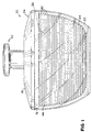
- the salad spinner 20 generally includes a bowl 22, a cover 24 for the bowl 22, a perforated basket 26 disposed in the bowl 22, a lid 28 for the basket 26 and a drive assembly 30 for rotating the perforated basket 26.
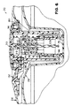
- the bowl 22 is circular in shape and, as seen in FIG. 3, has a central vertical axis A and a bottom wall 32 having a cone-shaped projection 34 in its center.
- the bowl 22 also includes a sidewall 36 terminating in a top edge 38 and a foot 40 connected to the bottom wall 32 and preferably made of a non-slip material.
- the basket 26, as best seen in FIGS. 3 and 8, includes a plurality of latitudinal, coaxial circular ribs 42 connected by a plurality of longitudinal ribs 44 of various lengths.
- the ribs 42 and 44 cooperate to define a plurality of various sized, generally rectangular apertures 46.
- the basket 26, as seen in FIG. 3, also includes a bottom 48 having a cone-shaped projection 50 at its center which sits atop cone-shaped projection 34 to form a rotational bearing.
- the ribs 42 and 44 together form a sidewall 52 terminating at an upper edge 54.
- the lid 28, as best seen in FIGS. 3, 9, and 10 includes a cylindrical peripheral sidewall 56 having a plurality of ribs 58 projecting outwardly therefrom. Referring to FIG. 3, diametrically opposed pairs of the ribs 58 cooperate to provide a friction fit with the upper edge 54 of the basket 26.
- the lid 28 includes a convex annular surface portion 60 connected to the circular sidewall 56, a frustoconical shaped central portion 62 depending from the annular surface portion 60, a radially inwardly extending bottom surface portion 64 (FIG. 16) integral with the lower end of the frustoconical shaped surface portion 62 and a tubular, upwardly projecting portion 66 integral and coaxial with the bottom surface portion 64.
- the upwardly projecting portion 66 varies in diameter and has shoulder surfaces 68, 70 formed thereon.
- the upwardly projecting portion 66 also includes a slot 71 disposed above shoulder surface 70 (FIG. 5). Referring to FIG.
- the upwardly projecting portion 66 has a terminal open end 72 having four inclined arcuate surfaces 73 and four axially extending engaging portions 74 forming, as discussed below, a portion of drive assembly 30.
- a plug 75 closes the lower end of the upwardly projecting portion 66 to prevent food from entering the interior thereof.
- the cover 24 includes a cylindrical sidewall 76 having an outer diameter substantially equal to the inner diameter of the top edge 38 of the bowl 22 thereby forming a friction fit therebetween.
- the cover 24 also has an upper surface portion 78, a depending, substantially cylindrical central surface portion 80, an annular bottom surface portion 82 and a generally cylindrical upwardly projecting portion 84 disposable coaxially about a portion of the upwardly projecting portion 66 of the lid 28.
- the upwardly projecting portion 84 has a radially inturned end 86 at its upper end which abuts shoulder surface 68 of upwardly projecting portion 66.
- the upwardly projecting portion 84 has a plurality of axial ribs 88 projecting radially outwardly therefrom. The upper ends of ribs 88 and portions 90 of the end 86 form a generally annular groove 91 therebetween.
- the cylindrical surface portion 80 includes two vertical slots 92 disposed about 180 degrees apart and running the majority of the length of the cylindrical surface portion 80.
- the drive assembly 30 includes a linearly reciprocating handle structure 94 (or plunger assembly) moveable along vertical axis A.
- the reciprocating handle structure 94 includes a disc shaped upper end 96, or button structure, and a coaxial cylindrical sidewall 98 depending therefrom.
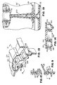
- the cylindrical sidewall 98 has a slot 99 adjacent to its upper end and, referring to FIG. 4, two radially outwardly extending projections 100 at its lower end, each forming a shoulder surface 102.
- the projections 100 are respectively disposed in the vertical slots 92 of the cylindrical surface portion 80 of the cover 24 for limiting upward axial movement and preventing rotation of the reciprocating handle structure 94 relative to the cover 24.
- the drive assembly 30 also includes a conversion mechanism 104 for converting the reciprocating movement of the handle structure 94 to rotary motion of the basket 26.
- the conversion mechanism 104 includes an elongated helical screw shaft 106 coaxial with the handle structure 94 and connected at one end to the disc shaped upper end 96, preferably by a pin 107 (FIG. 4).
- the elongated helical shaft 106 extends a slight distance below the lower end of the cylindrical sidewall 98.
- the conversion mechanism 104 also includes a nut 108 having a slot 110 shaped to receive the helical shaft 106 therethrough for screw-type engagement therewith.
- the slot 110 is formed by two identical opposing spaced-apart faces 150, 151.
- Each face 150, 151 includes four quadrants 152A-D.
- Quadrants 152A and 152D are diagonally opposed and generally co-planar.
- Quadrants 152B and 152C are diagonally opposed and slope away from the same side of the plane of quadrants 152A and 152D.
- Quadrants 152A, 152B, 152C, 152D of face 150 respectively face quadrants 152B, 152A, 152D, 152C of face 151.
- the nut 108 also includes a tubular lower end 111 and a disc shaped upper portion 112 having a plurality of projections 114 depending therefrom.
- Each projection 114 includes an inclined arcuate surface 116 and an engaging portion 118.
- the conversion mechanism 104 also includes the engaging portions 74 of upwardly projecting portion 66 of the basket lid 28.
- the drive assembly 30 also includes a cap 120 having a top wall 122 and a substantially cylindrical sidewall 124.
- the substantially cylindrical sidewall 124 includes a radially inwardly extending projection 126 at its bottom end.
- the cap 120 is disposed about the terminal end 72 of the upwardly projecting portion 66 of the lid 28 above shoulder surface 70 and the projection 126 is disposed in slot 71 to maintain the cap 120 attached to upwardly projecting portion 66.
- the cap 120 limits the axial movement of the nut 108.
- the drive assembly 30 also includes a helical compression spring 128 seated in groove 91 of the upwardly projecting portion 84 and against the disc shaped upper portion 96 of the reciprocating handle structure 94.
- FIGS. 3 and 4 illustrate the conversion mechanism 104 in a non-engaged normal rest condition where, as seen in FIG. 4, the engaging portions 118 of the nut 108 are spaced apart axially from the engaging portions 74 of the lid 28.
- the spring 128 biases the drive assembly 30 to this condition.
- the spring 128 causes the reciprocating handle structure 94, the helical shaft 106 and the nut 108 to initially move axially upwardly together until the nut 108 contacts the top wall 122 of the cap 120 to stop further axial movement of the nut 108.
- the conversion mecnanism 104 is now in its disengaged condition.
- the helical shaft 106 and the reciprocating handle structure 94 continue to move axially upward back to the position shown in FIG. 4.
- the helical shaft 106 moves through the slot 110 of nut 108 causing it to rotate.
- Repeated plunging motions may be applied, as necessary, to rotate the basket 26 in which wet or washed food is placed.
- the rotation of the perforated basket 26 causes the liquid on the food to be sent out of the perforated basket 26 through apertures 46 by centrifugal force into the bowl 22, thereby drying the food in the basket.
- the ribs 44 of the perforated basket 26 and the ribs 58 of the lid 28 cooperate to ensure that the basket 26 rotates when the reciprocating handle structure 94 is plunged down. As seen in FIGS. 9 and 10, when the lid 28 is rotated, each rib 58 thereof can contact a rib 44 to rotate the perforated basket 26.
- the salad spinner 20 also includes a stop mechanism 130 to prevent axial movement of the reciprocating handle structure 94.
- the stop mechanism 130 includes the slot 99 of the cylindrical sidewall 98 and a latch 132 supported by the cover 24.
- the latch 132 includes a central portion 134 terminating in a rectangular projection 136 and two laterally projecting legs 138 each, having a raised surface portion 140. As seen in FIGS. 6 and 12, when it is desired to prevent axial movement of the reciprocating handle structure 94, the handle structure 94 is fully depressed and the latch 132 is slid so that the projection 136 is placed in slot 99 of the reciprocating handle structure 94.
- the cover 24 includes two flexible walls 142 depending from the interior surface of the cover 24.
- the latch 132 is supported by the cover so that at least a portion of the raised surface portion 140 extends above the bottom of the flexible wall 142 which prevents the box-like projection 136 of latch 132 from accidentally moving out of (or into) the slot 99 without a force being applied to the latch 132 to cause the raised surface portions 140 to flex the flexible wall 142 to allow movement of the latch 132 under the flexible wall 142.
- FIG. 19 illustrates a salad spinner 20' having an alternative basket embodiment.
- the spinner 20' is identical to spinner 20 of FIGS. 1-16 except that a post 200 is provided in the basket 26.
- the post 200 projects upwardly from the center of the perforated basket 26 and contacts the plug 75.
- the post 200 transfers vertical forces or load onto the center of the bowl 22 rather than through the lid 28 and perforated basket 26 which may cause them to flex, be damaged and cause the basket to flex causing components to interfere with each other to inhibit free rotation.
- the conversion mechanism of the drive assembly could include a gearing system wherein the linear reciprocating handle structure (or plunger assembly) may include a shaft having a vertically disposed gear rack.
- the gearing system would also include an annular gear rack disposed on or coupled to the lid 28 (and basket 26) and an intermediary primary gear coupling the vertical gear rack to the annular gear rack.
- the vertical gear rack engages the primary gear, which in turn engages the circular rack to rotate the lid and basket coupled thereto.
Claims (13)
- Dispositif (20) destiné au séchage d'aliments comprenant :caractérisé en ce queun bol (22) comportant une paroi inférieure (32) ainsi qu'une paroi latérale (36) se terminant par un bord supérieur (38) ;un panier perforé (26) disposé dans le bol (22) et pouvant être entraíné en rotation autour d'un axe ;un ensemble d'entraínement (30) relié au panier (26) afin de provoquer une rotation de celui-ci, l'ensemble d'entraínement (39) comprenant une structure de poignée à mouvement alternatif linéaire (94) pouvant être déplacée entre une position relevée et une position abaissée, ainsi qu'un mécanisme de conversion (104) destiné à convertir le mouvement alternatif de la structure de poignée (94) en un mouvement rotatif du panier ; etun couvercle (28) relié de façon amovible au panier (26) et pouvant être mis en prise avec la structure de poignée (94) de façon qu'un déplacement de la structure de poignée (94) par rapport au couvercle (28) entre les positions relevée et abaissée provoque une rotation du couvercle (28) et du panier (26) ;une protection (24) est fixée de façon amovible au bord supérieur (38) du bol ;l'ensemble d'entraínement (30) est supporté par la protection (24) ; etune structure de sollicitation (128) est prévue afin de solliciter la poignée (94) en direction de la position relevée.
- Dispositif selon la revendication 1, dans lequel la structure de sollicitation (128) est disposée entre la protection (24) et la structure de poignée (94).
- Dispositif selon la revendication 2, dans lequel la structure de sollicitation (128) comprend un ressort (128).
- Dispositif selon la revendication 1, dans lequel le mécanisme de conversion (104) comprend une tige hélicoïdale (106) reliée à la structure de poignée (94), un écrou (108) comportant une fente (110) dans laquelle passe la tige (106) et pouvant être mis en prise avec le couvercle (28), dans lequel lorsque la structure de poignée (94) est déplacée suivant une direction depuis la position relevée vers la position abaissée, la tige hélicoïdale (106) passe à travers la fente (110) afin de faire tourner l'écrou (108) et le couvercle (28).
- Dispositif selon la revendication 4, dans lequel la structure de poignée à mouvement alternatif (94) comprend une paroi latérale cylindrique (98) coaxiale à la tige (106) ainsi qu'une paroi supérieure (96) refermant la paroi latérale cylindrique (98) à une extrémité de celle-ci et reliée à la tige hélicoïdale (106).
- Dispositif selon la revendication 1, et comprenant en outre un mécanisme d'arrêt (130) destiné à empêcher le déplacement de la structure de poignée à mouvement alternatif (94) entre les positions relevée et abaissée.
- Dispositif selon la revendication 6, dans lequel le mécanisme d'arrêt (130) maintient de façon débroyable la structure de poignée (94) dans la position abaissée.
- Dispositif selon la revendication 1, dans lequel la structure de poignée (94) peut être déplacée le long de l'axe.
- Dispositif selon la revendication 1, dans lequel le panier perforé (26) comporte une paroi inférieure (48) ainsi qu'une paroi latérale (52) se terminant au niveau d'un bord supérieur (54), et dans lequel l'ensemble de commande (30) est espacé de la paroi inférieure du panier (26).
- Dispositif selon la revendication 1, dans lequel le panier perforé (26) comporte une paroi inférieure (48) ainsi qu'une paroi latérale (52) se terminant au niveau d'un bord supérieur (54), et est exempt de structure dans une région de stockage délimitée par la paroi latérale (52) et la paroi inférieure (48) du panier et un plan perpendiculaire à l'axe et espacé bien au-dessus de la paroi inférieure (48) du panier (26).
- Dispositif selon la revendication 1, dans lequel l'ensemble d'entraínement (30) est supporté uniquement par la protection (24).
- Dispositif selon la revendication 11, dans lequel le bord supérieur (38) du bol (22) définit une ouverture présentant une superficie, la protection (24) s'étendant pratiquement sur la superficie entière de l'ouverture du bol (22).
- Dispositif selon la revendication 12, dans lequel le bord supérieur (54) du panier (26) définit une ouverture présentant une superficie, le couvercle (28) s'étendant pratiquement sur la superficie entière de l'ouverture du panier (26) .
Priority Applications (1)
| Application Number | Priority Date | Filing Date | Title |
|---|---|---|---|
| DK98111743T DK0919177T3 (da) | 1997-11-26 | 1998-06-25 | Apparat til tørring af fødevarer |
Applications Claiming Priority (2)
| Application Number | Priority Date | Filing Date | Title |
|---|---|---|---|
| US980000 | 1997-11-26 | ||
| US08/980,000 US5992309A (en) | 1997-11-26 | 1997-11-26 | Device for drying foods |
Publications (2)
| Publication Number | Publication Date |
|---|---|
| EP0919177A1 EP0919177A1 (fr) | 1999-06-02 |
| EP0919177B1 true EP0919177B1 (fr) | 2000-03-22 |
Family
ID=25527283
Family Applications (1)
| Application Number | Title | Priority Date | Filing Date |
|---|---|---|---|
| EP98111743A Expired - Lifetime EP0919177B1 (fr) | 1997-11-26 | 1998-06-25 | Dispositif pour sècher des aliments |
Country Status (12)
| Country | Link |
|---|---|
| US (1) | US5992309A (fr) |
| EP (1) | EP0919177B1 (fr) |
| CN (1) | CN1144562C (fr) |
| AT (1) | ATE190816T1 (fr) |
| AU (1) | AU707105B1 (fr) |
| CA (1) | CA2242796C (fr) |
| DE (2) | DE69800100T2 (fr) |
| DK (1) | DK0919177T3 (fr) |
| ES (1) | ES2147467T3 (fr) |
| GR (1) | GR3033753T3 (fr) |
| PT (1) | PT919177E (fr) |
| TW (1) | TW431875B (fr) |
Families Citing this family (33)
| Publication number | Priority date | Publication date | Assignee | Title |
|---|---|---|---|---|
| US6473988B1 (en) * | 2001-08-17 | 2002-11-05 | Wki Holding Company, Inc. | Auxiliary container for salad spinner |
| AU2002313439A1 (en) * | 2001-11-19 | 2003-06-10 | Moha Moderne Haushaltwaren Ag | Salad shaker |
| US6622618B1 (en) | 2002-06-14 | 2003-09-23 | Bojour, Inc. | Salad spinner |
| US6510785B1 (en) * | 2002-07-03 | 2003-01-28 | Mr. Bar-B-Q, Inc. | Hand operated centrifugal dryer |
| FR2854878B1 (fr) | 2003-05-15 | 2006-03-31 | Valois Sas | Distributeur de produit fluide. |
| US7111546B2 (en) * | 2004-03-19 | 2006-09-26 | Lifetime Brands, Inc. | Salad spinner with improved drive assembly |
| DE202004016636U1 (de) | 2004-07-21 | 2004-12-16 | Moha Moderne Haushaltwaren Ag | Salatschleuder |
| US7448315B2 (en) * | 2005-03-17 | 2008-11-11 | Helen Of Troy Limited | Food drying device with separable lid and cover |
| US20060260366A1 (en) * | 2005-05-18 | 2006-11-23 | I+Dcreative, Llc | Laundry appliance for washing small quantities of clothing |
| US20070006742A1 (en) * | 2005-06-16 | 2007-01-11 | Design For Living, L.L.C. | Food spinner with suction device and brake |
| US7946752B2 (en) | 2005-09-06 | 2011-05-24 | Sharron Swartz | Mug with stirring mechanism |
| US20070137504A1 (en) * | 2005-12-19 | 2007-06-21 | Kwok Kuen So | Salad spinner |
| US7681495B2 (en) * | 2005-12-19 | 2010-03-23 | Kwog Kuen So | Food processing device |
| US7958650B2 (en) * | 2006-01-23 | 2011-06-14 | Turatti S.R.L. | Apparatus for drying foodstuffs |
| US20080271239A1 (en) * | 2006-11-20 | 2008-11-06 | Qian Wang | Multi-function sink with centrifugal food dryer and drain |
| ATE483387T1 (de) * | 2007-02-07 | 2010-10-15 | Dalla Piazza & Co | Manueller zentrifugalantrieb mit schwenkhebelwirkung |
| US20090114104A1 (en) * | 2007-11-02 | 2009-05-07 | Ravi Kumar Sawhney | Drying Device With Improved Drive Mechanism |
| US7861647B2 (en) * | 2008-02-01 | 2011-01-04 | Kwok Kuen So | Kitchen utensil with a suction base mechanism |
| US20100083847A1 (en) * | 2008-10-06 | 2010-04-08 | Phillip Kirschbaum | Salad Spinning Assembly |
| DE102009016205B4 (de) * | 2009-04-03 | 2011-06-22 | Leifheit AG, 56377 | Als Zerkleinerungsvorrichtung für Lebensmittel, Rührvorrichtung oder Schleudervorrichtung ausgebildete Vorrichtung |
| US20100263492A1 (en) * | 2009-04-17 | 2010-10-21 | Mah Pat Y | Bottle opening and closing device |
| US8539693B2 (en) | 2011-03-28 | 2013-09-24 | Helen Of Troy Limited | Brake mechanism for a device for drying foods and other items |
| HK1169778A2 (en) | 2012-01-13 | 2013-02-01 | Golden Choice Products Ltd | Food-drying device and related drive mechanism |
| US9080803B2 (en) | 2012-02-10 | 2015-07-14 | Turbo Innovations, Llc | Method and device for rapidly cooling liquids |
| GB2504453A (en) * | 2012-05-30 | 2014-02-05 | Carlo Chiarella | Reducing fat content by spinning a food product in a perforated container |
| TW201336583A (zh) * | 2013-03-05 | 2013-09-16 | Qiao-Fu Yang | 按壓式攪拌容器結構 |
| USD735250S1 (en) | 2013-06-11 | 2015-07-28 | Turbo Innovations, Llc | Rapid fluid heat exchange device |
| USD757500S1 (en) | 2014-09-10 | 2016-05-31 | Progressive International Corporation | Salad spinner bowl with base |
| US10016095B2 (en) | 2014-10-03 | 2018-07-10 | Progressive International Corporation | Salad spinner |
| CN106136784A (zh) * | 2015-04-22 | 2016-11-23 | 陈庆龙 | 助嚼器 |
| CN105839369A (zh) * | 2016-03-30 | 2016-08-10 | 李宏江 | 一种新式节能工业干衣机 |
| US20220202256A1 (en) | 2019-06-03 | 2022-06-30 | Carsten Bohn | A spinning device for drying foods |
| ES1261820Y (es) * | 2020-12-14 | 2021-05-28 | European Home Shopping S L | Accesorio de cocina multifunción |
Family Cites Families (28)
| Publication number | Priority date | Publication date | Assignee | Title |
|---|---|---|---|---|
| FR743906A (fr) * | 1933-04-08 | |||
| GB405485A (en) * | 1932-04-08 | 1934-02-08 | Friedrich Emil Krauss | Improvements in and relating to centrifugal machines, more particularly for household purposes |
| CH353509A (de) * | 1956-10-11 | 1961-04-15 | Singer Meyer Maria | Gerät zur Entwässerung von Gemüse, Früchten und dergleichen |
| CH351731A (fr) * | 1959-06-10 | 1961-01-31 | Bron Yvonne | Appareil à égoutter les légumes |
| FR1259498A (fr) * | 1960-03-16 | 1961-04-28 | Panier essoreur perfectionné | |
| US3587692A (en) * | 1969-06-25 | 1971-06-28 | New Nel Kitchens Products Co | Vegetable shredder |
| US3612532A (en) * | 1970-04-13 | 1971-10-12 | Ned Strongin | Apparatus having a cover continually decreasing the degree of accessability of a target |
| FR2123603A5 (fr) * | 1971-01-25 | 1972-09-15 | Moulinex Sa | |
| US3718045A (en) * | 1971-07-19 | 1973-02-27 | E Dutch | Thermometer spinner |
| US3837091A (en) * | 1973-08-24 | 1974-09-24 | W Meyer | Paint spinner spray guard |
| US3885321A (en) * | 1973-10-25 | 1975-05-27 | Gilberte Fouineteau | Domestic appliance for drying vegetables |
| US3933315A (en) * | 1974-07-12 | 1976-01-20 | Popeil Brothers, Inc. | Food chopper & cutting surface |
| US4114286A (en) * | 1976-03-31 | 1978-09-19 | Lowell Bingham | Dryers for lettuce and like salad components |
| US4090310A (en) * | 1977-02-14 | 1978-05-23 | William Koff | Centrifuge for drying salad greens and the like |
| US4103432A (en) * | 1977-05-06 | 1978-08-01 | Dieterich Frank L | Vegetable drying apparatus |
| US4189850A (en) * | 1977-05-06 | 1980-02-26 | Frank L. Dieterich | Self-centering vegetable drying apparatus |
| US4228135A (en) * | 1977-09-09 | 1980-10-14 | Better Built Machinery Corporation | Door and seal construction for sterilizers |
| US4209916A (en) * | 1978-09-25 | 1980-07-01 | Doyel John S | Hand-operated kitchen appliance for drying vegetables and the like |
| US4309840A (en) * | 1980-08-13 | 1982-01-12 | Marvin Glass & Associates | Inflatable top |
| US4643692A (en) * | 1985-09-20 | 1987-02-17 | Magers R G | Domed spinning top |
| US4702162A (en) * | 1987-04-14 | 1987-10-27 | Cuisinarts, Inc. | Salad spinner dryer apparatus rotated by speed reducing friction drive for use wih food processors |
| US4967970A (en) * | 1988-06-02 | 1990-11-06 | Moha Moderne Haushaltwaren Ag | Chopping device for foodstuffs |
| US5064535A (en) * | 1990-10-25 | 1991-11-12 | Hsu Chun Feng | Strainer for washed vegetables |
| US5054209A (en) * | 1991-02-05 | 1991-10-08 | William Koff | Centrifuge for drying salad greens and other foods |
| US5317964A (en) * | 1992-01-13 | 1994-06-07 | Prudhomme Malcolm J | Apparatus for reducing the fat content of fried foods |
| US5156084A (en) * | 1992-03-26 | 1992-10-20 | Waying-Hhs Taiwan, Ltd. | Food processor |
| US5562025A (en) * | 1995-10-25 | 1996-10-08 | Wilton Industries, Inc. | Salad spinner apparatus |
| US5608938A (en) * | 1996-02-08 | 1997-03-11 | Baschenis; Bruno | Bottle brush assembly |
-
1997
- 1997-11-26 US US08/980,000 patent/US5992309A/en not_active Expired - Lifetime
-
1998
- 1998-06-25 DE DE69800100T patent/DE69800100T2/de not_active Expired - Lifetime
- 1998-06-25 PT PT98111743T patent/PT919177E/pt unknown
- 1998-06-25 DE DE0919177T patent/DE919177T1/de active Pending
- 1998-06-25 DK DK98111743T patent/DK0919177T3/da active
- 1998-06-25 EP EP98111743A patent/EP0919177B1/fr not_active Expired - Lifetime
- 1998-06-25 AU AU73161/98A patent/AU707105B1/en not_active Expired
- 1998-06-25 ES ES98111743T patent/ES2147467T3/es not_active Expired - Lifetime
- 1998-06-25 AT AT98111743T patent/ATE190816T1/de active
- 1998-07-02 CA CA002242796A patent/CA2242796C/fr not_active Expired - Lifetime
- 1998-08-20 CN CNB981184685A patent/CN1144562C/zh not_active Expired - Lifetime
- 1998-12-07 TW TW087119652A patent/TW431875B/zh not_active IP Right Cessation
-
2000
- 2000-06-22 GR GR20000401448T patent/GR3033753T3/el unknown
Also Published As
| Publication number | Publication date |
|---|---|
| CN1220128A (zh) | 1999-06-23 |
| DE919177T1 (de) | 1999-09-16 |
| TW431875B (en) | 2001-05-01 |
| GR3033753T3 (en) | 2000-10-31 |
| US5992309A (en) | 1999-11-30 |
| AU707105B1 (en) | 1999-07-01 |
| ATE190816T1 (de) | 2000-04-15 |
| CN1144562C (zh) | 2004-04-07 |
| EP0919177A1 (fr) | 1999-06-02 |
| ES2147467T3 (es) | 2000-09-01 |
| PT919177E (pt) | 2000-09-29 |
| DK0919177T3 (da) | 2000-08-14 |
| DE69800100T2 (de) | 2000-11-16 |
| CA2242796C (fr) | 2000-09-05 |
| DE69800100D1 (de) | 2000-04-27 |
Similar Documents
| Publication | Publication Date | Title |
|---|---|---|
| EP0919177B1 (fr) | Dispositif pour sècher des aliments | |
| US6018883A (en) | Brake for device for drying foods | |
| US7448315B2 (en) | Food drying device with separable lid and cover | |
| US8109668B2 (en) | Blender having an invertable jar for compact storage | |
| US5921485A (en) | Food processor | |
| US7635101B1 (en) | Multi-grater | |
| US7441944B2 (en) | Drinking extension for blender container | |
| US4325643A (en) | Food-mixing apparatus comprising a driving unit and a separable arm | |
| US7111546B2 (en) | Salad spinner with improved drive assembly | |
| US20070183256A1 (en) | Blender container | |
| US3393900A (en) | Food mixer | |
| US6059445A (en) | Mixing appliance | |
| US6761477B2 (en) | Mixer assembly with locking pivot head | |
| CA2570625A1 (fr) | Robot culinaire | |
| US3744767A (en) | Rotary mixer | |
| US3009686A (en) | Mixing device | |
| WO1999058034A1 (fr) | Appareil a faire des boissons | |
| US4117980A (en) | Implement, in particular a household implement, for chopping cuttable material, in particular meat, onions or the like | |
| US5934179A (en) | Kitchen appliance with improved drive unit | |
| EP1479947B1 (fr) | Couvercle pour un appareil de cuisine | |
| US4629846A (en) | Switch assembly for microwave oven turntable | |
| EP3975808B1 (fr) | Dispositif de centrifugation pour sécher des aliments | |
| CN114642350B (zh) | 锅具及烹饪装置 | |
| GB2274576A (en) | A lid and container assembly for a food processor | |
| JPS5933317Y2 (ja) | ジユ−サミキサ− |
Legal Events
| Date | Code | Title | Description |
|---|---|---|---|
| PUAI | Public reference made under article 153(3) epc to a published international application that has entered the european phase |
Free format text: ORIGINAL CODE: 0009012 |
|
| AK | Designated contracting states |
Kind code of ref document: A1 Designated state(s): AT BE CH DE DK ES FI FR GB GR IE IT LI NL PT SE |
|
| AX | Request for extension of the european patent |
Free format text: AL;LT;LV;MK;RO;SI |
|
| 17P | Request for examination filed |
Effective date: 19990409 |
|
| 17Q | First examination report despatched |
Effective date: 19990714 |
|
| DET | De: translation of patent claims | ||
| GRAG | Despatch of communication of intention to grant |
Free format text: ORIGINAL CODE: EPIDOS AGRA |
|
| GRAG | Despatch of communication of intention to grant |
Free format text: ORIGINAL CODE: EPIDOS AGRA |
|
| GRAG | Despatch of communication of intention to grant |
Free format text: ORIGINAL CODE: EPIDOS AGRA |
|
| GRAH | Despatch of communication of intention to grant a patent |
Free format text: ORIGINAL CODE: EPIDOS IGRA |
|
| GRAH | Despatch of communication of intention to grant a patent |
Free format text: ORIGINAL CODE: EPIDOS IGRA |
|
| GRAA | (expected) grant |
Free format text: ORIGINAL CODE: 0009210 |
|
| AKX | Designation fees paid |
Free format text: AT BE CH DE DK ES FI FR GB GR IE IT LI NL PT SE |
|
| AK | Designated contracting states |
Kind code of ref document: B1 Designated state(s): AT BE CH DE DK ES FI FR GB GR IE IT LI NL PT SE |
|
| REF | Corresponds to: |
Ref document number: 190816 Country of ref document: AT Date of ref document: 20000415 Kind code of ref document: T |
|
| REG | Reference to a national code |
Ref country code: CH Ref legal event code: EP |
|
| REF | Corresponds to: |
Ref document number: 69800100 Country of ref document: DE Date of ref document: 20000427 |
|
| REG | Reference to a national code |
Ref country code: IE Ref legal event code: FG4D |
|
| ITF | It: translation for a ep patent filed |
Owner name: INVENTION S.N.C. |
|
| ET | Fr: translation filed | ||
| REG | Reference to a national code |
Ref country code: CH Ref legal event code: NV Representative=s name: HEPP, WENGER & RYFFEL AG |
|
| REG | Reference to a national code |
Ref country code: DK Ref legal event code: T3 |
|
| REG | Reference to a national code |
Ref country code: ES Ref legal event code: FG2A Ref document number: 2147467 Country of ref document: ES Kind code of ref document: T3 |
|
| REG | Reference to a national code |
Ref country code: PT Ref legal event code: SC4A Free format text: AVAILABILITY OF NATIONAL TRANSLATION Effective date: 20000621 |
|
| PLBE | No opposition filed within time limit |
Free format text: ORIGINAL CODE: 0009261 |
|
| STAA | Information on the status of an ep patent application or granted ep patent |
Free format text: STATUS: NO OPPOSITION FILED WITHIN TIME LIMIT |
|
| 26N | No opposition filed | ||
| REG | Reference to a national code |
Ref country code: GB Ref legal event code: IF02 |
|
| REG | Reference to a national code |
Ref country code: GB Ref legal event code: 732E |
|
| REG | Reference to a national code |
Ref country code: CH Ref legal event code: PUE Owner name: GENERAL HOUSEWARES CORP. TRANSFER- WKI HOLDING COM |
|
| NLS | Nl: assignments of ep-patents |
Owner name: WKI HOLDING COMPANY INC. |
|
| REG | Reference to a national code |
Ref country code: FR Ref legal event code: TP Ref country code: FR Ref legal event code: CD |
|
| REG | Reference to a national code |
Ref country code: CH Ref legal event code: PUE Owner name: HELEN OF TROY LIMITED Free format text: WKI HOLDING COMPANY, INC.#ONE PYREX PLACE#BIG FLATS/NY 14814 (US) -TRANSFER TO- HELEN OF TROY LIMITED#WHITEPARK HOUSE WHITE PARK ROAD P.O. BOX 836E#BRIDGETOWN (BB) |
|
| REG | Reference to a national code |
Ref country code: GB Ref legal event code: 732E |
|
| NLS | Nl: assignments of ep-patents |
Owner name: HELEN OF TROY LIMITED |
|
| REG | Reference to a national code |
Ref country code: PT Ref legal event code: TE4A Owner name: WORLD KITCHEN (GHC), INC., US Effective date: 20041203 Ref country code: PT Ref legal event code: PD4A Owner name: WORLD KITCHEN (GHC), INC., US Effective date: 20041203 Ref country code: PT Ref legal event code: PC4A Owner name: HELEN OF TROY LIMITED, BB Effective date: 20041203 Ref country code: PT Ref legal event code: PC4A Owner name: WKI HOLDING COMPANY, INC., US Effective date: 20041203 |
|
| REG | Reference to a national code |
Ref country code: FR Ref legal event code: TP |
|
| PGFP | Annual fee paid to national office [announced via postgrant information from national office to epo] |
Ref country code: GR Payment date: 20110629 Year of fee payment: 14 |
|
| BERE | Be: lapsed |
Owner name: *HELEN OF TROY LTD Effective date: 20120630 |
|
| REG | Reference to a national code |
Ref country code: PT Ref legal event code: MM4A Free format text: LAPSE DUE TO NON-PAYMENT OF FEES Effective date: 20121226 |
|
| REG | Reference to a national code |
Ref country code: NL Ref legal event code: V1 Effective date: 20130101 |
|
| REG | Reference to a national code |
Ref country code: DK Ref legal event code: EBP |
|
| REG | Reference to a national code |
Ref country code: PT Ref legal event code: NF4A Free format text: RESTITUTIO IN INTEGRUM Effective date: 20130122 |
|
| REG | Reference to a national code |
Ref country code: SE Ref legal event code: EUG |
|
| PG25 | Lapsed in a contracting state [announced via postgrant information from national office to epo] |
Ref country code: FI Free format text: LAPSE BECAUSE OF NON-PAYMENT OF DUE FEES Effective date: 20120625 |
|
| REG | Reference to a national code |
Ref country code: CH Ref legal event code: PL Ref country code: CH Ref legal event code: AECN Free format text: DAS PATENT IST AUFGRUND DES WEITERBEHANDLUNGSANTRAGS VOM 24.01.2013 REAKTIVIERT WORDEN. |
|
| REG | Reference to a national code |
Ref country code: NL Ref legal event code: RD1H Effective date: 20130204 |
|
| REG | Reference to a national code |
Ref country code: CH Ref legal event code: PL Ref country code: AT Ref legal event code: MM01 Ref document number: 190816 Country of ref document: AT Kind code of ref document: T Effective date: 20120625 Ref country code: CH Ref legal event code: AECN Free format text: DAS PATENT IST AUFGRUND DES WEITERBEHANDLUNGSANTRAGS VOM 24.01.2013 REAKTIVIERT WORDEN. |
|
| GBPC | Gb: european patent ceased through non-payment of renewal fee |
Effective date: 20120625 |
|
| PG25 | Lapsed in a contracting state [announced via postgrant information from national office to epo] |
Ref country code: PT Free format text: LAPSE BECAUSE OF NON-PAYMENT OF DUE FEES Effective date: 20121226 Ref country code: SE Free format text: LAPSE BECAUSE OF NON-PAYMENT OF DUE FEES Effective date: 20120626 Ref country code: IT Free format text: LAPSE BECAUSE OF NON-PAYMENT OF DUE FEES Effective date: 20120625 |
|
| REG | Reference to a national code |
Ref country code: GR Ref legal event code: ML Ref document number: 20000401448 Country of ref document: GR Effective date: 20130104 |
|
| REG | Reference to a national code |
Ref country code: DE Ref legal event code: R073 Ref document number: 69800100 Country of ref document: DE |
|
| REG | Reference to a national code |
Ref country code: DE Ref legal event code: R073 Ref document number: 69800100 Country of ref document: DE |
|
| REG | Reference to a national code |
Ref country code: GB Ref legal event code: S28 Free format text: APPLICATION FILED Ref country code: IE Ref legal event code: MM4A |
|
| REG | Reference to a national code |
Ref country code: FR Ref legal event code: ST Effective date: 20130228 |
|
| REG | Reference to a national code |
Ref country code: DE Ref legal event code: R074 Ref document number: 69800100 Country of ref document: DE |
|
| REG | Reference to a national code |
Ref country code: FR Ref legal event code: RN Effective date: 20130304 |
|
| REG | Reference to a national code |
Ref country code: DE Ref legal event code: R119 Ref document number: 69800100 Country of ref document: DE Effective date: 20130101 |
|
| PG25 | Lapsed in a contracting state [announced via postgrant information from national office to epo] |
Ref country code: FR Free format text: LAPSE BECAUSE OF NON-PAYMENT OF DUE FEES Effective date: 20120702 Ref country code: BE Free format text: LAPSE BECAUSE OF NON-PAYMENT OF DUE FEES Effective date: 20120630 Ref country code: IE Free format text: LAPSE BECAUSE OF NON-PAYMENT OF DUE FEES Effective date: 20120625 |
|
| PGFP | Annual fee paid to national office [announced via postgrant information from national office to epo] |
Ref country code: FI Payment date: 20130211 Year of fee payment: 15 |
|
| REG | Reference to a national code |
Ref country code: NL Ref legal event code: RD2H Effective date: 20130424 |
|
| REG | Reference to a national code |
Ref country code: IE Ref legal event code: NE4A |
|
| REG | Reference to a national code |
Ref country code: DE Ref legal event code: R074 Ref document number: 69800100 Country of ref document: DE Effective date: 20130405 Ref country code: DE Ref legal event code: R074 Ref document number: 69800100 Country of ref document: DE Effective date: 20130402 |
|
| REG | Reference to a national code |
Ref country code: FR Ref legal event code: FC Effective date: 20130423 |
|
| BERR | Be: reestablished |
Owner name: *HELEN OF TROY LTD Effective date: 20130507 |
|
| PG25 | Lapsed in a contracting state [announced via postgrant information from national office to epo] |
Ref country code: GR Free format text: LAPSE BECAUSE OF NON-PAYMENT OF DUE FEES Effective date: 20130104 |
|
| PGRI | Patent reinstated in contracting state [announced from national office to epo] |
Ref country code: IT Effective date: 20130401 Ref country code: PT Effective date: 20130122 |
|
| PG25 | Lapsed in a contracting state [announced via postgrant information from national office to epo] |
Ref country code: DK Free format text: LAPSE BECAUSE OF NON-PAYMENT OF DUE FEES Effective date: 20120702 |
|
| PGFP | Annual fee paid to national office [announced via postgrant information from national office to epo] |
Ref country code: SE Payment date: 20130627 Year of fee payment: 16 |
|
| REG | Reference to a national code |
Ref country code: GB Ref legal event code: S28 Free format text: RESTORATION ALLOWED Effective date: 20130801 |
|
| PGFP | Annual fee paid to national office [announced via postgrant information from national office to epo] |
Ref country code: IT Payment date: 20130625 Year of fee payment: 16 |
|
| PGRI | Patent reinstated in contracting state [announced from national office to epo] |
Ref country code: FR Effective date: 20130424 Ref country code: BE Effective date: 20130507 |
|
| REG | Reference to a national code |
Ref country code: AT Ref legal event code: NFJG Ref document number: 190816 Country of ref document: AT Kind code of ref document: T Effective date: 20130826 |
|
| PGRI | Patent reinstated in contracting state [announced from national office to epo] |
Ref country code: IE Effective date: 20130913 |
|
| REG | Reference to a national code |
Ref country code: DK Ref legal event code: EGE Effective date: 20131101 |
|
| REG | Reference to a national code |
Ref country code: AT Ref legal event code: PC Ref document number: 190816 Country of ref document: AT Kind code of ref document: T Owner name: HELEN OF TROY LTD., BB Effective date: 20140716 |
|
| PG25 | Lapsed in a contracting state [announced via postgrant information from national office to epo] |
Ref country code: IT Free format text: LAPSE BECAUSE OF NON-PAYMENT OF DUE FEES Effective date: 20140625 |
|
| REG | Reference to a national code |
Ref country code: FR Ref legal event code: PLFP Year of fee payment: 19 |
|
| PG25 | Lapsed in a contracting state [announced via postgrant information from national office to epo] |
Ref country code: GB Free format text: THE PATENT HAS BEEN ANNULLED BY A DECISION OF A NATIONAL AUTHORITY Effective date: 20120625 Ref country code: AT Free format text: THE PATENT HAS BEEN ANNULLED BY A DECISION OF A NATIONAL AUTHORITY Effective date: 20120625 |
|
| PGRI | Patent reinstated in contracting state [announced from national office to epo] |
Ref country code: AT Effective date: 20130822 |
|
| REG | Reference to a national code |
Ref country code: FR Ref legal event code: PLFP Year of fee payment: 20 |
|
| PGFP | Annual fee paid to national office [announced via postgrant information from national office to epo] |
Ref country code: CH Payment date: 20170627 Year of fee payment: 20 Ref country code: DK Payment date: 20170626 Year of fee payment: 20 Ref country code: IE Payment date: 20170628 Year of fee payment: 20 Ref country code: GB Payment date: 20170627 Year of fee payment: 20 Ref country code: FR Payment date: 20170627 Year of fee payment: 20 |
|
| PGFP | Annual fee paid to national office [announced via postgrant information from national office to epo] |
Ref country code: NL Payment date: 20170626 Year of fee payment: 20 Ref country code: AT Payment date: 20170601 Year of fee payment: 20 Ref country code: BE Payment date: 20170627 Year of fee payment: 20 Ref country code: PT Payment date: 20170605 Year of fee payment: 20 |
|
| PGFP | Annual fee paid to national office [announced via postgrant information from national office to epo] |
Ref country code: ES Payment date: 20170705 Year of fee payment: 20 Ref country code: DE Payment date: 20170628 Year of fee payment: 20 |
|
| REG | Reference to a national code |
Ref country code: DE Ref legal event code: R071 Ref document number: 69800100 Country of ref document: DE |
|
| REG | Reference to a national code |
Ref country code: NL Ref legal event code: MK Effective date: 20180624 |
|
| REG | Reference to a national code |
Ref country code: DK Ref legal event code: EUP Effective date: 20180625 |
|
| REG | Reference to a national code |
Ref country code: CH Ref legal event code: PL |
|
| REG | Reference to a national code |
Ref country code: GB Ref legal event code: PE20 Expiry date: 20180624 |
|
| REG | Reference to a national code |
Ref country code: IE Ref legal event code: MK9A |
|
| PG25 | Lapsed in a contracting state [announced via postgrant information from national office to epo] |
Ref country code: GB Free format text: LAPSE BECAUSE OF EXPIRATION OF PROTECTION Effective date: 20180624 |
|
| REG | Reference to a national code |
Ref country code: AT Ref legal event code: MK07 Ref document number: 190816 Country of ref document: AT Kind code of ref document: T Effective date: 20180625 |
|
| REG | Reference to a national code |
Ref country code: BE Ref legal event code: MK Effective date: 20180625 |
|
| PG25 | Lapsed in a contracting state [announced via postgrant information from national office to epo] |
Ref country code: PT Free format text: LAPSE BECAUSE OF EXPIRATION OF PROTECTION Effective date: 20180703 Ref country code: IE Free format text: LAPSE BECAUSE OF EXPIRATION OF PROTECTION Effective date: 20180625 |
|
| REG | Reference to a national code |
Ref country code: ES Ref legal event code: FD2A Effective date: 20210129 |
|
| PG25 | Lapsed in a contracting state [announced via postgrant information from national office to epo] |
Ref country code: ES Free format text: LAPSE BECAUSE OF EXPIRATION OF PROTECTION Effective date: 20180626 |