EP0918359A1 - Non-aqueous electrolyte secondary cell comprising safety valve - Google Patents
Non-aqueous electrolyte secondary cell comprising safety valve Download PDFInfo
- Publication number
- EP0918359A1 EP0918359A1 EP98122062A EP98122062A EP0918359A1 EP 0918359 A1 EP0918359 A1 EP 0918359A1 EP 98122062 A EP98122062 A EP 98122062A EP 98122062 A EP98122062 A EP 98122062A EP 0918359 A1 EP0918359 A1 EP 0918359A1
- Authority
- EP
- European Patent Office
- Prior art keywords
- aqueous electrolyte
- electrolyte secondary
- secondary cell
- opening
- metal foil
- Prior art date
- Legal status (The legal status is an assumption and is not a legal conclusion. Google has not performed a legal analysis and makes no representation as to the accuracy of the status listed.)
- Granted
Links
Images



Classifications
-
- H—ELECTRICITY
- H01—ELECTRIC ELEMENTS
- H01M—PROCESSES OR MEANS, e.g. BATTERIES, FOR THE DIRECT CONVERSION OF CHEMICAL ENERGY INTO ELECTRICAL ENERGY
- H01M50/00—Constructional details or processes of manufacture of the non-active parts of electrochemical cells other than fuel cells, e.g. hybrid cells
- H01M50/30—Arrangements for facilitating escape of gases
- H01M50/342—Non-re-sealable arrangements
- H01M50/3425—Non-re-sealable arrangements in the form of rupturable membranes or weakened parts, e.g. pierced with the aid of a sharp member
-
- H—ELECTRICITY
- H01—ELECTRIC ELEMENTS
- H01M—PROCESSES OR MEANS, e.g. BATTERIES, FOR THE DIRECT CONVERSION OF CHEMICAL ENERGY INTO ELECTRICAL ENERGY
- H01M10/00—Secondary cells; Manufacture thereof
- H01M10/05—Accumulators with non-aqueous electrolyte
- H01M10/052—Li-accumulators
-
- H—ELECTRICITY
- H01—ELECTRIC ELEMENTS
- H01M—PROCESSES OR MEANS, e.g. BATTERIES, FOR THE DIRECT CONVERSION OF CHEMICAL ENERGY INTO ELECTRICAL ENERGY
- H01M10/00—Secondary cells; Manufacture thereof
- H01M10/05—Accumulators with non-aqueous electrolyte
- H01M10/052—Li-accumulators
- H01M10/0525—Rocking-chair batteries, i.e. batteries with lithium insertion or intercalation in both electrodes; Lithium-ion batteries
-
- H—ELECTRICITY
- H01—ELECTRIC ELEMENTS
- H01M—PROCESSES OR MEANS, e.g. BATTERIES, FOR THE DIRECT CONVERSION OF CHEMICAL ENERGY INTO ELECTRICAL ENERGY
- H01M50/00—Constructional details or processes of manufacture of the non-active parts of electrochemical cells other than fuel cells, e.g. hybrid cells
- H01M50/50—Current conducting connections for cells or batteries
- H01M50/531—Electrode connections inside a battery casing
- H01M50/533—Electrode connections inside a battery casing characterised by the shape of the leads or tabs
-
- H—ELECTRICITY
- H01—ELECTRIC ELEMENTS
- H01M—PROCESSES OR MEANS, e.g. BATTERIES, FOR THE DIRECT CONVERSION OF CHEMICAL ENERGY INTO ELECTRICAL ENERGY
- H01M6/00—Primary cells; Manufacture thereof
- H01M6/04—Cells with aqueous electrolyte
- H01M6/06—Dry cells, i.e. cells wherein the electrolyte is rendered non-fluid
- H01M6/10—Dry cells, i.e. cells wherein the electrolyte is rendered non-fluid with wound or folded electrodes
-
- Y—GENERAL TAGGING OF NEW TECHNOLOGICAL DEVELOPMENTS; GENERAL TAGGING OF CROSS-SECTIONAL TECHNOLOGIES SPANNING OVER SEVERAL SECTIONS OF THE IPC; TECHNICAL SUBJECTS COVERED BY FORMER USPC CROSS-REFERENCE ART COLLECTIONS [XRACs] AND DIGESTS
- Y02—TECHNOLOGIES OR APPLICATIONS FOR MITIGATION OR ADAPTATION AGAINST CLIMATE CHANGE
- Y02E—REDUCTION OF GREENHOUSE GAS [GHG] EMISSIONS, RELATED TO ENERGY GENERATION, TRANSMISSION OR DISTRIBUTION
- Y02E60/00—Enabling technologies; Technologies with a potential or indirect contribution to GHG emissions mitigation
- Y02E60/10—Energy storage using batteries
-
- Y—GENERAL TAGGING OF NEW TECHNOLOGICAL DEVELOPMENTS; GENERAL TAGGING OF CROSS-SECTIONAL TECHNOLOGIES SPANNING OVER SEVERAL SECTIONS OF THE IPC; TECHNICAL SUBJECTS COVERED BY FORMER USPC CROSS-REFERENCE ART COLLECTIONS [XRACs] AND DIGESTS
- Y02—TECHNOLOGIES OR APPLICATIONS FOR MITIGATION OR ADAPTATION AGAINST CLIMATE CHANGE
- Y02P—CLIMATE CHANGE MITIGATION TECHNOLOGIES IN THE PRODUCTION OR PROCESSING OF GOODS
- Y02P70/00—Climate change mitigation technologies in the production process for final industrial or consumer products
- Y02P70/50—Manufacturing or production processes characterised by the final manufactured product
Definitions
- This invention relates to a non-aqueous electrolyte secondary cell. More particularly, it relates to a non-aqueous electrolyte secondary cell having a cleavage valve which, in case of an increased internal pressure, releases the pressure by exploiting this increased internal pressure.
- the majority of currently used secondary cells are nickel-cadmium cells employing an alkali electrolyte liquid.
- this aqueous solution type cell has a discharging potential as low as approximately 1.2 V and a large cell weight and volume such that it cannot satisfactorily meet the demand for a cell having a high energy density.
- the aqueous solution type cell also has a drawback that it has a self discharge rate as high as approximately 20% per month at ambient temperature.
- a non-aqueous electrolyte secondary cell employing a non-aqueous solvent as the electrolyte solution and also employing light metals, such as lithium as the negative electrode, is under investigations.
- This non-aqueous electrolyte secondary cell has a voltage as high as 3 V or higher, a high energy density and a low self-discharge rate.
- this sort of the secondary cell also can hardly be put to practical use because of a drawback that metal lithium used for the negative electrode undergoes dendritic crystal growth to contact with the positive electrode, due to repetition of charging/discharging, as a result of which shorting tends to be produced in the cell to lower the service life of the cell.
- a non-aqueous electrolyte secondary cell employing, as a negative electrode, an alloy obtained on alloying lithium with other metals, is also under investigations.
- the alloy is turned into comminuted particles, due to repetition of charging/discharging, thus again lowering the service life of the cell.
- non-aqueous electrolyte secondary cell employing a carbonaceous material, such as coke, as an active material for the negative electrode.
- This secondary cell is free of the above-mentioned drawbacks in the negative electrode and hence is superior in cyclic service life characteristics. If a lithium transition metal complex oxide is used as an active material for the positive electrode, the service life of the cell is prolonged to enable realization of the non-aqueous electrolyte secondary cell having the desired high energy density.
- a pressure relieving mechanism for promptly releasing the pressure when the cell is subjected to an abnormal temperature rise or combustion.
- this pressure relieving mechanism comes into operation to release the gas when the internal pressure in the cell reaches a predetermined pressure, there can be provided an extremely safe cell free from explosions or the like.
- a non-aqueous electrolyte secondary cell free from explosions or the like can be provided by providing a cleavage valve that is cleft in case of rise in the internal pressure of the cell and by optimizing the diameter of the opening of the valve in association with the internal capacity of the cell to optimize the operating pressure to carry out satisfactory gas release at the time of abnormal pressure increase or on combustion.
- the present invention completed on the basis of this information, resides in a non-aqueous electrolyte secondary cell having a cleavage valve which is realized by bonding a metal foil to an opening in the valve.
- the metal foil is cleft due to rise in the internal pressure in the cell to release the pressure.
- a value K corresponding to the internal cell volume in cm 3 divided by the area of the opening in cm 2 is such that 40 ⁇ K ⁇ 100 ⁇ m.
- the cleavage valve is in operation promptly when the internal pressure reaches a predetermined pressure in order to release the pressure. Thus, there is no risk of dilation or explosion of the cell to assure high operational safety.
- the present invention provides an extremely safe cell free from explosions since gas release may be promptly realized on the occasion of rise in the internal pressure in the cell.
- a non-aqueous electrolyte secondary cell of the present invention includes a cleavage valve obtained on bonding a metal foil to an opening provided in a cell can or a lid plate used for hermetically sealing the can.
- the cleavage valve is cleft on the occasion of rise in the internal pressure to cleave the metal foil to relieve the pressure.
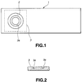
- Fig.1 shows an example of a lid plate provided with such cleavage valve.
- a circular opening 2 is provided in the lid plate 1 shaped to conform to the opening shape of the cell can, and a metal foil 3 is welded, such as by laser welding, to close the opening 2.
- the shape of the opening 2, which is circular in the present embodiment, may be of any suitable shape, such as elliptical shape.
- the circular shape is preferred in view of operational stability and ease in manufacture.
- the metal foil 3, which is square-shaped in the present embodiment, may be of any desired shape, provided that it can stop the opening 2.
- the metal foil 3 may, for example, be circular for matching to the shape of the opening 2.
- the metal foil 3 is formed with a circular thin-walled portion 3a, in its area facing the inside of the opening 2, and is adapted to be cleft beginning from this portion on the occasion of rise in the internal pressure.
- the thin-walled portion 3a may be formed by any optional technique, such as by etching, electro-forming or stamping.
- the electro-forming method is preferred in view of fluctuations in the cleavage pressure.
- the electroforming which is so-called electro-casting, is such a technique in which a pattern is formed by a photoresist, an insulating film is prepared, a substrate is supplied with current, and preset metal is allowed to undergo crystal growth to form an electrically conductive portion to produce a pattern of lands and valleys under a principle similar to that used for plating.
- This electro-forming is an optimum technique for controlling the cleavage pressure to a narrow tolerance since the crystal growth can be controlled electrically in contradistinction to the similar photoetching method and hence a film can be prepared with a high processing accuracy.
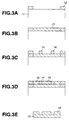
- a first resist pattern 12 which determines the outer shape of the cleavage valve is formed on the substrate 11 by a photolithographic process employing a photoresist. Using this resist pattern as a mask, Ni is plated on the substrate.
- a circular second resist pattern 14 is formed to the shape of a cleavage and again Ni is plated thereon as shown in Fig.3D to form a second Ni plating film 15.
- the combined film thickness of the second Ni plating film 15 and the previously formed first Ni plating film 13 may, for example, be 40 ⁇ m or more.
- the first Ni plating film 13 and the second Ni plating film 15 are formed and the resist patterns 12, 14 are fused and removed to produce a cleavage valve having the thin-walled portion formed therein to he shape of the second resist pattern 14, as shown in Fig.3E.
- a circular groove 22 is formed by pressing in a circular metal plate 21 to form a thin-walled portion.
- punching is done consecutively, traces of connecting portions to a hoop material are left as four projections 23.
- an outer peripheral surface 22a of the groove 22 runs somewhat obliquely, for example, at an inclination of the order of 20°, as shown in Fig.5.
- an inner peripheral surface 22b extends substantially vertically. This eliminates the risk of creasing in a cleavage valve (a circular area inwardly of the groove 22).
- Fig.6 shows the technique of continuously forming the cleavage valve.
- a hoop material 24 having positioning holes 25 is punched at a preset interval to determine the outer shape of the metal plate 21, and grooves 22 then are formed by stamping.
- the metal plate 21 is then handled in this state and ultimately a connecting plate 26 is severed. This enables continuous supply of cleavage valves in a manner convenient for line automation.
- a clad material obtained on bonding a thick metal foil and a thin metal foil together, may be used.
- Figs.7 and 8 show a cleavage valve employing a clad material.
- the metal foil 3 is made up of a thick metal foil 31 and a thin metal foil 32.
- the thick metal foil 31 is removed in an area facing the inside of the opening 2 to a diameter smaller than the opening 2 to delimit a circular thin-walled portion 3b.
- the metal foil 3 is preferably of a thickness of 40 to 100 ⁇ m. If the thickness is less than 40 ⁇ m, sufficient strength can hardly be developed on, for example, laser welding. Conversely, the thickness exceeding 100 ⁇ m is not desirable in view of productivity and also because of non-smooth cleavage.
- the metal foil 3 is preferably coated a fluorine-based water-proofing agent after bonding the metal foil 3 to the opening 2. If the metal foil 3 is formed by the electro-forming method to form the groove-shaped thin-walled portion 3a, and water droplets are deposited thereon, rusting tends to be produced because of difficulties in evaporation of water. If a fluorine-based water-proofing agent is coated, it is possible to prevent rusting to improve operational reliability.
- an area of the opening 2 needs to be set to an optimum value depending on the inner cell volume.
- the inner cell volume (in cm 3 ) divided by the area of the above opening (in cm 2 ) is set so that 40 ⁇ K ⁇ 350 to optimize the cleavage pressure at all times.
- the area of the opening 2 as large as possible is preferred, its upper limit is approximately one-half the area of the lid plate in view of the shape of the lid plate 1. If the physical limitation of the lid plate 1 is taken into account, the lower limit of the above K value is 40. If the opening 2 is of a true circular shape, the K value has a lower limit value of approximately 50. Conversely, if the K value is too large, that is if the area of the opening 2 is too small, the cleavage pressure will be excessive, thus producing cleavage of the weld and dilation of the cell can.
- the K value is preferably in a range from 80 to 320 and more preferably in a range from 85 to 240.
- an electrode terminal for example, is provided on a lid plate of the cell can.
- Figs.9 and 10 show an example of a lid plate 41 of a cell can having some width. At a mid portion of the lid plate 41 is caulked a terminal pin 42 via a gasket 43. This terminal pin 42 is electrically connected via a lead to, for example, a positive terminal, in a manner not shown.
- a cleavage valve 44 On both sides of the terminal pin 42 are arranged a cleavage valve 44 and a solution injection port 45 for injecting the electrolytic solution.
- the cleavage valve 44 since the lid plate 41 is of some width, the cleavage valve 44 has a substantially circular shape.
- Figs. 11 and 12 show an example of the lid plate 41. Since the lid plate 41 of the present example is of narrow width, the cleavage valve 44 is of an oblong shape. The rim portion of the solution injection port 45 is formed with a step to improve mechanical strength. The provision of the step is aimed at assuring sufficient resistance against the force applied at the time of welding the solution injection port 45 using a micro-sized globule.
- the non-aqueous electrolyte secondary cell according to the present invention has the above-described cleavage valve as its main feature. Otherwise, the cell may be constructed similarly to the conventional non-aqueous electrolyte secondary cell.
- an active material for the negative electrode of the non-aqueous electrolyte secondary cell a variety of materials may be used depending on the type of the cell desired to be fabricated.
- the active material for the negative electrode there is a carbonaceous material capable of doping and undoping metal ions, above all, lithium ions, that contribute to the cell reaction.
- this carbonaceous material such carbonaceous material of low crystallinity produced on firing at a lower temperature not higher than 2000°C or a carbonaceous material of low crystallinity obtained on processing a crystallizable starting material at an elevated temperature in the vicinity of 3000°C, may be used.
- carbonaceous materials petroleum pitch, a binder pitch, a high-molecular resin or green coke, are most preferred.
- a low crystallinity carbonaceous material having a plane-to-plane spacing of the (002) planes not less than 3.70 A ° and a true density less than 1.70 g/cc and having no heat emission peak at a temperature not lower than 700°C on differential thermal analysis in an air stream or a high crystallinity carbonaceous material having a high negative electrode mixture charging ratio and a true specific gravity not lower than 2.10 g/cc, may be used.
- the negative electrode may be formed of metal lithium, a lithium alloy or a polymer doped with lithium.
- metal oxides, metal sulfides or specified polymers may be used depending on the type of the cell desired to be produced.
- a lithium ion secondary cell is to be fabricated, a lithium complex oxide containing Li x MO 2 , where M is at least one transition metal, preferably one of Co, Ni or Fe, with 0.05 ⁇ X ⁇ 1.10.
- the lithium complex oxide may be exemplified by LiCoO 2 , LiNiO 2 and LiNi y Co (1-y) O 2 , with 0.05 ⁇ X ⁇ 1.10 and 0 ⁇ y ⁇ 1.
- LiMnO 4 may also be used.
- the above-mentioned lithium complex oxide may be obtained on mixing carbonates of, for example, lithium, cobalt or nickel, depending on the compositions, and firing the resulting mixture in an oxygen-containing atmosphere at a temperature from 400° to 1000°C.
- the starting material is not limited to carbonates and the lithium complex oxide may be fabricated from hydroxides or oxides.
- metal lithium or lithium alloys are used as the negative electrode, it is possible to use compounds that cannot undope lithium on initial charging, for example, a variety of oxides, such as manganese dioxide or titanium oxide, sulfides, such as titanium oxide or polymers, such as polyaniline, may be used as positive electrodes.
- oxides such as manganese dioxide or titanium oxide
- sulfides such as titanium oxide
- polymers such as polyaniline
- non-aqueous electrolyte used in the non-aqueous electrolyte secondary cell it is possible to use a well-known non-aqueous electrolytic solution obtained on dissolving an electrolyte in an organic solvent.
- esters such as propylene carbonate, ethylene carbonate or ⁇ -butyrolactone, diethyl ether, tetrahydrofuran, substituted tetrahydroturan, dioxolane, pyran or derivatives thereof, ethers, such as dimethoxyethane or diethoxyethane, 3-substituted-2-oxazolidinines, such as 3-methyl-2-oxazolidinone, sulforane, methyl sulforane, acetonitrile or propionitrile, may be used. These may be used alone or in combination.
- Examples of the electrolytes that may be used include lithium perchlorates, lithium boron fluorides, lithium phosphor fluorides, lithium chloride aliminates, lithium halogenides and trifluoromethane lithium sulfonates.
- the non-aqueous electrolyte may also be a solid, in which case conventional well-known solid electrolytes may be used.
- the electrode structure may be comprised of winding of a strip-shaped electrode fabricated on coating an active material on a current collector.
- the electrode may be comprised of layered plate-shaped electrodes on which an active material is held by coating or firing an active material on a current collector.
- the cell may be of an angular, cylindrical or any other suitable configuration.
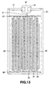
- Fig. 13 shows a typical cell comprised of a positive electrode 51, a negative electrode 52 and a separator 53 layered together and wound in a coil which is then housed in a cell can 54.
- the cell element (wound pair) has its outermost rim secured by a winding end tape 55 and secured in the cell can 54 by a spring plate 56.
- the cell element has its upper and lower ends sandwiched between insulating layers 57, 58 so as to be stably housed in the cell can 54.
- the above-mentioned lid plate 41 is secured to the cell can 54 to seal the opening.
- a positive electrode lead 57 derived from the positive electrode 51.
- the positive electrode lead 57 is usually designed to a longer length and its extracted end is folded and connected to the terminal pin 42.
- the extracted portion of the positive electrode lead 57 may be folded on itself on the side of the cleavage valve 44 as shown in Fig. 14 or on the opposite side, that is on the side of the solution injection port 45, as shown in Fig. 15.
- the present inventors have found that the later method is preferred. In the usual use state, it does not matter on which side the extracted portion of the positive electrode lead 57 is folded on itself. It has however been found that if, in a descent test, the extracted portion of the positive electrode lead 57 is folded on itself on the side of the cleavage valve 44, there is the possibility of in advertent actuation of the cleavage valve 44.
- a negative electrode was first prepared in the following manner.
- the slurry of the negative electrode mixture was coated on both surfaces of a strip-shaped copper foil 10 ⁇ m thick and dried.
- the resulting dried mass was compression molded in a roll press to produce a band-shaped negative electrode 1.
- This band-shaped negative electrode was designed so that the thickness of the mixture was 80 ⁇ m thick on both sides, with its width and length being 41.5 mm and 505 mm, respectively.
- a positive electrode was produced in the following manner.
- LiCoO 2 An active material for the positive electrode (LiCoO 2 ) was synthesized as follows: Lithium carbonate and cobalt carbonate were mixed together so that its Li/Co molar ratio is equal to 1 and the resulting mixture was fired in air at 900°C for five hours. The results of X-ray diffractiometry testified to good coincidence with LiCoO 2 of the JCPDS card. The fired product was pulverized in a mortar to LiCoO 2 .
- the band-shaped positive and negative electrodes and a separator formed by a micro-porous polypropylene film were layered together and wound a number of times on a diamond-shaped take-up core.
- the trailing end of the layered mass was secured using an adhesive tape 40 mm wide and deformed under pressure to fabricate an oblong-shaped wound electrode member.
- This oblong-shaped wound electrode member was housed in a nickel-plated square-shaped cell can of iron along with a spring plate and an insulating plate was arranged on each of the upper and lower surfaces of the electrode member.
- an end of the nickel lead of the negative electrode was press-attached to the electrode, whilst the end of the nickel lead was welded to the positive electrode.
- an end of the aluminum lead of the positive electrode was attached to the positive electrode, with the other end of the lead being welded by laser to a cell lid. In the present Example, no cleavage valve was fitted on the cell lid.
- An electrolytic solution obtained on dissolving 1 mol of LiPF 6 in a mixed solvent composed of 50 vol% of propylene carbonate and 50 vol% of diethyl carbonate, was injected via the electrolytic solution injection port. This port was then sealed by electrically welding a steel globule.
- Sample cells were prepared in the same way as in comparative sample 1 except using a cell lid provided with a cleavage valve.
- the cleavage valve was fabricated by providing an opening in the cell lid, punching a metal foil, formed with a circular pattern (thin-walled portion) by the electro-forming method, to a predetermined size, and by laser-welding the punched metal foil in the opening in the cell lid.
- the entire thickness of the metal foil was 50 ⁇ m and the circular pattern was varied in a range from 5 to 15 ⁇ m so that the valve would be cleft at a preset pressure.
- the gas could be relieved in a state of only little deformation in the cell can.
- the gas could be relieved in a state of only little deformation in the cell.
- a resistance-to-environment test was conducted using a cell of sample 3.
- coating of the metal foil constituting the cleavage valve is indispensable for improving reliability in practical application.
- the metal foil constituting the cleavage valve is prepared by an electro-forming method, a cladding method, a stamping method, an etching method and a method directly using the foil. For each of these foils, variations in the cleavage pressure was checked using air. The results are shown in Table 5.
Landscapes
- Chemical & Material Sciences (AREA)
- Chemical Kinetics & Catalysis (AREA)
- Electrochemistry (AREA)
- General Chemical & Material Sciences (AREA)
- Engineering & Computer Science (AREA)
- Manufacturing & Machinery (AREA)
- Materials Engineering (AREA)
- Gas Exhaust Devices For Batteries (AREA)
- Secondary Cells (AREA)
- Sealing Battery Cases Or Jackets (AREA)
Abstract
Description
- This invention relates to a non-aqueous electrolyte secondary cell. More particularly, it relates to a non-aqueous electrolyte secondary cell having a cleavage valve which, in case of an increased internal pressure, releases the pressure by exploiting this increased internal pressure.
- Recently, with coming into widespread use of portable equipments, such as video cameras or cassette recorders, there is raised an increasing demand for secondary cells that can be repeatedly used in place of the disposable primary cells.
- The majority of currently used secondary cells are nickel-cadmium cells employing an alkali electrolyte liquid. However, this aqueous solution type cell has a discharging potential as low as approximately 1.2 V and a large cell weight and volume such that it cannot satisfactorily meet the demand for a cell having a high energy density. The aqueous solution type cell also has a drawback that it has a self discharge rate as high as approximately 20% per month at ambient temperature.
- Thus, a non-aqueous electrolyte secondary cell employing a non-aqueous solvent as the electrolyte solution and also employing light metals, such as lithium as the negative electrode, is under investigations. This non-aqueous electrolyte secondary cell has a voltage as high as 3 V or higher, a high energy density and a low self-discharge rate.
- However, this sort of the secondary cell also can hardly be put to practical use because of a drawback that metal lithium used for the negative electrode undergoes dendritic crystal growth to contact with the positive electrode, due to repetition of charging/discharging, as a result of which shorting tends to be produced in the cell to lower the service life of the cell.
- In order to overcome this drawback, a non-aqueous electrolyte secondary cell employing, as a negative electrode, an alloy obtained on alloying lithium with other metals, is also under investigations.
- In this case, however, the alloy is turned into comminuted particles, due to repetition of charging/discharging, thus again lowering the service life of the cell.
- Under this situation, there is proposed a non-aqueous electrolyte secondary cell employing a carbonaceous material, such as coke, as an active material for the negative electrode.
- This secondary cell is free of the above-mentioned drawbacks in the negative electrode and hence is superior in cyclic service life characteristics. If a lithium transition metal complex oxide is used as an active material for the positive electrode, the service life of the cell is prolonged to enable realization of the non-aqueous electrolyte secondary cell having the desired high energy density.
- Meanwhile, in a non-aqueous electrolyte secondary cell employing the carbonaceous material as a negative electrode, there is required a pressure relieving mechanism for promptly releasing the pressure when the cell is subjected to an abnormal temperature rise or combustion.
- If this pressure relieving mechanism comes into operation to release the gas when the internal pressure in the cell reaches a predetermined pressure, there can be provided an extremely safe cell free from explosions or the like.
- It is therefore an object of the present invention to provide an extremely safe non-aqueous electrolyte secondary cell capable of promptly releasing an increasing internal pressure and which is free from explosion or the like.
- As a result of repeated investigations towards achieving the above object, the present inventors have arrived at the information that a non-aqueous electrolyte secondary cell free from explosions or the like can be provided by providing a cleavage valve that is cleft in case of rise in the internal pressure of the cell and by optimizing the diameter of the opening of the valve in association with the internal capacity of the cell to optimize the operating pressure to carry out satisfactory gas release at the time of abnormal pressure increase or on combustion.
- The present invention, completed on the basis of this information, resides in a non-aqueous electrolyte secondary cell having a cleavage valve which is realized by bonding a metal foil to an opening in the valve. The metal foil is cleft due to rise in the internal pressure in the cell to release the pressure. A value K corresponding to the internal cell volume in cm3 divided by the area of the opening in cm2 is such that 40 ≤ K ≤ 100 µm.
- By selecting the K value to be a suitable value, the cleavage valve is in operation promptly when the internal pressure reaches a predetermined pressure in order to release the pressure. Thus, there is no risk of dilation or explosion of the cell to assure high operational safety.
- Thus, the present invention provides an extremely safe cell free from explosions since gas release may be promptly realized on the occasion of rise in the internal pressure in the cell.
-
- Fig.1 is a schematic plan view showing an illustrative structure of a cleavage valve.
- Fig.2 is a schematic cross-sectional view showing essential portions of a metal foil formed by an electroforming method.
- Fig.3 is a schematic cross-sectional view showing the method for forming the cleavage valve by the electro-forming method, step-by-step.
- Fig.4 is a schematic cross-sectional view showing a typical cleavage valve produced by a stamping method.
- Fig.5 is a schematic cross-sectional view showing essential portions of a groove formed by pressing.
- Fig.6 is a schematic plan view showing essential portions of a supply device continuously supplying cleavage valves produced by the stamping method.
- Fig.7 is a schematic plan view showing another illustrative structure of the cleavage valve.
- Fig.8 is a schematic cross-sectional view showing a typical metal foil formed of a clad material.
- Fig.9 is a schematic plan view showing a typical lid plate.
- Fig.10 is a schematic cross-sectional view showing the lid plate of Fig.9.
- Fig.11 is a schematic plan view showing another typical lid plate.
- Fig.12 is a schematic cross-sectional view showing the lid plate of Fig. 11.
- Fig.13 is a schematic cross-sectional view showing a typical cell structure.
- Fig.14 is a schematic cross-sectional view showing the state in which a positive terminal lead is folded in a direction towards the cleavage valve side.
- Fig.15 is a schematic cross-sectional view showing the state in which a positive terminal lead is folded in a direction opposite to the cleavage valve side.
-
- A non-aqueous electrolyte secondary cell of the present invention includes a cleavage valve obtained on bonding a metal foil to an opening provided in a cell can or a lid plate used for hermetically sealing the can. The cleavage valve is cleft on the occasion of rise in the internal pressure to cleave the metal foil to relieve the pressure.
- Fig.1 shows an example of a lid plate provided with such cleavage valve. A
circular opening 2 is provided in thelid plate 1 shaped to conform to the opening shape of the cell can, and ametal foil 3 is welded, such as by laser welding, to close theopening 2. - The shape of the
opening 2, which is circular in the present embodiment, may be of any suitable shape, such as elliptical shape. The circular shape, however, is preferred in view of operational stability and ease in manufacture. - The
metal foil 3, which is square-shaped in the present embodiment, may be of any desired shape, provided that it can stop theopening 2. Themetal foil 3 may, for example, be circular for matching to the shape of theopening 2. - The
metal foil 3 is formed with a circular thin-walled portion 3a, in its area facing the inside of theopening 2, and is adapted to be cleft beginning from this portion on the occasion of rise in the internal pressure. - For this
metal foil 3, the thin-walled portion 3a may be formed by any optional technique, such as by etching, electro-forming or stamping. The electro-forming method is preferred in view of fluctuations in the cleavage pressure. - The electroforming, which is so-called electro-casting, is such a technique in which a pattern is formed by a photoresist, an insulating film is prepared, a substrate is supplied with current, and preset metal is allowed to undergo crystal growth to form an electrically conductive portion to produce a pattern of lands and valleys under a principle similar to that used for plating.
- This electro-forming is an optimum technique for controlling the cleavage pressure to a narrow tolerance since the crystal growth can be controlled electrically in contradistinction to the similar photoetching method and hence a film can be prepared with a high processing accuracy.
- The technique for fabricating the cleavage valve by the above electro-forming is shown in Fig.3. For fabricating the cleavage valve, a
first resist pattern 12 which determines the outer shape of the cleavage valve is formed on thesubstrate 11 by a photolithographic process employing a photoresist. Using this resist pattern as a mask, Ni is plated on the substrate. - This forms a first Ni plating
film 13, as shown in Fig.3B. It is the thickness of this first Ni platingfilm 13 that determines the thickness of the thin-walled portion 3a. Therefore, the first Niplating film 13 is set to a thickness of the order of 10 to 12 µm in order to permit smooth cleavage of the cleavage valve at the pressure rise time. - Then, as shown in Fig.3C, a circular
second resist pattern 14 is formed to the shape of a cleavage and again Ni is plated thereon as shown in Fig.3D to form a secondNi plating film 15. The combined film thickness of the second Ni platingfilm 15 and the previously formed first Ni platingfilm 13 may, for example, be 40 µm or more. - The first
Ni plating film 13 and the secondNi plating film 15 are formed and the resistpatterns pattern 14, as shown in Fig.3E. - With a cleavage valve by stamping, a
circular groove 22 is formed by pressing in acircular metal plate 21 to form a thin-walled portion. In the present instance, since punching is done consecutively, traces of connecting portions to a hoop material are left as fourprojections 23. - If the
groove 22 is formed by this stamping, it is preferred that an outerperipheral surface 22a of thegroove 22 runs somewhat obliquely, for example, at an inclination of the order of 20°, as shown in Fig.5. On the other hand, an innerperipheral surface 22b extends substantially vertically. This eliminates the risk of creasing in a cleavage valve (a circular area inwardly of the groove 22). - Fig.6 shows the technique of continuously forming the cleavage valve. A
hoop material 24 having positioning holes 25 is punched at a preset interval to determine the outer shape of themetal plate 21, andgrooves 22 then are formed by stamping. Themetal plate 21 is then handled in this state and ultimately a connectingplate 26 is severed. This enables continuous supply of cleavage valves in a manner convenient for line automation. - Alternatively, a clad material, obtained on bonding a thick metal foil and a thin metal foil together, may be used. Figs.7 and 8 show a cleavage valve employing a clad material. The
metal foil 3 is made up of athick metal foil 31 and athin metal foil 32. Thethick metal foil 31 is removed in an area facing the inside of theopening 2 to a diameter smaller than theopening 2 to delimit a circular thin-walled portion 3b. - In any case, the
metal foil 3 is preferably of a thickness of 40 to 100 µm. If the thickness is less than 40 µm, sufficient strength can hardly be developed on, for example, laser welding. Conversely, the thickness exceeding 100 µm is not desirable in view of productivity and also because of non-smooth cleavage. - On the
metal foil 3 is preferably coated a fluorine-based water-proofing agent after bonding themetal foil 3 to theopening 2. If themetal foil 3 is formed by the electro-forming method to form the groove-shaped thin-walled portion 3a, and water droplets are deposited thereon, rusting tends to be produced because of difficulties in evaporation of water. If a fluorine-based water-proofing agent is coated, it is possible to prevent rusting to improve operational reliability. - In the above-described cleavage valve, as described above, an area of the
opening 2 needs to be set to an optimum value depending on the inner cell volume. - In the present invention, the inner cell volume (in cm3) divided by the area of the above opening (in cm2) is set so that 40 ≤ K ≤ 350 to optimize the cleavage pressure at all times.
- Although the area of the
opening 2 as large as possible is preferred, its upper limit is approximately one-half the area of the lid plate in view of the shape of thelid plate 1. If the physical limitation of thelid plate 1 is taken into account, the lower limit of the above K value is 40. If theopening 2 is of a true circular shape, the K value has a lower limit value of approximately 50. Conversely, if the K value is too large, that is if the area of theopening 2 is too small, the cleavage pressure will be excessive, thus producing cleavage of the weld and dilation of the cell can. - Thus, for practical application, the K value is preferably in a range from 80 to 320 and more preferably in a range from 85 to 240.
- In addition to the cleavage valve, an electrode terminal, for example, is provided on a lid plate of the cell can.
- Figs.9 and 10 show an example of a
lid plate 41 of a cell can having some width. At a mid portion of thelid plate 41 is caulked aterminal pin 42 via agasket 43. Thisterminal pin 42 is electrically connected via a lead to, for example, a positive terminal, in a manner not shown. - On both sides of the
terminal pin 42 are arranged acleavage valve 44 and asolution injection port 45 for injecting the electrolytic solution. In the present embodiment, since thelid plate 41 is of some width, thecleavage valve 44 has a substantially circular shape. - Figs. 11 and 12 show an example of the
lid plate 41. Since thelid plate 41 of the present example is of narrow width, thecleavage valve 44 is of an oblong shape. The rim portion of thesolution injection port 45 is formed with a step to improve mechanical strength. The provision of the step is aimed at assuring sufficient resistance against the force applied at the time of welding thesolution injection port 45 using a micro-sized globule. - The non-aqueous electrolyte secondary cell according to the present invention has the above-described cleavage valve as its main feature. Otherwise, the cell may be constructed similarly to the conventional non-aqueous electrolyte secondary cell.
- As an active material for the negative electrode of the non-aqueous electrolyte secondary cell, a variety of materials may be used depending on the type of the cell desired to be fabricated. Among the active material for the negative electrode, there is a carbonaceous material capable of doping and undoping metal ions, above all, lithium ions, that contribute to the cell reaction.
- As this carbonaceous material, such carbonaceous material of low crystallinity produced on firing at a lower temperature not higher than 2000°C or a carbonaceous material of low crystallinity obtained on processing a crystallizable starting material at an elevated temperature in the vicinity of 3000°C, may be used. Among the carbonaceous materials, petroleum pitch, a binder pitch, a high-molecular resin or green coke, are most preferred. In addition, completely carbonized pyrocarbon, cokes (pitch coke or petroleum coke), artificial graphites, natural graphites, carbon black (acetylene black or the like), vitreous carbon, fired organic high-molecular materials (natural high-molecular materials fired in an inert gas stream or in vacuum at a suitable temperature hot lower than 500°C) or a mixture of carbon fibers with resin-containing pitches or resins showing high sinterability, such as furan resins, divinyl benzene, polyvinylidene fluoride or polyvinylidene chloride, may be used. In particular, a low crystallinity carbonaceous material having a plane-to-plane spacing of the (002) planes not less than 3.70 A ° and a true density less than 1.70 g/cc and having no heat emission peak at a temperature not lower than 700°C on differential thermal analysis in an air stream, or a high crystallinity carbonaceous material having a high negative electrode mixture charging ratio and a true specific gravity not lower than 2.10 g/cc, may be used.
- The negative electrode may be formed of metal lithium, a lithium alloy or a polymer doped with lithium.
- As an active material for the positive electrode of the non-aqueous electrolyte secondary cell, metal oxides, metal sulfides or specified polymers may be used depending on the type of the cell desired to be produced. If a lithium ion secondary cell is to be fabricated, a lithium complex oxide containing LixMO2, where M is at least one transition metal, preferably one of Co, Ni or Fe, with 0.05 ≤ X ≤ 1.10. The lithium complex oxide may be exemplified by LiCoO2, LiNiO2 and LiNiyCo(1-y)O2, with 0.05 ≤ X ≤ 1.10 and 0<y<1. LiMnO4 may also be used.
- The above-mentioned lithium complex oxide may be obtained on mixing carbonates of, for example, lithium, cobalt or nickel, depending on the compositions, and firing the resulting mixture in an oxygen-containing atmosphere at a temperature from 400° to 1000°C. The starting material is not limited to carbonates and the lithium complex oxide may be fabricated from hydroxides or oxides.
- If metal lithium or lithium alloys are used as the negative electrode, it is possible to use compounds that cannot undope lithium on initial charging, for example, a variety of oxides, such as manganese dioxide or titanium oxide, sulfides, such as titanium oxide or polymers, such as polyaniline, may be used as positive electrodes.
- As a non-aqueous electrolyte used in the non-aqueous electrolyte secondary cell, it is possible to use a well-known non-aqueous electrolytic solution obtained on dissolving an electrolyte in an organic solvent.
- As the organic solvents, esters, such as propylene carbonate, ethylene carbonate or γ-butyrolactone, diethyl ether, tetrahydrofuran, substituted tetrahydroturan, dioxolane, pyran or derivatives thereof, ethers, such as dimethoxyethane or diethoxyethane, 3-substituted-2-oxazolidinines, such as 3-methyl-2-oxazolidinone, sulforane, methyl sulforane, acetonitrile or propionitrile, may be used. These may be used alone or in combination.
- Examples of the electrolytes that may be used include lithium perchlorates, lithium boron fluorides, lithium phosphor fluorides, lithium chloride aliminates, lithium halogenides and trifluoromethane lithium sulfonates.
- The non-aqueous electrolyte may also be a solid, in which case conventional well-known solid electrolytes may be used.
- The electrode structure may be comprised of winding of a strip-shaped electrode fabricated on coating an active material on a current collector. Alternatively, the electrode may be comprised of layered plate-shaped electrodes on which an active material is held by coating or firing an active material on a current collector.
- The cell may be of an angular, cylindrical or any other suitable configuration.
- Fig. 13 shows a typical cell comprised of a
positive electrode 51, anegative electrode 52 and aseparator 53 layered together and wound in a coil which is then housed in a cell can 54. The cell element (wound pair) has its outermost rim secured by a windingend tape 55 and secured in the cell can 54 by aspring plate 56. Moreover, the cell element has its upper and lower ends sandwiched between insulatinglayers - The above-mentioned
lid plate 41 is secured to the cell can 54 to seal the opening. To theterminal pin 42 is connected apositive electrode lead 57 derived from thepositive electrode 51. Thus, with the present cell, the cell can 54 and theterminal pin 52 operate as negative and positive electrodes, respectively. - For avoiding inadvertent breakage and for assuring a facilitated connecting operation, the
positive electrode lead 57 is usually designed to a longer length and its extracted end is folded and connected to theterminal pin 42. - The extracted portion of the
positive electrode lead 57 may be folded on itself on the side of thecleavage valve 44 as shown in Fig. 14 or on the opposite side, that is on the side of thesolution injection port 45, as shown in Fig. 15. The present inventors have found that the later method is preferred. In the usual use state, it does not matter on which side the extracted portion of thepositive electrode lead 57 is folded on itself. It has however been found that if, in a descent test, the extracted portion of thepositive electrode lead 57 is folded on itself on the side of thecleavage valve 44, there is the possibility of in advertent actuation of thecleavage valve 44. - Specified examples of the present invention will be explained further with reference being had to experimental results.
- A negative electrode was first prepared in the following manner.
- As a starting material of an active material for a negative electrode, 10 to 20 wt% of functional groups containing oxygen are introduced into it for oxygen cross-linking. The resulting mass was fired in an inert gas stream at a temperature of 1000°C to produce a carbonaceous material having properties close to those of vitreous carbon. The results of X-ray diffractiometry revealed that the plane-to lane separation between (002) planes amounted to 3.76 A °. Similarly, measurements by a pycnometer revealed that the true specific gravity was 1.58 g/cm3. This carbonaceous material was crushed to powders of the carbonaceous material having an average particle size of 10 µm.
- 90 parts by weight of the powders of the carbonaceous material thus produced were mixed with 10 parts by weight of polyvinylidene fluoride (PVDF) as a binder to prepare a negative electrode mixture. This negative electrode mixture was then dispersed in N-methyl pyrrolidone to a paste-like slurry of a negative electrode mixture.
- The slurry of the negative electrode mixture was coated on both surfaces of a strip-shaped copper foil 10 µm thick and dried. The resulting dried mass was compression molded in a roll press to produce a band-shaped
negative electrode 1. This band-shaped negative electrode was designed so that the thickness of the mixture was 80 µm thick on both sides, with its width and length being 41.5 mm and 505 mm, respectively. - A positive electrode was produced in the following manner.
- An active material for the positive electrode (LiCoO2) was synthesized as follows: Lithium carbonate and cobalt carbonate were mixed together so that its Li/Co molar ratio is equal to 1 and the resulting mixture was fired in air at 900°C for five hours. The results of X-ray diffractiometry testified to good coincidence with LiCoO2 of the JCPDS card. The fired product was pulverized in a mortar to LiCoO2. 91 wt% of this LiCoO2, thus obtained, 6 wt% of graphite as an electrically conductive material and 3 wt% of polyvinylidene fluoride as a binder were mixed to prepare a positive electrode mixture which then was dispersed in N-methyl-2-pyrrolidone to give a slurry of the positive electrode mixture. This slurry of the positive electrode mixture was coated on both surfaces of a band-shaped aluminum foil, 20 µm in thickness, as a positive electrode current collector, and dried. The resulting product was then molded under compression by a roll press to fabricate a positive electrode. Meanwhile, the thickness of the mixture of the band-shaped aluminum foil was set to 80 µm on each surface, with its width and length being set to 39.5 mm and 490 mm, respectively.
- The band-shaped positive and negative electrodes and a separator formed by a micro-porous polypropylene film were layered together and wound a number of times on a diamond-shaped take-up core. The trailing end of the layered mass was secured using an adhesive tape 40 mm wide and deformed under pressure to fabricate an oblong-shaped wound electrode member.
- This oblong-shaped wound electrode member was housed in a nickel-plated square-shaped cell can of iron along with a spring plate and an insulating plate was arranged on each of the upper and lower surfaces of the electrode member. For collecting the current of the negative electrode, an end of the nickel lead of the negative electrode was press-attached to the electrode, whilst the end of the nickel lead was welded to the positive electrode. Also, for collecting the current of the positive electrode, an end of the aluminum lead of the positive electrode was attached to the positive electrode, with the other end of the lead being welded by laser to a cell lid. In the present Example, no cleavage valve was fitted on the cell lid.
- An electrolytic solution, obtained on dissolving 1 mol of LiPF6 in a mixed solvent composed of 50 vol% of propylene carbonate and 50 vol% of diethyl carbonate, was injected via the electrolytic solution injection port. This port was then sealed by electrically welding a steel globule.
- By the above process, a square-shaped secondary cell, having a thickness, a height and a width of 9 mm, 48 mm and 34 mm, was prepared.
- Sample cells were prepared in the same way as in
comparative sample 1 except using a cell lid provided with a cleavage valve. - The cleavage valve was fabricated by providing an opening in the cell lid, punching a metal foil, formed with a circular pattern (thin-walled portion) by the electro-forming method, to a predetermined size, and by laser-welding the punched metal foil in the opening in the cell lid.
- It was found impossible to prepare the
opening 2 mm or less in diameter. - The entire thickness of the metal foil was 50 µm and the circular pattern was varied in a range from 5 to 15 µm so that the valve would be cleft at a preset pressure.
- The conditions of the cleavage valve was varied as shown in Table 1 to prepare
samples 1 to 4. - These cells were charged to 4.2 V and a combustion test was conducted using a gas burner. The results are shown in Table 1.

- If the diameter of the opening was not less than 2.8 mm, the gas could be relieved in a state of only little deformation in the cell can.
- A set of square-shaped secondary cells with the thickness, width and height of 14 mm, 34 mm and 48 mm, respectively, were prepared with the conditions of the cleavage valves changed, with the other conditions remaining unchanged from those of
samples 1 to 4. - These cells were charged to 4.2 V and subjected to a combustion test using a gas burner. The results are shown in Table 2.

- If the diameter of the opening is not less than 2.8 mm, the gas could be relieved in a state of only little deformation in the cell.
- A set of square-shaped secondary cells with the thickness, width and height of 6mm, 30mm and 48 mm, respectively, were prepared under conditions of the cleavage vales changed, with the other conditions remaining unchanged from those of
samples 1 to 4. - These cells were charged to 4.2 V and subjected to a combustion test using a gas burner. The results are shown in Table 3
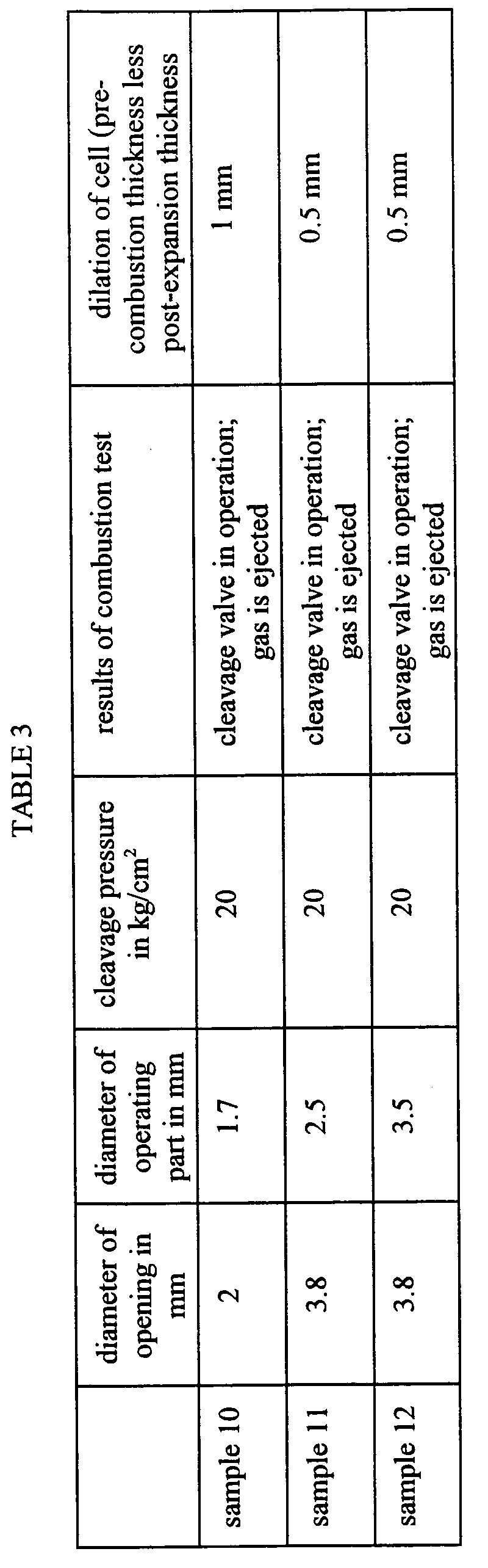
- It was found that, if the diameter of the opening was 2 mm or more, the gas could be released with only little deformation of the cell can.
- The results of the
above samples 1 to 12, put into order in terms of the K-value (cell volume/cleavage area), are shown in table 4.
- As may seen from Table 4, it is effective to have optimum values for K.
- A resistance-to-environment test was conducted using a cell of
sample 3. - In the fully charged state of 4.2 V, a 90% humidification test was conducted under 60° and 90% RH to check the appearance of the cleavage valve. Tests conducted on 20 cells indicated that minute rust was generated in cleft portion of ten cells.
- Thus, after welding the metal foil on the opening, a fluorine-based water-proofing agent (trade name: NOX guard) was dripped and dried. Similar tests conducted on the dried products indicated that no rusting occurred.
- Therefore, it may be said that coating of the metal foil constituting the cleavage valve is indispensable for improving reliability in practical application.
- The metal foil constituting the cleavage valve is prepared by an electro-forming method, a cladding method, a stamping method, an etching method and a method directly using the foil. For each of these foils, variations in the cleavage pressure was checked using air. The results are shown in Table 5.

- The electro-forming and mark stamping methods gave good results because of only little fluctuations. Second to these methods was the cladding method employing a thick foil and a thin foil in combination. For practical application, these three sorts are thought to be preferred. If the etching method is used, difficulties are estimated to be met in management because of significant fluctuations.
- A sample having an electrode structure similar to that of
sample 3 and having the folding direction of the positive terminal lead towards the cleavage valve (below the cleavage valve) and another sample having the folding direction of the positive terminal lead in the opposite direction, that is in a direction away from the cleavage valve. - These indicated no significant difference in the above test.
- However, the two samples showed difference in the descent test. The results of the descent test, in which the cells were dropped from a height of 1.5 m, are shown in Table 6.
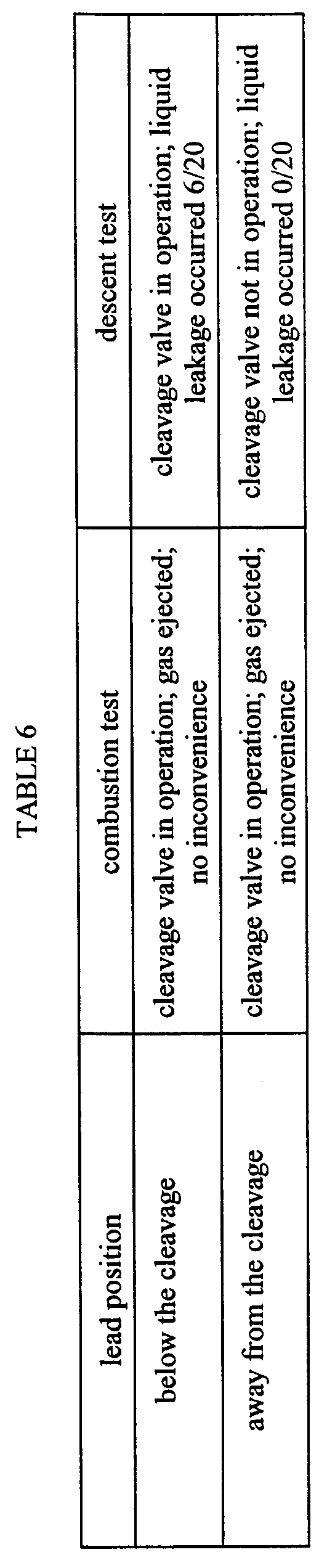
- The results indicated significant difference depending on the lead position, that is that it is more preferred to bend the lead in the direction away from the cleavage area. By fabricating the valve in this manner, it becomes possible to produce a cell having high safety.
Claims (12)
- A non-aqueous electrolyte secondary cell having a cleavage valve which is realized by bonding a metal foil to an opening in the cell, said metal foil being cleft due to rise in the internal pressure in the cell to release the pressure, wherein the improvement resides in that
a value K corresponding to the internal cell volume in cm3 divided by the area of the opening in cm2 is such that 40 ≤ K ≤ 100 µm. - The non-aqueous electrolyte secondary cell according to claim 1 wherein the metal foil has a thickness of 40 to 100 µm.
- The non-aqueous electrolyte secondary cell according to claim 1 wherein a fluorine-based water-proofing agent is coated on the surface of said metal foil.
- The non-aqueous electrolyte secondary cell according to claim 1 wherein the opening is circular or oblong in shape.
- The non-aqueous electrolyte secondary cell according to claim 1 wherein the metal foil is formed by an electro-forming method and wherein a thin-walled portion is formed facing said opening.
- The non-aqueous electrolyte secondary cell according to claim 1 wherein a groove is formed by stamping the metal foil for facing the opening.
- The non-aqueous electrolyte secondary cell according to claim 1 wherein the metal foil is a cladding material obtained on bonding plural metal foils and wherein these metal foils are partially removed at a portion facing the opening to present a thin-walled portion.
- The non-aqueous electrolyte secondary cell according to claim 1 wherein a cell element is housed in a cell can and an opening of the cell can is sealed by a lid plate, said cleavage valve being formed on said lid plate.
- The non-aqueous electrolyte secondary cell according to claim 8 wherein a terminal pin is mounted on said lid plate and connected to a lead extended from the cell element.
- The non-aqueous electrolyte secondary cell according to claim 9 wherein said lead is folded in a direction opposite to the mounting site of the cleavage valve on the lid plate.
- The non-aqueous electrolyte secondary cell according to claim 9 wherein said lid plate is formed with an injection opening for the electrolytic solution.
- The non-aqueous electrolyte secondary cell according to claim 1 wherein the negative electrode is formed of a carbonaceous material and the negative electrode is formed of a lithium complex oxide.
Applications Claiming Priority (2)
| Application Number | Priority Date | Filing Date | Title |
|---|---|---|---|
| JP321734/97 | 1997-11-21 | ||
| JP32173497 | 1997-11-21 |
Publications (2)
| Publication Number | Publication Date |
|---|---|
| EP0918359A1 true EP0918359A1 (en) | 1999-05-26 |
| EP0918359B1 EP0918359B1 (en) | 2006-09-27 |
Family
ID=18135859
Family Applications (1)
| Application Number | Title | Priority Date | Filing Date |
|---|---|---|---|
| EP98122062A Expired - Lifetime EP0918359B1 (en) | 1997-11-21 | 1998-11-20 | Non-aqueous electrolyte secondary cell comprising safety valve |
Country Status (7)
| Country | Link |
|---|---|
| US (1) | US6355372B2 (en) |
| EP (1) | EP0918359B1 (en) |
| KR (1) | KR100563163B1 (en) |
| CN (1) | CN1218303A (en) |
| CA (1) | CA2254175C (en) |
| DE (1) | DE69835993T2 (en) |
| TW (1) | TW385561B (en) |
Cited By (2)
| Publication number | Priority date | Publication date | Assignee | Title |
|---|---|---|---|---|
| EP1233463A3 (en) * | 2001-02-16 | 2006-11-15 | Wilson Greatbatch Ltd. | Apparatus for releasing gases from rechargeable lithium electrochemical cells during the formation stage of manufacturing |
| EP3297062A1 (en) * | 2016-09-19 | 2018-03-21 | VARTA Microbattery GmbH | Electrochemical cell for generating hydrogen or oxygen |
Families Citing this family (16)
| Publication number | Priority date | Publication date | Assignee | Title |
|---|---|---|---|---|
| JP3683181B2 (en) * | 2000-03-30 | 2005-08-17 | 日本碍子株式会社 | Lithium secondary battery |
| JP4155734B2 (en) * | 2001-12-20 | 2008-09-24 | 三洋電機株式会社 | Battery safety valve |
| GB0217225D0 (en) | 2002-07-25 | 2002-09-04 | Glaxo Group Ltd | Medicinal compounds |
| US6875631B2 (en) * | 2002-09-27 | 2005-04-05 | Renesas Technology Corp. | Semiconductor device and a method of manufacturing the same |
| KR100484115B1 (en) * | 2003-05-21 | 2005-04-19 | 삼성에스디아이 주식회사 | Secondary battery |
| KR100560494B1 (en) * | 2003-11-29 | 2006-03-13 | 삼성에스디아이 주식회사 | Cap Assembly and Secondary Battery Using the Same |
| US7344800B2 (en) * | 2004-06-02 | 2008-03-18 | Cardiac Pacemakers, Inc. | Battery design for implantable medical devices |
| JP4605823B1 (en) * | 2010-03-29 | 2011-01-05 | 章 池田 | Sealed battery safety valve and sealed battery using the same |
| US8668998B2 (en) * | 2011-01-31 | 2014-03-11 | Samsung Sdi Co., Ltd. | Secondary battery |
| EP2677565A4 (en) * | 2011-02-16 | 2015-06-10 | Shin Kobe Electric Machinery | Secondary battery |
| CN202405346U (en) * | 2011-12-12 | 2012-08-29 | 东莞新能源科技有限公司 | Power battery and explosion-proof device thereof |
| CN106753517B (en) * | 2017-02-08 | 2018-10-19 | 浙江理工大学 | A kind of method of fuel oil oxidation sweetening |
| KR20250116186A (en) | 2017-03-30 | 2025-07-31 | 도날드슨 컴파니, 인코포레이티드 | Vent with relief valve |
| CN108847500B (en) * | 2018-05-11 | 2021-08-06 | 南阳市龙润装备制造有限公司 | Preparation method of battery explosion-proof sheet |
| US20220190434A1 (en) * | 2020-12-11 | 2022-06-16 | GM Global Technology Operations LLC | Composite battery cover |
| DE102023132849A1 (en) | 2023-11-24 | 2025-05-28 | Carl Freudenberg Kg | Cover assembly for a prismatic cell with burst area |
Citations (13)
| Publication number | Priority date | Publication date | Assignee | Title |
|---|---|---|---|---|
| EP0125037A1 (en) * | 1983-04-11 | 1984-11-14 | Gte Communications Products Corporation | Electrochemical cell |
| JPS60165040A (en) * | 1984-02-07 | 1985-08-28 | Hitachi Maxell Ltd | Sealed type battery |
| JPH01112653A (en) * | 1987-10-27 | 1989-05-01 | Matsushita Electric Ind Co Ltd | organic electrolyte battery |
| JPH05314959A (en) * | 1992-05-14 | 1993-11-26 | Asahi Chem Ind Co Ltd | Safety valve device for battery |
| JPH0668861A (en) * | 1992-08-14 | 1994-03-11 | Toshiba Battery Co Ltd | Lithium-ion secondary battery |
| JPH0750159A (en) * | 1992-10-01 | 1995-02-21 | Asahi Chem Ind Co Ltd | Battery with new rupture |
| JPH07169452A (en) * | 1993-12-16 | 1995-07-04 | A T Battery:Kk | Explosionproof container |
| US5595835A (en) * | 1993-07-22 | 1997-01-21 | Japan Storage Battery Co., Ltd. | Sealed type battery |
| JPH0935699A (en) * | 1995-07-24 | 1997-02-07 | Sony Corp | Sealed battery |
| WO1997018593A1 (en) * | 1995-11-13 | 1997-05-22 | Konno Kogyosho Co., Ltd. | Breakable safety valve for metal-made container |
| WO1997030482A1 (en) * | 1996-02-15 | 1997-08-21 | Toyo Kohan Co., Ltd. | Safety valve element for battery and battery case cap with safety valve |
| JPH10144277A (en) * | 1996-11-06 | 1998-05-29 | Konno Kogyosho:Kk | Cleavable safety valve and battery using the same |
| JPH10172529A (en) * | 1996-12-09 | 1998-06-26 | Oputonikusu Seimitsu:Kk | Manufacturing method of explosion-proof safety pieces for batteries |
Family Cites Families (2)
| Publication number | Priority date | Publication date | Assignee | Title |
|---|---|---|---|---|
| US4939050A (en) * | 1987-11-12 | 1990-07-03 | Bridgestone Corporation | Electric cells |
| JPH08212987A (en) * | 1994-11-29 | 1996-08-20 | Toshiba Corp | Secondary battery container and manufacturing method thereof |
-
1998
- 1998-11-20 DE DE69835993T patent/DE69835993T2/en not_active Expired - Lifetime
- 1998-11-20 CN CN98123308A patent/CN1218303A/en active Pending
- 1998-11-20 EP EP98122062A patent/EP0918359B1/en not_active Expired - Lifetime
- 1998-11-20 CA CA002254175A patent/CA2254175C/en not_active Expired - Fee Related
- 1998-11-20 US US09/196,319 patent/US6355372B2/en not_active Expired - Lifetime
- 1998-11-21 KR KR1019980050088A patent/KR100563163B1/en not_active Expired - Fee Related
- 1998-11-21 TW TW087119334A patent/TW385561B/en not_active IP Right Cessation
Patent Citations (15)
| Publication number | Priority date | Publication date | Assignee | Title |
|---|---|---|---|---|
| EP0125037A1 (en) * | 1983-04-11 | 1984-11-14 | Gte Communications Products Corporation | Electrochemical cell |
| JPS60165040A (en) * | 1984-02-07 | 1985-08-28 | Hitachi Maxell Ltd | Sealed type battery |
| JPH01112653A (en) * | 1987-10-27 | 1989-05-01 | Matsushita Electric Ind Co Ltd | organic electrolyte battery |
| JPH05314959A (en) * | 1992-05-14 | 1993-11-26 | Asahi Chem Ind Co Ltd | Safety valve device for battery |
| JPH0668861A (en) * | 1992-08-14 | 1994-03-11 | Toshiba Battery Co Ltd | Lithium-ion secondary battery |
| JPH0750159A (en) * | 1992-10-01 | 1995-02-21 | Asahi Chem Ind Co Ltd | Battery with new rupture |
| US5595835A (en) * | 1993-07-22 | 1997-01-21 | Japan Storage Battery Co., Ltd. | Sealed type battery |
| JPH07169452A (en) * | 1993-12-16 | 1995-07-04 | A T Battery:Kk | Explosionproof container |
| JPH0935699A (en) * | 1995-07-24 | 1997-02-07 | Sony Corp | Sealed battery |
| WO1997018593A1 (en) * | 1995-11-13 | 1997-05-22 | Konno Kogyosho Co., Ltd. | Breakable safety valve for metal-made container |
| EP0862229A1 (en) * | 1995-11-13 | 1998-09-02 | Konno kogyosho Co., Ltd. | Breakable safety valve for metal-made container |
| WO1997030482A1 (en) * | 1996-02-15 | 1997-08-21 | Toyo Kohan Co., Ltd. | Safety valve element for battery and battery case cap with safety valve |
| EP0887872A1 (en) * | 1996-02-15 | 1998-12-30 | TOYO KOHAN Co., Ltd | Safety valve element for battery and battery case cap with safety valve |
| JPH10144277A (en) * | 1996-11-06 | 1998-05-29 | Konno Kogyosho:Kk | Cleavable safety valve and battery using the same |
| JPH10172529A (en) * | 1996-12-09 | 1998-06-26 | Oputonikusu Seimitsu:Kk | Manufacturing method of explosion-proof safety pieces for batteries |
Non-Patent Citations (11)
| Title |
|---|
| DATABASE WPI Derwent World Patents Index; AN 95-126681, XP002095506 * |
| DATABASE WPI Derwent World Patents Index; AN 97-171194, XP002095505 * |
| PATENT ABSTRACTS OF JAPAN vol. 010, no. 001 (E - 371) 7 January 1986 (1986-01-07) * |
| PATENT ABSTRACTS OF JAPAN vol. 013, no. 352 (E - 801) 8 August 1989 (1989-08-08) * |
| PATENT ABSTRACTS OF JAPAN vol. 018, no. 116 (E - 1515) 24 February 1994 (1994-02-24) * |
| PATENT ABSTRACTS OF JAPAN vol. 018, no. 308 (E - 1560) 13 June 1994 (1994-06-13) * |
| PATENT ABSTRACTS OF JAPAN vol. 095, no. 005 30 June 1995 (1995-06-30) * |
| PATENT ABSTRACTS OF JAPAN vol. 095, no. 010 30 November 1995 (1995-11-30) * |
| PATENT ABSTRACTS OF JAPAN vol. 097, no. 006 30 June 1997 (1997-06-30) * |
| PATENT ABSTRACTS OF JAPAN vol. 098, no. 010 31 August 1998 (1998-08-31) * |
| PATENT ABSTRACTS OF JAPAN vol. 098, no. 011 30 September 1998 (1998-09-30) * |
Cited By (2)
| Publication number | Priority date | Publication date | Assignee | Title |
|---|---|---|---|---|
| EP1233463A3 (en) * | 2001-02-16 | 2006-11-15 | Wilson Greatbatch Ltd. | Apparatus for releasing gases from rechargeable lithium electrochemical cells during the formation stage of manufacturing |
| EP3297062A1 (en) * | 2016-09-19 | 2018-03-21 | VARTA Microbattery GmbH | Electrochemical cell for generating hydrogen or oxygen |
Also Published As
| Publication number | Publication date |
|---|---|
| CA2254175A1 (en) | 1999-05-21 |
| TW385561B (en) | 2000-03-21 |
| KR100563163B1 (en) | 2006-05-25 |
| DE69835993D1 (en) | 2006-11-09 |
| KR19990045488A (en) | 1999-06-25 |
| US20020012829A1 (en) | 2002-01-31 |
| EP0918359B1 (en) | 2006-09-27 |
| CN1218303A (en) | 1999-06-02 |
| US6355372B2 (en) | 2002-03-12 |
| CA2254175C (en) | 2007-07-10 |
| DE69835993T2 (en) | 2007-04-26 |
Similar Documents
| Publication | Publication Date | Title |
|---|---|---|
| US6355372B2 (en) | Non-aqueous electrolyte secondary cell | |
| EP1119060B1 (en) | Nonaqueous electrolyte solution secondary battery | |
| KR100581814B1 (en) | Lithium secondary battery | |
| JP4986009B2 (en) | Secondary battery | |
| KR100414631B1 (en) | Non-aqueous Electrolyte Secondary Battery | |
| KR20000069844A (en) | SquareShape Closed Battery | |
| JP2004103474A (en) | Nonaqueous electrolyte battery and method of manufacturing the same | |
| CN112005422B (en) | Non-aqueous electrolyte secondary battery | |
| JPH04249073A (en) | Non-aqueous electrolyte secondary battery | |
| JP4097443B2 (en) | Lithium secondary battery | |
| JP2001210384A (en) | Non-aqueous electrolyte secondary battery | |
| JPH11273708A (en) | Wound electrode battery | |
| US8420241B2 (en) | Sealed cell | |
| JP3049727B2 (en) | Non-aqueous electrolyte secondary battery | |
| JPH11204094A (en) | Non-aqueous electrolyte battery | |
| JP2007299580A (en) | Nonaqueous electrolyte prismatic secondary battery | |
| JPH11219692A (en) | Non-aqueous electrolyte secondary battery | |
| JPH01294373A (en) | Nonaqueous electrolyte-secondary battery | |
| JP4827112B2 (en) | Flat non-aqueous electrolyte secondary battery | |
| JPH10261391A (en) | Non-aqueous electrolyte secondary battery | |
| JP3469836B2 (en) | Non-aqueous electrolyte secondary battery | |
| JP4608719B2 (en) | Non-aqueous electrolyte secondary battery | |
| JP2003031266A (en) | Flat nonaqueous secondary battery | |
| JP3259995B2 (en) | Manufacturing method of non-aqueous electrolyte battery | |
| JP3302592B2 (en) | Manufacturing method of non-aqueous electrolyte secondary battery |
Legal Events
| Date | Code | Title | Description |
|---|---|---|---|
| PUAI | Public reference made under article 153(3) epc to a published international application that has entered the european phase |
Free format text: ORIGINAL CODE: 0009012 |
|
| AK | Designated contracting states |
Kind code of ref document: A1 Designated state(s): DE FR GB |
|
| AX | Request for extension of the european patent |
Free format text: AL;LT;LV;MK;RO;SI |
|
| 17P | Request for examination filed |
Effective date: 19991108 |
|
| AKX | Designation fees paid |
Free format text: DE FR GB |
|
| 17Q | First examination report despatched |
Effective date: 20000919 |
|
| RAP1 | Party data changed (applicant data changed or rights of an application transferred) |
Owner name: SONY CORPORATION |
|
| GRAP | Despatch of communication of intention to grant a patent |
Free format text: ORIGINAL CODE: EPIDOSNIGR1 |
|
| GRAS | Grant fee paid |
Free format text: ORIGINAL CODE: EPIDOSNIGR3 |
|
| GRAA | (expected) grant |
Free format text: ORIGINAL CODE: 0009210 |
|
| AK | Designated contracting states |
Kind code of ref document: B1 Designated state(s): DE FR GB |
|
| REG | Reference to a national code |
Ref country code: GB Ref legal event code: FG4D |
|
| REF | Corresponds to: |
Ref document number: 69835993 Country of ref document: DE Date of ref document: 20061109 Kind code of ref document: P |
|
| ET | Fr: translation filed | ||
| PLBE | No opposition filed within time limit |
Free format text: ORIGINAL CODE: 0009261 |
|
| STAA | Information on the status of an ep patent application or granted ep patent |
Free format text: STATUS: NO OPPOSITION FILED WITHIN TIME LIMIT |
|
| 26N | No opposition filed |
Effective date: 20070628 |
|
| REG | Reference to a national code |
Ref country code: GB Ref legal event code: 746 Effective date: 20091130 |
|
| PGFP | Annual fee paid to national office [announced via postgrant information from national office to epo] |
Ref country code: FR Payment date: 20141119 Year of fee payment: 17 Ref country code: GB Payment date: 20141119 Year of fee payment: 17 Ref country code: DE Payment date: 20141119 Year of fee payment: 17 |
|
| REG | Reference to a national code |
Ref country code: DE Ref legal event code: R119 Ref document number: 69835993 Country of ref document: DE |
|
| GBPC | Gb: european patent ceased through non-payment of renewal fee |
Effective date: 20151120 |
|
| REG | Reference to a national code |
Ref country code: FR Ref legal event code: ST Effective date: 20160729 |
|
| PG25 | Lapsed in a contracting state [announced via postgrant information from national office to epo] |
Ref country code: DE Free format text: LAPSE BECAUSE OF NON-PAYMENT OF DUE FEES Effective date: 20160601 Ref country code: GB Free format text: LAPSE BECAUSE OF NON-PAYMENT OF DUE FEES Effective date: 20151120 |
|
| PG25 | Lapsed in a contracting state [announced via postgrant information from national office to epo] |
Ref country code: FR Free format text: LAPSE BECAUSE OF NON-PAYMENT OF DUE FEES Effective date: 20151130 |