EP0918324B1 - A machine for processing optical discs and method of transporting optical discs being processed thereby - Google Patents
A machine for processing optical discs and method of transporting optical discs being processed thereby Download PDFInfo
- Publication number
- EP0918324B1 EP0918324B1 EP97830614A EP97830614A EP0918324B1 EP 0918324 B1 EP0918324 B1 EP 0918324B1 EP 97830614 A EP97830614 A EP 97830614A EP 97830614 A EP97830614 A EP 97830614A EP 0918324 B1 EP0918324 B1 EP 0918324B1
- Authority
- EP
- European Patent Office
- Prior art keywords
- outlet
- feeding
- station
- discs
- supports
- Prior art date
- Legal status (The legal status is an assumption and is not a legal conclusion. Google has not performed a legal analysis and makes no representation as to the accuracy of the status listed.)
- Expired - Lifetime
Links
- 230000003287 optical effect Effects 0.000 title claims abstract description 62
- 238000012545 processing Methods 0.000 title claims abstract description 18
- 238000000034 method Methods 0.000 title claims description 20
- 238000003780 insertion Methods 0.000 claims 1
- 230000037431 insertion Effects 0.000 claims 1
- 238000004519 manufacturing process Methods 0.000 description 15
- 238000012546 transfer Methods 0.000 description 9
- 238000011031 large-scale manufacturing process Methods 0.000 description 2
- 238000013459 approach Methods 0.000 description 1
- 238000000151 deposition Methods 0.000 description 1
- 238000013461 design Methods 0.000 description 1
- 230000000694 effects Effects 0.000 description 1
- 239000012467 final product Substances 0.000 description 1
- 238000001746 injection moulding Methods 0.000 description 1
- 238000012986 modification Methods 0.000 description 1
- 230000004048 modification Effects 0.000 description 1
- 238000000465 moulding Methods 0.000 description 1
- 210000000056 organ Anatomy 0.000 description 1
- 238000013519 translation Methods 0.000 description 1
Images

Classifications
-
- G—PHYSICS
- G11—INFORMATION STORAGE
- G11B—INFORMATION STORAGE BASED ON RELATIVE MOVEMENT BETWEEN RECORD CARRIER AND TRANSDUCER
- G11B7/00—Recording or reproducing by optical means, e.g. recording using a thermal beam of optical radiation by modifying optical properties or the physical structure, reproducing using an optical beam at lower power by sensing optical properties; Record carriers therefor
- G11B7/24—Record carriers characterised by shape, structure or physical properties, or by the selection of the material
- G11B7/26—Apparatus or processes specially adapted for the manufacture of record carriers
- G11B7/265—Apparatus for the mass production of optical record carriers, e.g. complete production stations, transport systems
Definitions
- the present invention relates to a machine for processing optical discs comprising.
- the subject of the invention is also a method of transporting optical discs being processed on a machine for their realisation comprising: a first phase providing for the deposit of at least one optical disc in at least one feeding station; a second phase wherein the optical disc is drawn from the feeding station; a third phase wherein the optical disc is inserted into at least one work station; at least a fourth phase wherein the optical disc is removed from the work station; a fifth phase wherein the optical disc is released into at least one outlet station.
- the present invention finds use in the production of optical discs for the support of data commercially identified by the acronyms "CD” and/or "DVD”.
- a first known production method can be effected by means of a machine which through an injection moulding phase produces a disc which already contains the data.
- Such a disc is subsequently subjected to other work phases to be made legible.
- a work station operatively engaged on the machine.
- the machine further comprises transport means to transfer the discs exiting the moulding station, sequentially and consecutively along the other stations.
- the transport means are mostly constituted by mechanical manipulators and/or movable support arms which can be operated with alternative motion and bearing suction cup elements or equivalent grip methods for the sequential engagement of the discs being processed.
- the machines of this type moreover present size problems, essentially linked to the transfer of the optical discs along the various work stations arranged essentially in a horizontal plane.
- a second known production method whereto the present invention is particularly aimed, entails the use of duplication devices set to read data from a source and to write the data thus read onto a destination support.
- the source comprises a reading device which reads the data contained in an optical disc called "MASTER"
- the destination support comprises a writing device which definitively writes the data read previously, on virgin optical discs.
- this type of production is performed by setting a plurality of duplication devices which are fed manually by an operator who inserts the discs into the corresponding devices.
- the discs are extracted, also manually, and stored in a predetermined place.
- Object of the present invention is to overcome the problems described above by means of a machine for processing optical discs of relatively simple, rational and small design and structure, such as to offer remarkable flexibility with respect to the quantity of discs produced and to the type of production which may be performed.
- said feeding station comprises a plurality of feeding supports set parallel to each other and able to be vertically aligned each in correspondence with each work unit
- said outlet station comprises a plurality of outlet supports set parallel to each other and able to be aligned vertically each in correspondence with each work unit
- said transport means comprise a plurality of transport arms each associated with a work unit to draw and deposit simultaneously the optical discs being processed and/or already processed.
- a method is executed of transferring optical discs being processed on a machine for their realisation, characterised in that: said first phase entails the disposition of a plurality of optical discs in vertical alignment on related feeding supports comprised in the feeding station, each disc being placed in correspondence with a respective work station; said fifth phase entails the disposition of a plurality of optical discs in vertical alignment on respective outlet supports comprised in the outlet station, each exiting disc being placed in correspondence with a respective work station.
- the number 1 indicates in its entirety a machine for processing optical discs 2, according to the present invention.
- the machine 1 comprises a feeding station 3, a work station 4, an outlet station 5 storing the processed optical discs and transport means 6 to carry the optical discs 2 from the feeding station 3 to the work station 4 and, subsequently, from the work station 4 to the outlet station 5.
- the work station 4 comprises a plurality of work units 7 set parallel to each other and aligned vertically.
- each work unit 7 comprises at least a first processing device and at least a second processing device 8, 9.
- the first processing device comprises an optical recorder, set to record on virgin optical discs 2 the data read by an optical reader operatively connected with the work units 7 and not shown since it is known in the prior art.
- the second processing device comprises a serigrapher, set to effect personalisations or to print information on the recorded discs 2.
- the feeding station 3 comprises a feeding magazine 10 containing the optical discs 2 being processed.
- the feeding magazine 10 is constituted by a base feeding disc 11 bearing a series of loaders 12 distributed circumferentially around a vertical axis of rotation of the disc itself.
- the feeding magazine 10 further comprises a feeder device 13 having a first feeding motor 14 ( Figure 3) engaging rotationally a worm gear 15 to make a lifting carriage 16 translate thereon.
- the lifting carriage 16 presents a lifting arm 17 which acts under the discs 2 of the respective magazine 12 to support them and, when required, to lift them until taking to a pre-determined level the last disc 2 located at the top of the loader itself.
- the feeding station 3 further comprises a plurality of feeding supports 18 set parallel to each other and able to be aligned vertically each in correspondence with each work unit 7.
- the feeding supports 18 are distributed along a feeding conveyor 19 constituted by a feeding belt 20 maintained under tension by corresponding feeding pulleys 21 engaged on the base structure 1a of the machine 1.
- the feeding belt 21 is essentially placed in a position aside the work station 4 on the side of the recording devices 8.
- the feeding supports 18 are distanced from each other according to a measure corresponding to the distance between two consecutive work units 7 and each presents a grip pin 23, for the engagement of a respective optical disc 2.
- a feeder arm 24 Fastened to the base structure 1a of the machine 1 is present a feeder arm 24 which is movable between a first position, wherein the feeder arm 24 is located in proximity to the feeding magazine 10 to draw the disc 2 carried to the pre-set level by the lifting arm 17 and a second position, wherein said feeding arm 24 is located in proximity to the feeder conveyor 19 to deposit the disc itself on a respective feeding support 18.
- the withdrawal and deposit of the discs occurs for instance by means of suction cup elements or equivalent pneumatic means controlled vertically to approach or move away by the feeding arm or through the vertical motion thereof.
- the base feeder disc 9 rotates according to a pre-set angle around its own vertical axis, to replace the empty loader 12 with a full loader, thereby guaranteeing a continuous feeding of the machine 1.
- the outlet station in turn comprises a plurality of outlet supports 25 positioned parallel to each other and able each to be aligned vertically in correspondence with each work unit 7.
- the outlet supports 25 are distanced from each other according to a measure corresponding to the distance between two consecutive work units 7, and each presents an outlet pin 26, for the engagement of a respective optical disc 2.
- outlet supports 25 are borne by an outlet conveyor 27 which, by means of an outlet motor 28, translates the supports themselves cyclically and sequentially according to a stepped motion in correspondence with each work unit 7 and, subsequently, in correspondence with an outlet magazine 29 comprised in the outlet station 5.
- the outlet conveyor 27 is preferably constituted by an outlet belt 30 kept under tension by means of outlet pulleys 31 engaged on the base structure 1a of the machine 1.
- the outlet pulley 30 is essentially set in a position aside the work station 7 on the side of the serigraphy devices 9.
- the outlet magazine 29 comprises an outlet base disc 32 having a series of holders 33 arranged circumferentially around a vertical axis of rotation of the base disc itself.
- the outlet station 5 further comprises at least one outlet arm 34 movable between a first position wherein said outlet arm 34 is positioned in proximity to the outlet conveyor 27 to draw the processed optical discs 2 from the outlet supports 25 and a second position wherein the outlet arm 34 is positioned in proximity to the outlet magazine 29 to deposit said discs 2 in the holders 33.
- the discs 2 are drawn and deposited by means of suction cup elements or equivalent pneumatic means as for the feeding arm 24.
- the outlet arm 34 continues to deposit the discs 2 into the respective holder 33 until reaching a maximum collection limit, detected by suitable sensors. When this occurs the outlet base disc 32 rotates around its vertical axis setting an empty holder 33 to co-operate with the outlet arm 34.
- the transport means 6 comprise a plurality of transport arms 35 each of which, by means at least of one rigid support 36, is associated to one of the work units 7 to draw and deposit simultaneously the optical discs 2 being processed and/or already processed.
- each transport arm 35 runs in a groove 37 present on the respective rigid support 36 to transport the optical discs 2.
- each transport arm 35 is movable from a first position to a second position to bring a first grip head 39 respectively from the work station 4 to the feeding station 3.
- the first grip head 39 grasps the corresponding optical disc 2.
- the grip heads 39, 40 of the transport arm 35 can for instance present suction cup elements or pneumatic means functioning essentially like those present on the feeding arm 24 and outlet arm 34.
- the transport arm 35 moves again from the second position to the first position to transfer to the work station 4 the optical disc 2 drawn from the feeding support 18.
- each transport arm 35 is also associated at least a second grip head 40 movable between the work station 4 and the outlet station 5 following the translation of the transport arm itself between the first position and a third position.
- the transport arm 35 is set to carry the first grip head 39 between the feeding station 3 and the respective recording device 8 when the arm itself runs between the first position and the second position.
- the second grip head 40 is carried by the respective recording device 8 to the respective serigraphy device 9.
- the transport arm 35 moves between the first and the third position the first head 39 is carried by the respective recording device 8 to the respective serigraphy device 9. Simultaneously, the second grip head 40 is moved from the respective serigraphy device 9 to the outlet station 5.
- the transport of the optical discs 2 in the machine 1 occurs according to a method which shall be described better in the following exposition of the functional sequence of the various organs of the machine itself.
- the feeding magazine 10 is resupplied with loaders 12 carrying the respective discs 2 to be processed.
- the feeding arm 24 grasps a disc 2 from the respective loader 12 to carry it in correspondence with the feeding conveyor 19 and deposit it on the respective feeding support 18.
- the feeding belt 20 is made to move by one step by the second feeding motor 22.
- the feeding arm 18 moves to grasp an additional disc 2 from the feeding magazine 10, and subsequently to deposit it onto a new feeding support 18.
- the transfer operation of the optical discs 2 from the feeding magazine 10 to the feeding conveyor 19 is repeated until a pre-set number of feeding supports 18, for instance corresponding to the number of work units 7 present in the machine 1, are provided each with a respective optical disc 2 being processed, placed in correspondence with a respective work unit 7.
- the transport arms 35 simultaneously translate from the first position to the second position thereby taking the respective first grip heads 39 to draw the discs 2 from the feeding station 3.
- the feeding station 3 starts a new operating cycle whose purpose is to load a new series of discs 2.
- the discs 2 previously removed from the conveyor 19 are processed in the work station 4 to be subsequently removed therefrom, according to fourth phase of the subject method, and unloaded into the outlet station 5, according to a fifth phase of the method.
- each first grip head 39 grasps the recorded disc 2, whereupon each transport arm 35 translates between the first position and the third position.
- each first grip head 39 deposits the disc 2 into the serigraphy device 9. Whilst the discs 2 are being processed in the serigraphy devices 9 the transport arms 35 translate again from the third position to the second position grasping by means of the respective first grip heads 39, the new discs 2 set on the feeding conveyor 19. Each transport arm 35 then moves from the second position to the first position inserting the new disc 2 into the recording device 8.
- each transport arm 35 translates from the first position to the third position carrying the recorded disc 2 in correspondence with the serigraphy device 9 by means of the first grip head 39, and the serigraphed disc 2 in correspondence with the respective outlet support 25 by means of the second grip head 40.
- each transport arm 35 again reaches the second position to continue the cycle described above, simultaneously transferring a new disc 2 from the respective feeding support 20 to the recording device 8 by means of the first grip head 39, as well as the recorded disc 2, from the respective recording device 8, to the serigraphy device 9 by means of the second grip head 40.
- the outlet motor 28 moves step by step the outlet belt 30 comprised in the outlet conveyor 27 to make the discs 2 housed on the outlet supports 26 be drawn sequentially by the outlet arm 34.
- the outlet arm 34 transfers the disc directly into the outlet magazine depositing them in the respective holder 33.
- the operating cycle described above can be executed simultaneously on a maximum number of discs 2 corresponding to the number of work units 7 provided in the machine 1, in order to obtain a high productivity, particularly advantageous in large scale production.
- the machine 1 can be operatively set to perform different work cycles, both in regard to the content of the pieces recorded and of the serigraphy, and in regard to execution times.
- the first ten work units 7 can be used to record a given programme on the discs 2, whilst the remaining work units 7 record a different programme from the first.
- the machine 1 described above presents a compact structure and reduced size, and therefore is suited to be placed even in small spaces.
- the subject machine 1 also presents relatively reduced realisation and manufacturing costs, and it presents an exceptional operating flexibility which makes it suitable also for producing discs in small numbers.
- the invention solves all problems connected to the production of discs performed by means of manually executed loading and unloading phases, optimising production by means of the simultaneous transport of the discs being processed in the work station, operation which, even with the automation systems of the prior art, was performed individually on each disc thus resulting in very long production times.
- each transport arm 35 can be associated a third grip head, or in any case one grip head more than the number of processing devices pre-set in each work unit 7, to transfer the optical discs from the feeding station 3 to the outlet station 5 (through the various processing devices 7, 8) moving only the transport arm 35 between a first and a second operative position.
Landscapes
- Engineering & Computer Science (AREA)
- Manufacturing & Machinery (AREA)
- Manufacturing Optical Record Carriers (AREA)
- Processing And Handling Of Plastics And Other Materials For Molding In General (AREA)
Abstract
Description
- The present invention relates to a machine for processing optical discs comprising. The features expressed in the preamble of
claim 1. - The subject of the invention is also a method of transporting optical discs being processed on a machine for their realisation comprising: a first phase providing for the deposit of at least one optical disc in at least one feeding station; a second phase wherein the optical disc is drawn from the feeding station; a third phase wherein the optical disc is inserted into at least one work station; at least a fourth phase wherein the optical disc is removed from the work station; a fifth phase wherein the optical disc is released into at least one outlet station.
- More in detail the present invention finds use in the production of optical discs for the support of data commercially identified by the acronyms "CD" and/or "DVD".
- Two production methods able to obtain as a final product optical discs containing legible data are fundamentally known. A first known production method can be effected by means of a machine which through an injection moulding phase produces a disc which already contains the data.
- Such a disc is subsequently subjected to other work phases to be made legible. To each work phase corresponds a work station operatively engaged on the machine. The machine further comprises transport means to transfer the discs exiting the moulding station, sequentially and consecutively along the other stations. The transport means are mostly constituted by mechanical manipulators and/or movable support arms which can be operated with alternative motion and bearing suction cup elements or equivalent grip methods for the sequential engagement of the discs being processed.
- The machines of the type described above however present high realisation costs, and are conceived and suited exclusively for large scale production of optical discs, proving to be ill suited to the production of small batches.
- The machines of this type moreover present size problems, essentially linked to the transfer of the optical discs along the various work stations arranged essentially in a horizontal plane.
- A second known production method, whereto the present invention is particularly aimed, entails the use of duplication devices set to read data from a source and to write the data thus read onto a destination support. More in particular the source comprises a reading device which reads the data contained in an optical disc called "MASTER" and the destination support comprises a writing device which definitively writes the data read previously, on virgin optical discs. Currently this type of production is performed by setting a plurality of duplication devices which are fed manually by an operator who inserts the discs into the corresponding devices.
- After performing the duplication, the discs are extracted, also manually, and stored in a predetermined place.
- There are also automation systems to transfer the virgin discs being processed onto duplication devices and subsequently into any other work stations which maybe in use. Such means are constituted by mechanical manipulators which speed up production with respect to the production performed manually by the user, but present the problem of having to transfer the discs individually, thereby still determining a rather slow production speed.
- An example of a machine provided with an automation system for the transfering of the discs is disclosed in the document WO-A-97 24218.
- Object of the present invention is to overcome the problems described above by means of a machine for processing optical discs of relatively simple, rational and small design and structure, such as to offer remarkable flexibility with respect to the quantity of discs produced and to the type of production which may be performed.
- This object and others besides which will be made clearer in the course of the present description, are essentially attained by a machine for processing optical discs characterised in that: said feeding station comprises a plurality of feeding supports set parallel to each other and able to be vertically aligned each in correspondence with each work unit; said outlet station comprises a plurality of outlet supports set parallel to each other and able to be aligned vertically each in correspondence with each work unit; said transport means comprise a plurality of transport arms each associated with a work unit to draw and deposit simultaneously the optical discs being processed and/or already processed.
- According to the present invention a method is executed of transferring optical discs being processed on a machine for their realisation, characterised in that: said first phase entails the disposition of a plurality of optical discs in vertical alignment on related feeding supports comprised in the feeding station, each disc being placed in correspondence with a respective work station; said fifth phase entails the disposition of a plurality of optical discs in vertical alignment on respective outlet supports comprised in the outlet station, each exiting disc being placed in correspondence with a respective work station.
- Additional characteristics and advantages shall be made clearer by the detailed description of a preferred, but not exclusive, embodiment for processing optical discs and a method of transporting the discs being processed on said machine, according to the present invention.
- Such description shall be made hereafter with reference to the enclosed drawings, provided purely by way of non limiting indication, in which:
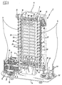
- Figure 1 shows the machine in perspective view;
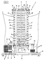
- Figure 2 shows the machine in front view;
- Figure 3 shows the machine in top view.
- With reference to the Figures mentioned the
number 1 indicates in its entirety a machine for processingoptical discs 2, according to the present invention. - The
machine 1 comprises afeeding station 3, awork station 4, anoutlet station 5 storing the processed optical discs and transport means 6 to carry theoptical discs 2 from thefeeding station 3 to thework station 4 and, subsequently, from thework station 4 to theoutlet station 5. - The
work station 4 comprises a plurality ofwork units 7 set parallel to each other and aligned vertically. In the described embodiment, eachwork unit 7 comprises at least a first processing device and at least asecond processing device 8, 9. The first processing device comprises an optical recorder, set to record on virginoptical discs 2 the data read by an optical reader operatively connected with thework units 7 and not shown since it is known in the prior art. The second processing device comprises a serigrapher, set to effect personalisations or to print information on the recordeddiscs 2. - The
feeding station 3 comprises afeeding magazine 10 containing theoptical discs 2 being processed. Thefeeding magazine 10 is constituted by abase feeding disc 11 bearing a series ofloaders 12 distributed circumferentially around a vertical axis of rotation of the disc itself. - The
feeding magazine 10 further comprises afeeder device 13 having a first feeding motor 14 (Figure 3) engaging rotationally aworm gear 15 to make alifting carriage 16 translate thereon. Thelifting carriage 16 presents alifting arm 17 which acts under thediscs 2 of therespective magazine 12 to support them and, when required, to lift them until taking to a pre-determined level thelast disc 2 located at the top of the loader itself. - The
feeding station 3 further comprises a plurality of feeding supports 18 set parallel to each other and able to be aligned vertically each in correspondence with eachwork unit 7. - The
feeding supports 18 are distributed along afeeding conveyor 19 constituted by afeeding belt 20 maintained under tension bycorresponding feeding pulleys 21 engaged on the base structure 1a of themachine 1. Thefeeding belt 21 is essentially placed in a position aside thework station 4 on the side of the recording devices 8. - Through a second feeding motor 22 (Figure 2) operating on one of the
feeding pulleys 21 thefeeding supports 18 are translated according to a stepped motion to be carried cyclically and sequentially in correspondence with thefeeding magazine 10 and, subsequently, in correspondence with thework units 7. - The
feeding supports 18 are distanced from each other according to a measure corresponding to the distance between twoconsecutive work units 7 and each presents agrip pin 23, for the engagement of a respectiveoptical disc 2. - Fastened to the base structure 1a of the
machine 1 is present afeeder arm 24 which is movable between a first position, wherein thefeeder arm 24 is located in proximity to thefeeding magazine 10 to draw thedisc 2 carried to the pre-set level by thelifting arm 17 and a second position, wherein saidfeeding arm 24 is located in proximity to thefeeder conveyor 19 to deposit the disc itself on arespective feeding support 18. The withdrawal and deposit of the discs occurs for instance by means of suction cup elements or equivalent pneumatic means controlled vertically to approach or move away by the feeding arm or through the vertical motion thereof. - Once the supply of
optical discs 2 present in aloader 12 is depleted thebase feeder disc 9 rotates according to a pre-set angle around its own vertical axis, to replace theempty loader 12 with a full loader, thereby guaranteeing a continuous feeding of themachine 1. - The outlet station in turn comprises a plurality of outlet supports 25 positioned parallel to each other and able each to be aligned vertically in correspondence with each
work unit 7. The outlet supports 25 are distanced from each other according to a measure corresponding to the distance between twoconsecutive work units 7, and each presents anoutlet pin 26, for the engagement of a respectiveoptical disc 2. - Similarly to what has been described with reference to the
feeding station 3 the outlet supports 25 are borne by anoutlet conveyor 27 which, by means of anoutlet motor 28, translates the supports themselves cyclically and sequentially according to a stepped motion in correspondence with eachwork unit 7 and, subsequently, in correspondence with anoutlet magazine 29 comprised in theoutlet station 5. - The
outlet conveyor 27 is preferably constituted by anoutlet belt 30 kept under tension by means ofoutlet pulleys 31 engaged on the base structure 1a of themachine 1. Theoutlet pulley 30 is essentially set in a position aside thework station 7 on the side of theserigraphy devices 9. - The
outlet magazine 29 comprises anoutlet base disc 32 having a series ofholders 33 arranged circumferentially around a vertical axis of rotation of the base disc itself. - The
outlet station 5 further comprises at least oneoutlet arm 34 movable between a first position wherein saidoutlet arm 34 is positioned in proximity to theoutlet conveyor 27 to draw the processedoptical discs 2 from the outlet supports 25 and a second position wherein theoutlet arm 34 is positioned in proximity to theoutlet magazine 29 to deposit saiddiscs 2 in theholders 33. - The
discs 2 are drawn and deposited by means of suction cup elements or equivalent pneumatic means as for thefeeding arm 24. - The
outlet arm 34 continues to deposit thediscs 2 into therespective holder 33 until reaching a maximum collection limit, detected by suitable sensors. When this occurs theoutlet base disc 32 rotates around its vertical axis setting anempty holder 33 to co-operate with theoutlet arm 34. - The transport means 6 comprise a plurality of
transport arms 35 each of which, by means at least of onerigid support 36, is associated to one of thework units 7 to draw and deposit simultaneously theoptical discs 2 being processed and/or already processed. - More in detail each
transport arm 35 runs in agroove 37 present on the respectiverigid support 36 to transport theoptical discs 2. Upon command of arespective transfer motor 38, eachtransport arm 35 is movable from a first position to a second position to bring afirst grip head 39 respectively from thework station 4 to thefeeding station 3. When thetransport arm 35 is in the second position, the first grip head 39 grasps the correspondingoptical disc 2. - The
grip heads transport arm 35 can for instance present suction cup elements or pneumatic means functioning essentially like those present on thefeeding arm 24 andoutlet arm 34. - The
transport arm 35 moves again from the second position to the first position to transfer to thework station 4 theoptical disc 2 drawn from thefeeding support 18. - In the embodiment shown, to each
transport arm 35 is also associated at least asecond grip head 40 movable between thework station 4 and theoutlet station 5 following the translation of the transport arm itself between the first position and a third position. - More in particular the
transport arm 35 is set to carry thefirst grip head 39 between thefeeding station 3 and the respective recording device 8 when the arm itself runs between the first position and the second position. Simultaneously, thesecond grip head 40 is carried by the respective recording device 8 to therespective serigraphy device 9. - When the
transport arm 35 moves between the first and the third position thefirst head 39 is carried by the respective recording device 8 to therespective serigraphy device 9. Simultaneously, thesecond grip head 40 is moved from therespective serigraphy device 9 to theoutlet station 5. - According to the present invention, the transport of the
optical discs 2 in themachine 1 occurs according to a method which shall be described better in the following exposition of the functional sequence of the various organs of the machine itself. - Before starting the operating cycle, as well as during the execution thereof, the feeding
magazine 10 is resupplied withloaders 12 carrying therespective discs 2 to be processed. - According to a first phase of the subject method, the feeding
arm 24 grasps adisc 2 from therespective loader 12 to carry it in correspondence with the feedingconveyor 19 and deposit it on therespective feeding support 18. - Once the
optical disc 2 has been deposited onto theaforesaid feeding support 18, the feedingbelt 20 is made to move by one step by thesecond feeding motor 22. - Simultaneously with the movement of the
belt 23 thefeeding arm 18 moves to grasp anadditional disc 2 from the feedingmagazine 10, and subsequently to deposit it onto anew feeding support 18. - The transfer operation of the
optical discs 2 from the feedingmagazine 10 to the feedingconveyor 19 is repeated until a pre-set number of feeding supports 18, for instance corresponding to the number ofwork units 7 present in themachine 1, are provided each with a respectiveoptical disc 2 being processed, placed in correspondence with arespective work unit 7. - According to a second phase of the subject method, when all feeding supports 18 corresponding to the
work units 7 are engaged by thediscs 2, thetransport arms 35 simultaneously translate from the first position to the second position thereby taking the respective first grip heads 39 to draw thediscs 2 from the feedingstation 3. - Subsequently said
transport arms 35 translate towards the first position, in such a way that thediscs 2, upon the action of the respective first grip heads 39, are transferred and operatively inserted each in the respective recording device 8, thereby executing a third phase of the method according to the invention. - As soon as the
discs 2 have been removed from the feedingconveyor 19, the feedingstation 3 starts a new operating cycle whose purpose is to load a new series ofdiscs 2. - In the meantime, the
discs 2 previously removed from theconveyor 19 are processed in thework station 4 to be subsequently removed therefrom, according to fourth phase of the subject method, and unloaded into theoutlet station 5, according to a fifth phase of the method. - More in particular, once processing of the
discs 2 in the recording devices 8 has been completed, eachfirst grip head 39 grasps the recordeddisc 2, whereupon eachtransport arm 35 translates between the first position and the third position. When eachtransport arm 35 is in the third position eachfirst grip head 39 deposits thedisc 2 into theserigraphy device 9. Whilst thediscs 2 are being processed in theserigraphy devices 9 thetransport arms 35 translate again from the third position to the second position grasping by means of the respective first grip heads 39, thenew discs 2 set on the feedingconveyor 19. Eachtransport arm 35 then moves from the second position to the first position inserting thenew disc 2 into the recording device 8. - Once both recording and serigraphy work processes are completed each
transport arm 35 translates from the first position to the third position carrying the recordeddisc 2 in correspondence with theserigraphy device 9 by means of thefirst grip head 39, and theserigraphed disc 2 in correspondence with therespective outlet support 25 by means of thesecond grip head 40. - Once the
serigraphed disc 2 has been deposited on theoutlet support 25, eachtransport arm 35 again reaches the second position to continue the cycle described above, simultaneously transferring anew disc 2 from therespective feeding support 20 to the recording device 8 by means of thefirst grip head 39, as well as the recordeddisc 2, from the respective recording device 8, to theserigraphy device 9 by means of thesecond grip head 40. - When the
discs 2 are deposited on outlet supports 25 theoutlet motor 28 moves step by step theoutlet belt 30 comprised in theoutlet conveyor 27 to make thediscs 2 housed on the outlet supports 26 be drawn sequentially by theoutlet arm 34. - The
outlet arm 34 transfers the disc directly into the outlet magazine depositing them in therespective holder 33. - The operating cycle described above can be executed simultaneously on a maximum number of
discs 2 corresponding to the number ofwork units 7 provided in themachine 1, in order to obtain a high productivity, particularly advantageous in large scale production. - For the production of small lots or samples, the
machine 1 can be operatively set to perform different work cycles, both in regard to the content of the pieces recorded and of the serigraphy, and in regard to execution times. - For example, it can be provided for the first ten
work units 7 to be used to record a given programme on thediscs 2, whilst the remainingwork units 7 record a different programme from the first. - In this case, by appropriately commanding the angular rotation of the
outlet base disc 32, it will be possible to select each time theholder 33 placed in operative engagement with theoutlet arm 34, to cause thediscs 2 containing the same programme to be conveyed onto asame holder 33. - The
machine 1 described above presents a compact structure and reduced size, and therefore is suited to be placed even in small spaces. - The
subject machine 1 also presents relatively reduced realisation and manufacturing costs, and it presents an exceptional operating flexibility which makes it suitable also for producing discs in small numbers. - It should also be noted that the invention solves all problems connected to the production of discs performed by means of manually executed loading and unloading phases, optimising production by means of the simultaneous transport of the discs being processed in the work station, operation which, even with the automation systems of the prior art, was performed individually on each disc thus resulting in very long production times.
- Naturally, the invention thus conceived can be subject to numerous modifications and variations. For instance to each
transport arm 35 can be associated a third grip head, or in any case one grip head more than the number of processing devices pre-set in eachwork unit 7, to transfer the optical discs from the feedingstation 3 to the outlet station 5 (through thevarious processing devices 7, 8) moving only thetransport arm 35 between a first and a second operative position.
Claims (17)
- Machine for processing optical discs comprising:characterised in that:at least one feeding station (3);at least one work station (4) comprising a plurality of work units (7) set parallel to each other and aligned vertically;at least one outlet station (5) storing the processed optical discs (2);transport means (6) to carry the optical discs (2) from the feeding station (3) to the work station (4) and subsequently from the work station (4) to the outlet station (5);said feeding station (3) comprises a plurality of feeding supports (18) set parallel to each other and able to be aligned vertically each in correspondence with each work unit (7);said outlet station (5) comprises a plurality of outlet supports (25) set parallel to each other and able to be aligned vertically each in correspondence with each work unit (7);said transport means (35) comprise a plurality of transport arms (35) each associated to a work unit (7) to grip and deposit simultaneously the optical discs (2) being processed and/or already processed.
- Machine according to claim 1, characterised in that each transport arm (35) is movable between a first position and a second position to carry at least a first grip head (39) from the work station (4) to the feeding station (3).
- Machine according to claim 2, characterised in that said transport arm (35) is movable longitudinally between the first position and a third position to take the first grip head (39) from the work station (4) to the outlet station (5).
- Machine according to claim 2, characterised in that it further comprises at least a second grip head (40) engaged on each transport arm (35) and movable between a work station (4) and the outlet station (5) in the moment wherein the arm itself translates between the first position and the second position.
- Machine according to claim 1, characterised in that said feeding station (3) comprises:at least a feeding magazine (10) containing the optical discs (2) being processed;at least a feeding conveyer (19) carrying said feeding supports (18) and able to be operated step by step to carry cyclically and sequentially the feeding supports (18) in correspondence with the feeding magazine (10) and subsequently in correspondence with the work units (7);at least a feeding arm (24) movable between a first position wherein the feeding arm (24) is situated in proximity to the feeding magazine (10) to draw the discs (2) being processed therefrom and a second position wherein said arm is situated in proximity to the feeding conveyer (19) to deposit said discs (2).
- Machine according to claim 5, characterised in that said feeding supports (18) are distanced from each other by the same interval separating two consecutive work units (7).
- Machine according to claim 1, characterised in that said outlet station (5) comprises:at least one outlet magazine (29) containing the processed optical discs (2);at least one outlet conveyor (27) able to be operated step by step to carry cyclically and sequentially the outlet supports (25) in correspondence with the work units (7) and subsequently in correspondence with the outlet magazine (29);at least one outlet arm (34) movable between a first position wherein the outlet arm (34) is situated in proximity to the outlet conveyer (27) to draw the processed discs (2) on the outlet supports (25) and a second position wherein said arm is situated in proximity to the outlet magazine (29) to deposit said discs (2).
- Machine according to claim 7, characterised in that said outlet supports (25) are distanced from each other by the same interval that separates two consecutive work units (7).
- Machine according to claim 1, characterised in that each transport arm (35) can be operated in motion independently from the other transport arms (35) thereby allowing the machine (1) simultaneously to perform work processes having different execution times.
- Machine according to claim 1, characterised in that said work units (7) comprise at least a first and a second processing device (8, 9) to operate multiple work processes on a same disc.
- Machine according to claim 10, characterised in that said first and second processing devices (8, 9) comprise respectively at least a data recording device (8) and at least a serigraphy device (9).
- Method of transporting discs being processed by a machine according to claim 1, comprising the following phases:characterised in that:a first phase entailing the deposit of at least one optical disc (2) into at least one feeding station (3);a second phase wherein the optical disc (2) is drawn from the feeding station (3);a third phase wherein the optical disc (2) is inserted into at least one work station (4);a fourth phase wherein the optical disc (2) is removed from the work station (4);a fifth phase wherein the optical disc (2) is unloaded into at least one outlet station (5);said first phase entails the disposition of a plurality of optical discs 2 in vertical alignment onto respective feeding supports (18) comprised in the feeding station (3), each optical disc (2) being positioned in correspondence with a respective work station (4);said fifth phase entails the disposition of a plurality of optical discs (2) in vertical alignment onto respective outlet supports (25) comprised in the outlet station (5), each outlet support (25) being located in correspondence with a respective work station (7).
- Method according to claim 12, characterised in that: said second phase entails the simultaneous drawing of said optical discs (2) being processed housed on the respective feeding supports (18);said third phase entails the simultaneous insertion of the optical discs (2) being processed into the work units (7);said fourth phase entails the simultaneous removal of the processed optical discs from the work units (7);said fifth phase entails the simultaneous unloading of the optical discs (2) onto the respective outlet supports (25).
- Method according to claim 12, characterised in that the second and the third phase are executed on the discs (2) being processed simultaneously with the execution of the fourth and fifth phase on the discs (2) already processed.
- Method according to claim 12, characterised in that the optical discs (2) being processed are moved independently from each other from the feeding supports (18) to the work units (7) and subsequently to the outlet supports (25).
- Method according to claim 12, characterised in that said first phase comprises the following sub-phases:setting the feeding supports (18) in mutual alignment;moving simultaneously step by step the feeding supports (18) carrying them sequentially and cyclically in correspondence with at least one feeding magazine (10);transferring the discs (2) individually from the feeding magazine (10) to the respective feeding supports (18) in synchronism with the motion of the outlet supports (25).
- Method according to claim 12, characterised in that after said fifth phase the following sub-phases are performed:moving step by step the outlet supports (25) sequentially and cyclically in correspondence with at least one outlet magazine (29);individually transferring the discs (2) from the outlet supports (25) to the outlet magazine (29) in synchronism with the motion of the outlet supports themselves.
Priority Applications (4)
| Application Number | Priority Date | Filing Date | Title |
|---|---|---|---|
| DE69708108T DE69708108T2 (en) | 1997-11-21 | 1997-11-21 | Optical disk processing machine and method for transporting optical disks during processing |
| EP97830614A EP0918324B1 (en) | 1997-11-21 | 1997-11-21 | A machine for processing optical discs and method of transporting optical discs being processed thereby |
| AT97830614T ATE208531T1 (en) | 1997-11-21 | 1997-11-21 | MACHINE FOR PROCESSING OPTICAL DISCS AND METHOD FOR TRANSPORTING OPTICAL DISCS DURING THEIR PROCESSING |
| CA002242386A CA2242386A1 (en) | 1997-11-21 | 1998-07-06 | An apparatus for processing optical discs and method for transporting optical discs being processed thereby |
Applications Claiming Priority (1)
| Application Number | Priority Date | Filing Date | Title |
|---|---|---|---|
| EP97830614A EP0918324B1 (en) | 1997-11-21 | 1997-11-21 | A machine for processing optical discs and method of transporting optical discs being processed thereby |
Publications (2)
| Publication Number | Publication Date |
|---|---|
| EP0918324A1 EP0918324A1 (en) | 1999-05-26 |
| EP0918324B1 true EP0918324B1 (en) | 2001-11-07 |
Family
ID=8230865
Family Applications (1)
| Application Number | Title | Priority Date | Filing Date |
|---|---|---|---|
| EP97830614A Expired - Lifetime EP0918324B1 (en) | 1997-11-21 | 1997-11-21 | A machine for processing optical discs and method of transporting optical discs being processed thereby |
Country Status (4)
| Country | Link |
|---|---|
| EP (1) | EP0918324B1 (en) |
| AT (1) | ATE208531T1 (en) |
| CA (1) | CA2242386A1 (en) |
| DE (1) | DE69708108T2 (en) |
Families Citing this family (5)
| Publication number | Priority date | Publication date | Assignee | Title |
|---|---|---|---|---|
| US6301217B1 (en) | 1998-06-18 | 2001-10-09 | Bernardini S.R.L. | Apparatus for recording optical disks featuring increased operating speed |
| IT1312476B1 (en) * | 1999-05-11 | 2002-04-17 | Bernardini Srl | LOADING AND UNLOADING STATIONS FOR RECORDING EQUIPMENT OF OPTICAL AND SIMILAR DISCS |
| DE20003125U1 (en) * | 2000-02-21 | 2001-06-28 | Hellmuth, André, 55129 Mainz | Disk duplicator |
| DE10231767C1 (en) * | 2002-07-13 | 2003-08-14 | Krauss Maffei Kunststofftech | Spindle transport and cooling system, for optical disc manufacture, includes four spindles adjusted for simultaneous contact with optically-readable data discs in various formats |
| CN101159150B (en) * | 2006-10-03 | 2010-06-02 | 精工爱普生株式会社 | Media processing device and method for controlling the media processing device |
Family Cites Families (2)
| Publication number | Priority date | Publication date | Assignee | Title |
|---|---|---|---|---|
| JP2559617B2 (en) * | 1988-03-24 | 1996-12-04 | キヤノン株式会社 | Substrate processing equipment |
| US5734629A (en) * | 1995-12-28 | 1998-03-31 | Rimage Corporation | CD transporter |
-
1997
- 1997-11-21 AT AT97830614T patent/ATE208531T1/en not_active IP Right Cessation
- 1997-11-21 EP EP97830614A patent/EP0918324B1/en not_active Expired - Lifetime
- 1997-11-21 DE DE69708108T patent/DE69708108T2/en not_active Expired - Lifetime
-
1998
- 1998-07-06 CA CA002242386A patent/CA2242386A1/en not_active Abandoned
Also Published As
| Publication number | Publication date |
|---|---|
| DE69708108T2 (en) | 2002-03-14 |
| EP0918324A1 (en) | 1999-05-26 |
| ATE208531T1 (en) | 2001-11-15 |
| CA2242386A1 (en) | 1999-05-21 |
| DE69708108D1 (en) | 2001-12-13 |
Similar Documents
| Publication | Publication Date | Title |
|---|---|---|
| CA1307209C (en) | Article handling apparatus for storage and delivery of plural types of articles | |
| JP5295361B2 (en) | Bulk supply of storage devices to a storage device testing system | |
| JPH03177206A (en) | Taking-out/storing method and equipment for article | |
| US5808828A (en) | Installation intended for automatic recording and/or readout onto or from information carriers | |
| JPH0478095B2 (en) | ||
| CN110665827B (en) | Shell-like dental instrument sorting system | |
| JP3844546B2 (en) | Automated apparatus and method for consolidation of packaging products | |
| CN1043031A (en) | disk storage device | |
| ITTO970872A1 (en) | METHOD FOR STACKING PACKAGES OF PLATES OF PRINTED CIRCUITS AND RELATIVE DEVICE FOR LOADING AND UNLOADING OF PACKAGES FOR A MACHINE TOOL. | |
| KR20220051016A (en) | Methods and systems for feeding groups of products to processing units | |
| EP0918324A1 (en) | A machine for processing optical discs and method of transporting optical discs being processed thereby | |
| US5983601A (en) | Machine for the automated packaging of needles and attached sutures | |
| US5549434A (en) | Cassette feed system and method | |
| CN100544573C (en) | Component placement device, component supply device and method | |
| CN112974276A (en) | Material removing and supplementing control method of intelligent production line system of liquid transfer head | |
| US6585100B2 (en) | Arrangement for feeding and/or taking away magazines filled with articles | |
| CN113155035A (en) | Appearance detection device for CNC (computer numerical control) product | |
| US20100290868A1 (en) | System for handling slides | |
| US6205748B1 (en) | Suture package unloading arrangement in a machine for the automated packaging of needles and attached sutures | |
| CN208498997U (en) | Solid State Drive High Speed Automatic Labeling Production Line | |
| CN215373853U (en) | Appearance detection device for CNC (computer numerical control) product | |
| CN214729936U (en) | Electronic component packaging machine | |
| NL1028907C2 (en) | Method and device for supplying and removing carriers with electronic components. | |
| JP3685344B2 (en) | Disc cartridge boxing method and apparatus | |
| WO1994019166A2 (en) | Changing device for manufacturiing information carriers by injection moulding |
Legal Events
| Date | Code | Title | Description |
|---|---|---|---|
| PUAI | Public reference made under article 153(3) epc to a published international application that has entered the european phase |
Free format text: ORIGINAL CODE: 0009012 |
|
| 17P | Request for examination filed |
Effective date: 19980526 |
|
| AK | Designated contracting states |
Kind code of ref document: A1 Designated state(s): AT BE DE DK ES FR GB IE IT NL |
|
| AX | Request for extension of the european patent |
Free format text: AL;LT;LV;MK;RO;SI |
|
| AKX | Designation fees paid |
Free format text: AT BE DE DK ES FR GB IE IT NL |
|
| 17Q | First examination report despatched |
Effective date: 20001228 |
|
| GRAG | Despatch of communication of intention to grant |
Free format text: ORIGINAL CODE: EPIDOS AGRA |
|
| GRAG | Despatch of communication of intention to grant |
Free format text: ORIGINAL CODE: EPIDOS AGRA |
|
| GRAH | Despatch of communication of intention to grant a patent |
Free format text: ORIGINAL CODE: EPIDOS IGRA |
|
| GRAH | Despatch of communication of intention to grant a patent |
Free format text: ORIGINAL CODE: EPIDOS IGRA |
|
| GRAA | (expected) grant |
Free format text: ORIGINAL CODE: 0009210 |
|
| AK | Designated contracting states |
Kind code of ref document: B1 Designated state(s): AT BE DE DK ES FR GB IE IT NL |
|
| PG25 | Lapsed in a contracting state [announced via postgrant information from national office to epo] |
Ref country code: NL Free format text: LAPSE BECAUSE OF FAILURE TO SUBMIT A TRANSLATION OF THE DESCRIPTION OR TO PAY THE FEE WITHIN THE PRESCRIBED TIME-LIMIT Effective date: 20011107 Ref country code: BE Free format text: LAPSE BECAUSE OF FAILURE TO SUBMIT A TRANSLATION OF THE DESCRIPTION OR TO PAY THE FEE WITHIN THE PRESCRIBED TIME-LIMIT Effective date: 20011107 Ref country code: AT Free format text: LAPSE BECAUSE OF FAILURE TO SUBMIT A TRANSLATION OF THE DESCRIPTION OR TO PAY THE FEE WITHIN THE PRESCRIBED TIME-LIMIT Effective date: 20011107 |
|
| REF | Corresponds to: |
Ref document number: 208531 Country of ref document: AT Date of ref document: 20011115 Kind code of ref document: T |
|
| PG25 | Lapsed in a contracting state [announced via postgrant information from national office to epo] |
Ref country code: IE Free format text: LAPSE BECAUSE OF FAILURE TO SUBMIT A TRANSLATION OF THE DESCRIPTION OR TO PAY THE FEE WITHIN THE PRESCRIBED TIME-LIMIT Effective date: 20011121 |
|
| REG | Reference to a national code |
Ref country code: IE Ref legal event code: FG4D |
|
| REF | Corresponds to: |
Ref document number: 69708108 Country of ref document: DE Date of ref document: 20011213 |
|
| REG | Reference to a national code |
Ref country code: GB Ref legal event code: IF02 |
|
| ET | Fr: translation filed | ||
| PG25 | Lapsed in a contracting state [announced via postgrant information from national office to epo] |
Ref country code: DK Free format text: LAPSE BECAUSE OF FAILURE TO SUBMIT A TRANSLATION OF THE DESCRIPTION OR TO PAY THE FEE WITHIN THE PRESCRIBED TIME-LIMIT Effective date: 20020207 |
|
| NLV1 | Nl: lapsed or annulled due to failure to fulfill the requirements of art. 29p and 29m of the patents act | ||
| PG25 | Lapsed in a contracting state [announced via postgrant information from national office to epo] |
Ref country code: ES Free format text: LAPSE BECAUSE OF FAILURE TO SUBMIT A TRANSLATION OF THE DESCRIPTION OR TO PAY THE FEE WITHIN THE PRESCRIBED TIME-LIMIT Effective date: 20020530 |
|
| REG | Reference to a national code |
Ref country code: IE Ref legal event code: MM4A |
|
| PLBE | No opposition filed within time limit |
Free format text: ORIGINAL CODE: 0009261 |
|
| STAA | Information on the status of an ep patent application or granted ep patent |
Free format text: STATUS: NO OPPOSITION FILED WITHIN TIME LIMIT |
|
| 26N | No opposition filed | ||
| PGFP | Annual fee paid to national office [announced via postgrant information from national office to epo] |
Ref country code: FR Payment date: 20021108 Year of fee payment: 6 |
|
| PGFP | Annual fee paid to national office [announced via postgrant information from national office to epo] |
Ref country code: GB Payment date: 20021120 Year of fee payment: 6 |
|
| PG25 | Lapsed in a contracting state [announced via postgrant information from national office to epo] |
Ref country code: GB Free format text: LAPSE BECAUSE OF NON-PAYMENT OF DUE FEES Effective date: 20031121 |
|
| GBPC | Gb: european patent ceased through non-payment of renewal fee |
Effective date: 20031121 |
|
| PG25 | Lapsed in a contracting state [announced via postgrant information from national office to epo] |
Ref country code: FR Free format text: LAPSE BECAUSE OF NON-PAYMENT OF DUE FEES Effective date: 20040730 |
|
| REG | Reference to a national code |
Ref country code: FR Ref legal event code: ST |
|
| PG25 | Lapsed in a contracting state [announced via postgrant information from national office to epo] |
Ref country code: IT Free format text: LAPSE BECAUSE OF NON-PAYMENT OF DUE FEES Effective date: 20051121 |
|
| PGFP | Annual fee paid to national office [announced via postgrant information from national office to epo] |
Ref country code: DE Payment date: 20091119 Year of fee payment: 13 |
|
| REG | Reference to a national code |
Ref country code: DE Ref legal event code: R119 Ref document number: 69708108 Country of ref document: DE Effective date: 20110601 Ref country code: DE Ref legal event code: R119 Ref document number: 69708108 Country of ref document: DE Effective date: 20110531 |
|
| PG25 | Lapsed in a contracting state [announced via postgrant information from national office to epo] |
Ref country code: DE Free format text: LAPSE BECAUSE OF NON-PAYMENT OF DUE FEES Effective date: 20110531 |