EP0917954B1 - Device and method for producing a reference value of a single position in a printing process - Google Patents
Device and method for producing a reference value of a single position in a printing process Download PDFInfo
- Publication number
- EP0917954B1 EP0917954B1 EP98121184A EP98121184A EP0917954B1 EP 0917954 B1 EP0917954 B1 EP 0917954B1 EP 98121184 A EP98121184 A EP 98121184A EP 98121184 A EP98121184 A EP 98121184A EP 0917954 B1 EP0917954 B1 EP 0917954B1
- Authority
- EP
- European Patent Office
- Prior art keywords
- signal
- unit
- speed
- drive shaft
- position reference
- Prior art date
- Legal status (The legal status is an assumption and is not a legal conclusion. Google has not performed a legal analysis and makes no representation as to the accuracy of the status listed.)
- Expired - Lifetime
Links
Images
Classifications
-
- B—PERFORMING OPERATIONS; TRANSPORTING
- B41—PRINTING; LINING MACHINES; TYPEWRITERS; STAMPS
- B41F—PRINTING MACHINES OR PRESSES
- B41F13/00—Common details of rotary presses or machines
- B41F13/004—Electric or hydraulic features of drives
- B41F13/0045—Electric driving devices
-
- B—PERFORMING OPERATIONS; TRANSPORTING
- B41—PRINTING; LINING MACHINES; TYPEWRITERS; STAMPS
- B41F—PRINTING MACHINES OR PRESSES
- B41F13/00—Common details of rotary presses or machines
- B41F13/08—Cylinders
- B41F13/10—Forme cylinders
- B41F13/12—Registering devices
Definitions
- the present invention relates generally to position determination in Printing systems and a control system for a printing press, the Relative positions of drive units in the press controls.
- a conventional printing press usually consists of a series of Printing units.
- the relative positions of drive shafts of these printing units must be accurately regulated to ensure accurate registration of the various To ensure printing units so that errors, such as printing register errors, Web tension errors, web-to-web register errors and / or signature section errors can be prevented. Such errors occur at high Print speeds increased.
- each group of printing units has a drive unit with an input shaft with an output shaft of an electric motor for this Group is connected and driven by this.
- a Speed control unit generates a speed control signal to control the speed of rotation of the Output shaft of the electric motor.
- Other groups of printing units as well as not printing points in the printing press can also have drive units.
- a drive unit of the machine for "master drive” is determined, the one Receives signal that the desired speed of through the printing press shows the running paper web. This signal of the desired speed is sent to the Speed control element of the master drive for controlling the speed of the Drive shaft of the master drive sent. Signals the actual speed and position the drive shaft of the master drive are displayed on the others, as “slave drives” designated drive units transmitted.
- the speed controller of everyone Follower unit sends a speed control signal based on the actual position of the Drive shafts of the slave drives and the drive shaft of the master drive are based on the Electric motor of the slave drive, which causes the drive shaft of each Follower follows the speed and position of the drive shaft of the master drive.
- the drive shaft of each slave drive unit is in the same position and has the same speed as the drive shaft of the master drive unit.
- DE 41 37 979 describes a drive for a printing press with several Printing units, the individual printing units or printing unit groups are mechanically decoupled from each other, each printing unit or each Printing unit group is assigned a drive motor and being on each Printing unit or at each printing unit group a device for speed and / or Rotation angle determination is arranged. It is also a device for Angle control is provided, which is a permissible angular deviation of the individual printing units or printing unit groups from a given Angle setpoint dimensioned such that it at least in the angular position at handing over a sheet is minimal.
- the respective Angular position of two printing units fed to a microcomputer which continue from a setpoint specification a speed setpoint and one Receives the angle setpoint at which the sheet transfer is to take place, the Microcomputer based on an angular difference between the given Angle setpoint and the angular positions of the printing units torque setpoints calculated such that the permissible angular deviation of the respective Printing units of the specified target value at the sheet transfer is minimal.
- DD 115 069 discloses a method for starting register control on printing presses with several printing units, whereby the position of elements, for example, gears on at least two printing units by pulse generators is sampled, the phase position or phase shift of a pulse opposite the other pulse, the reference pulse, electronically according to size and direction is determined and the determined value for adjusting an actuator is evaluated becomes.
- a synchronous controller includes normally a resolver to the angular position of the drive shaft of the Convert slave drive into an electrical output signal. The position of the The slave drive shaft relative to the position of the master drive shaft will then be in correspondence of the electrical output signal generated by the synchronous regulator.
- Control devices with control compensation such as "Forced control”, “Speed setpoint” and “dp / dt pilot control” are also known.
- a "Type-3" controller can be used, the one Position error signal (i.e., a difference in the positions of the slave shaft and the master drive shaft) double integrated.
- a regulator is issued in US 5,049,798 on September 17, 1991.
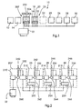
- Fig. 1 shows a conventional printing machine 10 with feed mechanisms 12 and 14, one Group 207 of printing units 200 - 206 and a group 23 of printing units 16 - 22, a dryer 24, cooling units 25 and 26 and folding units 28 and 30.
- Each of the Printing unit groups 207 and 23 and folding units 28 and 30 have one Drive unit. From a master reference signal source 32 a signal, i. H. on Speed command signal generated that the drive unit of group 207 a displays the desired press speed.
- the drive unit of the Group 207 is designated as the master drive unit.
- Those belonging to group 23 other drive units and the folding units 28 and 30 are used as subsequent printing units designated that follow the position and speed of the master printing unit.
- FIGS Groups 207 and 23 shows details regarding the internal components of the drive units in FIGS Groups 207 and 23 and the folding units 28 and 30 and connections between the Drive units and the control reference signal source 32.
- the Control reference signal source 32 incoming speed command signal in Speed control element 210 of the master drive unit entered in group 207, to control the speed of motor 260.
- the speed command signal can be an analog or a digital signal.
- a position encoder 230 determines the Actual position value of a drive shaft 240, which is from the motor 260 of the master drive unit is driven.
- the Position encoder 230 since the position information output from the position encoder 230 can be used to determine speed information, the Position encoder 230 alternatively also an actual value to the Send speed controller 210 back to ensure that the actual speed the drive shaft 240 of the master drive unit of the desired one Speed corresponds.
- the speeds and positions of the drive shafts 242-246 of the Follower units are controlled to match speed and position the drive shaft 240 of the master drive unit are adapted. This is through Using the speed of the drive shaft 240 of the master drive unit together with the feedback regarding the positions of the drive shafts 242-248 of the slave drive units relative to the position of the drive shaft 240 of the Master drive unit achieved.
- the slave drive units have motors 262-266 that are Drive drive shafts 242-246.
- Position encoders 232-236 determine the actual positions of the drive shafts 242-246 and send corresponding feedback signals to Controllers 222-226, which indicate the specific positions.
- that of the Position encoders 232-236 produce information for determining both the Speeds as well as the positions of the corresponding drive shafts 242-246 be used.
- the output signal generated by the position encoder 230 that the Indicates actual position of the drive shaft 240 of the master drive unit is considered a Reference position signal to the controllers 222-226 of the slave drive units of the Printing unit group 23 and sent to the folding units 28 and 30, as shown in Fig. 2.
- the controllers 222-226 compare the output signal of the position encoder 230 Master drive unit with the output signals of the position encoder 232-236 and send on the basis of this comparison command signals to the speed controllers 212-216, to control the speed of motors 262-266 such that the Drive shafts 242-246 of the slave drive units of the speed and position of the Drive shaft 240 follow the master drive unit.
- this produces one Impulse for every angular increment of the rotating drive shaft 240 Master drive. So while the drive shaft is rotating, the Position encoder 230 a stream of pulses.
- the position encoder 230 Number of pulses generated during a time interval indicates by what amount the drive shaft 240 has changed position during this time interval.
- the Average speed during the time interval can be determined effortlessly by the value of the position change by the duration of the time interval is divided.
- the angular increase corresponding to a pulse is fixed so that the Position encoder 230 generates 2,048 pulses during each complete revolution.
- the position encoder 230 is monitored and the pulses generated by it become counted by means of a counter, not shown.
- the counter usually jumps to Completion of one turn back to zero after counting up to 2,048. In some designs there is a different number of pulses per revolution decisive and in other versions the counter jumps less frequently than after to zero every revolution.
- the position encoders 232-236 are the same like the position encoder 230.
- the positions of the encoders 230-236 can be synchronized by simultaneously setting the corresponding counter to zero be reset, e.g. B. when the paper web with slower and constant speed through the printing press.
- the meters are inside or near the corresponding position encoder.
- controllers 222-226 for synchronizing the speeds and Positions of the drive shafts of the slave drive units with those of the Drive shaft 240 of the master drive unit are designed, they can not be used are used for problems caused by mechanical malfunctions or control errors on the Drive shaft 240 of the master drive unit arise. Such control errors will arise the. Transfer drive units and there is a tendency that these errors to repeat. Thus, a control error on the master drive shaft can affect the function of the Very badly affect slave drive units. In the event of major faults, the controller performance interrupted or endangered, so that problems in printing, e.g. B. by Register errors can occur.
- the present invention relates to a method and an apparatus which make it possible to trouble-free speed and position reference signals on drive units in one Printing machine, e.g. B. printing units to send.
- a device for controlling the printing process of a printing press a first and at least a second drive unit with a respective motor and one respective drive shaft; a first and at least a second position encoder, which each determine the actual position of the respective drive shaft and at least one Generate position encoder signal; a first and at least a second Speed control unit which control the speed of the respective drive shaft; and
- a first controller is characterized in that the device is a single position reference value unit having at least one single position reference signal based on the desired printing press speed that is generated free by the printing operation triggered disturbances, and sends to the first and at least second controller, the Controller to the respective speed control unit on the single position reference signal and send a control signal based on the respective position encoder signal, and that the Single position reference signal and the position encoder signals each a number of pulses include.
- a single position reference value unit receives a signal that the displays the desired speed of a web running through the printing press.
- the Single position reference value unit generates signals that have a correct reference speed and represent an error-free reference position and which the printing press drive units, for.
- the same Reference signals can be sent to all drive units. Alternatively, separate reference signals can be used be generated for each drive unit and between the individual, for the different Drive signals generated by reference signals can cause inaccuracies Error correction circuits are corrected.
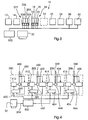
- Fig. 3 shows an embodiment of a printing press, in which elements that with those of the printing press shown in Fig. 1 are identical to the same Reference signs have been identified. According to the embodiments of the present invention is not one of the printing units of a printing press Leitdruckwerk marked. As shown in Fig. 3, is a single position reference value unit 500 provided by a master reference signal source 32 a Received signal representing the desired printing press speed and a Send single position reference signal to each printing unit. In contrast to that in the 1 and 2, the printing presses shown have each of the printing units 200-206 and 16-22 and each of the folding units 28 and 30 has a separate drive unit.
- FIGS. 3 and 4 is a drive unit for has any printing unit, it is self-evident to the person skilled in the art that the invention also in a printing press with only one drive unit for all printing units or for any group of printing units can be realized.
- a single drive unit for a group of printing units can be controlled in the same way as one Drive unit for a single printing unit in the described here Embodiments is controlled.
- Fig. 4 shows details of the printing machine of Fig. 3, i.e. H. internal components of the Printing units 200-206 and connections between these printing units, the Single position reference value unit 500. and the master reference signal source 32. In contrast to the components shown in FIG.
- the Drive unit 2 is the drive unit for the printing unit 200 equipped with a regulator 420; thus the inner construction is this Drive unit the same as that shown in the other printing units 202-206 Drive units.
- Each of the controllers 420-426 in the printing units 200-206 receives this Single position reference signal from the single position reference value unit 500.
- the Single position reference signal can be an analog or a digital signal.
- the speeds and positions of the drive shafts 440-446 of the drive units are controlled so that they are displayed by the single position reference signal Adjust the reference speed and position using the Reference speed, along with feedback regarding the positions of the Drive shafts 440-446 of the drive units relative to the reference position.
- the drive units have motors 460-466 which the Drive drive shafts 440-446.
- Position encoders 430-436 determine the actual positions of the drive shafts 440-446 and send corresponding feedback signals to controllers 420-426, which indicate the particular positions.
- the information output from position encoders 430-436 for both determination the speeds as well as the positions of the corresponding ones Drive shafts 440-446 can be used.
- the controllers 420-426 compare that Single position reference signal with the output of position encoders 430-436 and transmit based on this comparison command signals to the Speed control units 410-416 for controlling the speed of the Motors 460-466, so that the drive shafts 440-446 of the drive units of the by the Single position reference signal follow displayed speed and position. Consequently the drive shafts 440-446 are affected by temporary mechanical disturbances in the Print operation not affected.
- the printing units 16-22 and the folding units 28 and 30 are of the same configuration and offer the same advantages.
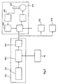
- Fig. 5 shows a second embodiment of the invention with an exemplary internal configuration of the single position reference value unit 500 which one Vibration generator 502, a divider / multiplier 504 and a filter / amplifier device 506 includes.
- the vibrator 502 generates one Time signal corresponding to that received from the control reference signal source 32 Signal that represents the desired press speed, divided or is multiplied.
- the filter / amplifier device 506 filters noise from the Divider / multiplier 504 output signal and sends the resultant Single position reference signal to the controllers of the printing units.
- the filter / amplifier device 506 also amplifies the signal in each of the users desired way so that it is compatible with the controls in the printing units.
- the Single position reference value unit 500 can be realized by only electronic components are used, they can be a solid state device or be an analog device.
- Each pulse of that output from the single position reference value unit 500 Single position reference signal represents an angular increase by which there is a Drive shaft must move.
- the angle increase has a predetermined value. Consequently indicates the number of times in the single position reference signal within a time interval impulses indicate a change in the reference position during this time interval and the frequency of the pulses indicates a reference speed or Reference angular velocity.
- FIG. 5 shows in the printing unit 200 a counter / scanner 508 which is connected to the controller 420 and to position encoder 430 and can be used to adjust the Processing ability of the controller 420 to supplement and / or information from To provide position encoders 430 in a more useful form.
- the counter / scanner 508 can, for example, generate a signal that corresponds to the number of position increases which the drive shaft 440 has moved during a time interval, i. H. the Displays the number of position changes during the time interval.
- Controller 420 includes a counter (not shown) that is used by the single position reference value unit 500 received impulses counts with those of the Counter / sampler 508 counted pulses can be compared to one possible Phase difference between the reference position and the position of the drive shaft 440 determine.
- the counter can also be inside the divider / multiplier 504 mounted in the single position reference value unit 500 be so that the signal output of unit 500 is a pulse number.
- Controller 420 can also received a delay compensation signal to unwanted To compensate for signal delays or inaccuracies occurring in the system.
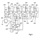
- Fig. 6 shows a third embodiment of the invention, the configuration of the Single position reference value unit 600 which includes one motor 668, one Drive shaft 648, a position encoder 638, a speed control unit 618 and includes a controller 628.
- the internal construction of the single position reference unit 600 is similar to that shown in the printing units 200-206 of FIG. 4, but with a few differences.
- the drive shaft 648 is not one of the Processes in the printing press and therefore no undesirable mechanical malfunctions in the operation of the printing press, for example Blanket washes, subjected.
- the drive shaft 648 can e.g. B. with a Operation process (not shown) connected, the straightforward, predictable Has behavioral characteristics and is free from transition disorders, the problems could cause in machine operation.
- controller 628 receives that desired speed command signal indicating printing press speed from the lead reference signal source.
- this is from position encoder 638 output signal is the single position reference signal which is sent to the controllers 420-426 Printing units 200-206 is sent.
- Motor 668 can operate independently of others in the Printing machine used motors can be selected. For example, the Motor 668 can be smaller than motors 460-466 and an auxiliary motor.
- the controller 628 of the single position reference value unit 600 controls the Speed control unit 618 in that by means of a Speed feedback the speed of the drive shaft 648 as precise as possible is maintained to indicate the desired speed.
- regulators 420-426 regulate the respective Speed control units of the printing units 200-206 in such a way that the Drive shafts 440-446 the speed and position of drive shaft 648 accurately consequences.
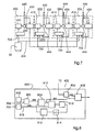
- Fig. 7 shows a fourth embodiment of the invention.
- the unit position reference value unit actually consists of components that are within the regulator located, and from connections between the controllers. That is, each of the controls internally generates a single position reference signal which is based on the Speed command signal from the master reference signal source 32 based.
- each Controller becomes the single position reference signal with the drive shaft speed and the position information obtained from the position encoder of the corresponding one Printing unit is generated, compared. Based on this comparison, the Regulator sends a command signal to a corresponding speed control unit is input so that the drive shaft by the single position reference signal displayed reference speed and position follows.
- printing unit 200 is selected as a standard unit and that of whose position encoder 430 output signal 700 is from everyone else Printing units used as a standard to which the single position reference signal each of the printing units is periodically adjusted. According to the embodiments the single position reference signals are corrected at one time or standardized if the printing unit chosen as standard does not suffer from transitional faults is influenced.
- This concept can also be used, for example, when the invention is in an existing printing press is integrated, which is due to original structural Restrictions do not apply to the same single position reference signal on all their drive units can transmit.
- FIG. 8 shows the internal construction of controller 822 of FIG. 7.
- a vibrator 800 generates a timing signal in a manner similar to that in FIG. 5 Single position reference value unit 500 shown.
- the time signal is sent to a divider / multiplier unit 802 sent the the time signal that is on the by the Routing reference signal source 32 received via line 304 Speed command signal based, divided or multiplied, and that too Pulses of the divided or multiplied time signal counts.
- a Signal setting unit 804 filters noise from the pulse count signal from the divider / multiplier 802 is output, and amplifies the signal accordingly.
- the Signal setting unit 804 can also set the signal so that it matches the Standard signal 700 is synchronized.
- the one output from the signal setting unit 804 Signal is a single position reference signal for the print engine 202 and is turned on Position register 808 sent.
- Position register 808 also receives a signal from counter 806; this signal indicates the number of pulses detected by the Received counter 806 from position encoder 432.
- the counter 806 may receive a signal generate the number of position increments by which the drive shaft 442 has moved during a time interval, d. H. the number of position changes displays during the time interval.
- Position register 808 compares that from counter 806 and from Signal setting unit 804 sent signals.
- the signals represent a change the position of the drive shaft 442 and a change in the reference position during a Time interval and also show the reference speed and the speed the drive shaft 442. Based on this comparison, this creates Position register 808 a command signal that is sent to the speed control unit 412 is sent as is more well known according to the general principles Control functions take place and for example in the controller 22 of that shown in FIG. 2 Printing machine of the prior art is realized.
- An exemplary implementation of a circuit to correct or Standardizing the single position reference signal generated in controller 822 a counter 818, a comparator 812, an error detector 810, one Error compensator 814 and a correction value limiter 816.
- counter 818 functions in the same way as counter / scanner 508 in FIG. 5 and counter 806.
- the printing group 200 is selected as the standard printing group.
- counter 818 detects the pulses and received from the position encoder 430 of the standard printing unit 200 generates a signal representing the number of position increments by which the Drive shaft 440 has moved during a time interval, i.e. the number of Displays changes in position during the time interval.
- the signal output from counter 818 and the single position reference signal from of the signal setter 804 are input to the comparator 812 which is the compares the two signals and generates an error signal on the basis of this comparison.
- the signal output by the comparator 812 is fed into the error detector 810 entered the presence and magnitude of the error between (a) the output signal counter 818, i. H. the position and speed of the drive shaft 440 the standard print engine 200, as indicated by the position encoder 430, and (b) the Reference speed and position as determined by the signal setting unit 804 output single position reference signal shown, detected.
- the error detector 810 generates a signal indicating the particular error and the signal is converted into a Error compensator 814 input, which generates a control signal, which the Signal setter 804 causes the single position reference signal to be corrected or to the position and speed of the drive shaft 440 of the Standard printing unit 200 to adapt.
- a correction value limiter 816 can be used with the Error compensator 814 and the signal adjuster 804 are connected to the Correction process by restricting the output signal of the error compensator 814 slow it down.
- controller 822 can Contain counter 806 and position register 808 and an output signal from Position encoder 432 and another output signal from the Receive signal setter 804.
- Components like that Vibration generator 800, the divider / multiplier 802, the Signal setting unit 804, the comparator 812, the error detector 810, the Error compensator 814, correction value limiter 816 and counter 818 can be on can be arranged anywhere as long as they remain correctly connected and the output of the signal setting unit 804 to the controller 822, the routing reference signal 304 to the Divider / multiplier 802 passes and the standard position encoder signal 700 to counter 818.
- the other printing units 204, 206 can be of the same construction and in be operated in the same way as the printing unit 202. If the configuration of the FIG. 8, for example, for the prior art printing machine shown in FIG. 2 is to be used, the printing group 23 and the folding units 28 and 30 2 may have the same construction as the printing unit 202.
Description
Die vorliegende Erfindung betrifft im allgemeinen die Positionsbestimmung in Drucksystemen und ein Steuersystem für eine Druckmaschine, das Relativpositionen von Antriebseinheiten in der Druckmaschine regelt.The present invention relates generally to position determination in Printing systems and a control system for a printing press, the Relative positions of drive units in the press controls.
Da von herkömmlichen Rollenrotationsdruckmaschinen, z. B. von den für den Zeitungsdruck verwendeten Maschinen, traditionell kein Druck von hoher Qualität oder Bildschärfe erwartet wurde, ist in der Druckindustrie die Toleranzschwelle für den Druckqualitätsverlust relativ hoch gewesen. Jedoch ist es in zunehmendem Maße erwünscht, die Qualität und Bildschärfe von Druckprodukten zu verbessern, so daß ein Bedarf an Druckmaschinen besteht, die Druckprodukte von hoher Qualität und Bildschärfe liefern können. Normalerweise geht mit der Produktion von Produkten in hoher Qualität eine Verringerung der Druckgeschwindigkeit einher. Dennoch ist es in der Druckindustrie erwünscht, daß Druckmaschinen mit hohen Geschwindigkeiten betrieben werden können. Es hat sich jedoch herausgestellt, daß es eine sehr schwierige Aufgabe ist, den Erfordernissen für Qualität, Bildschärfe und Geschwindigkeit gleichzeitig gerecht zu werden.Because of conventional web-fed rotary printing presses, e.g. B. from for Machines used in newspaper printing, traditionally no high quality printing or Sharpness was expected, the tolerance threshold for the printing industry Print quality loss has been relatively high. However, it is increasing desired to improve the quality and sharpness of printed products so that a There is a need for printing presses that produce high quality and printed products Can deliver sharpness. Usually goes in with the production of products high quality is accompanied by a reduction in printing speed. Still, it's in the printing industry desires that printing presses at high speeds can be operated. However, it turned out to be a very difficult one The task is to meet the requirements for quality, sharpness and speed to do justice at the same time.
Eine herkömmliche Druckmaschine besteht normalerweise aus einer Reihe von Druckwerken. Die Relativpositionen von Antriebswellen dieser Druckwerke müssen akkurat geregelt werden, um eine genaue Registerhaltigkeit der verschiedenen Druckwerke zu gewährleisten, so daß Fehler, wie Druckregisterfehler, Bahnspannungsfehler, Bahn-zu-Bahn-Registerfehler und/oder Signaturabschnittfehler verhindert werden können. Solche Fehler treten nämlich bei hohen Druckgeschwindigkeiten verstärkt auf.A conventional printing press usually consists of a series of Printing units. The relative positions of drive shafts of these printing units must be accurately regulated to ensure accurate registration of the various To ensure printing units so that errors, such as printing register errors, Web tension errors, web-to-web register errors and / or signature section errors can be prevented. Such errors occur at high Print speeds increased.
In gewissen Druckmaschinen besitzt jede Gruppe von Druckwerken eine Antriebseinheit mit einer Antriebswelle, die mit einer Abtriebswelle eines Elektromotors für diese Gruppe verbunden ist und von dieser angetrieben wird. Eine Geschwindigkeitssteuereinheit erzeugt ein Geschwindigkeitssteuersignal zur Steuerung der Drehgeschwindigkeit der Abtriebswelle des Elektromotors. Weitere Gruppen von Druckwerken sowie auch nicht druckende Stellen in der Druckmaschine können ebenfalls Antriebseinheiten besitzen. Gewöhnlich wird eine Antriebseinheit der Maschine zum "Leitantrieb" bestimmt, der ein Signal empfängt, das die gewünschte Geschwindigkeit der durch die Druckmaschine laufenden Papierbahn anzeigt. Dieses Signal der gewünschten Geschwindigkeit wird an das Geschwindigkeitssteuerorgan des Leitantriebs zur Steuerung der Geschwindigkeit der Antriebswelle des Leittantriebs gesandt. Signale, die die Ist-Geschwindigkeit und Position der Antriebswelle des Leitantriebs anzeigen, werden auf die anderen, als "Folgeantriebe" bezeichnete Antriebseinheiten übertragen. Das Geschwindigkeitssteuerorgan einer jeden Folgeantriebseinheit sendet ein Geschwindigkeitssteuersignal, das auf der Ist-Position der Antriebswellen der Folgeantriebe und der Antriebswelle des Leitantriebs beruht, an den Elektromotor des Folgeantriebs, was bewirkt, daß die Antriebswelle des jeweiligen Folgeantriebs der Geschwindigkeit und Position der Antriebswelle des Leitantriebs folgt. Im idealen Fall ist die Antriebswelle jeder Folgeantriebseinheit in der gleichen Position und hat die gleiche Geschwindigkeit wie die Antriebswelle der Leitantriebseinheit.In certain printing presses, each group of printing units has a drive unit with an input shaft with an output shaft of an electric motor for this Group is connected and driven by this. A Speed control unit generates a speed control signal to control the speed of rotation of the Output shaft of the electric motor. Other groups of printing units as well as not printing points in the printing press can also have drive units. Usually a drive unit of the machine for "master drive" is determined, the one Receives signal that the desired speed of through the printing press shows the running paper web. This signal of the desired speed is sent to the Speed control element of the master drive for controlling the speed of the Drive shaft of the master drive sent. Signals the actual speed and position the drive shaft of the master drive are displayed on the others, as "slave drives" designated drive units transmitted. The speed controller of everyone Follower unit sends a speed control signal based on the actual position of the Drive shafts of the slave drives and the drive shaft of the master drive are based on the Electric motor of the slave drive, which causes the drive shaft of each Follower follows the speed and position of the drive shaft of the master drive. In the ideal case, the drive shaft of each slave drive unit is in the same position and has the same speed as the drive shaft of the master drive unit.
DE 41 37 979 beschreibt einen Antrieb für eine Druckmaschine mit mehreren Druckwerken, wobei die einzelnen Druckwerke oder Druckwerksgruppen mechanisch voneinander entkoppelt sind, wobei jedem Druckwerk bzw. jeder Druckwerksgruppe ein Antriebsmotor zugeordnet ist und wobei an jedem Druckwerk bzw. an jeder Druckwerksgruppe eine Vorrichtung zur Drehzahlund/oder Drehwinkelermittlung angeordnet ist. Es ist weiterhin eine Vorrichtung zur Winkelregelung vorgesehen, die eine zulässige Drehwinkelabweichung der einzelnen Druckwerke bzw. Druckwerksgruppen von einem vorgegebenen Winkelsollwert derart bemisst, dass sie zumindest bei der Drehwinkelstellung, bei der eine Bogenübergabe erfolgt, minimal ist. Dabei wird die jeweilige Winkelstellung zweier Druckwerke einem Mikrorechner zugeführt, welcher weiterhin von einer Sollwertvorgabe einen Drehzahlsollwert und einen Winkelsollwert erhält, bei dem die Bogenübergabe stattfinden soll, wobei der Mikrorechner anhand einer Winkeldifferenz zwischen dem vorgegebenen Winkelsollwert und den Winkelstellungen der Druckwerke Drehmomentsollwerte berechnet, derart, dass die zulässige Drehwinkelabweichung der jeweiligen Druckwerke von dem vorgegebenen Sollwert bei der Bogenübergabe minimal ist.DE 41 37 979 describes a drive for a printing press with several Printing units, the individual printing units or printing unit groups are mechanically decoupled from each other, each printing unit or each Printing unit group is assigned a drive motor and being on each Printing unit or at each printing unit group a device for speed and / or Rotation angle determination is arranged. It is also a device for Angle control is provided, which is a permissible angular deviation of the individual printing units or printing unit groups from a given Angle setpoint dimensioned such that it at least in the angular position at handing over a sheet is minimal. The respective Angular position of two printing units fed to a microcomputer, which continue from a setpoint specification a speed setpoint and one Receives the angle setpoint at which the sheet transfer is to take place, the Microcomputer based on an angular difference between the given Angle setpoint and the angular positions of the printing units torque setpoints calculated such that the permissible angular deviation of the respective Printing units of the specified target value at the sheet transfer is minimal.
DD 115 069 offenbart ein Verfahren zur Anfahrregisterregelung an Druckmaschinen mit mehreren Druckwerken, wobei laufend die Stellung von Elementen, beispielsweise Zahnrädern an wenigstens zwei Druckwerken durch Impulsgeber abgetastet wird, die Phasenlage bzw. Phasenverschiebung eines Impulses gegenüber dem anderen Impuls, dem Bezugsimpuls, nach Größe und Richtung elektronisch ermittelt wird und der ermittelte Wert zur Verstellung eines Stellgliedes ausgewertet wird.DD 115 069 discloses a method for starting register control on printing presses with several printing units, whereby the position of elements, for example, gears on at least two printing units by pulse generators is sampled, the phase position or phase shift of a pulse opposite the other pulse, the reference pulse, electronically according to size and direction is determined and the determined value for adjusting an actuator is evaluated becomes.
Es gibt viele Arten von Regeleinrichtungen, um die Position der Antriebswelle eines Folgeantriebs relativ zur Position der Antriebswelle eines Leitantriebs zu regeln, wie beispielsweise phasenstarre Regler und Gleichlaufregler. Ein Gleichlaufregler umfaßt normalerweise einen Drehmelder, um die Winkelposition der Antriebswelle des Folgeantriebs in ein elektrisches Ausgangssignal umzuwandeln. Die Position der Folgeantriebswelle relativ zur Position der Leitantriebswelle wird dann in Entsprechung des vom Gleichlaufregler erzeugten elektrischen Ausgangssignals geregelt. Regeleinrichtungen mit einem Steuerungsausgleich, wie beispielsweise "Zwangssteuerung", "Drehzahl-Soll-Wert" und "dp/dt Vorsteuerung" sind ebenfalls bekannt. Außerdem kann auch ein "Typ-3" Regler verwendet werden, der ein Positionsfehlersignal (d. h. einen Differenzwert in den Positionen der Folgeantriebswelle und der Leitantriebswelle) doppelt integriert. Solch ein Regler ist in US 5,049,798, erteilt am 17. September 1991, beschrieben. There are many types of control devices to determine the position of the drive shaft To control the slave drive relative to the position of the drive shaft of a master drive, such as for example phase-locked controllers and synchronous controllers. A synchronous controller includes normally a resolver to the angular position of the drive shaft of the Convert slave drive into an electrical output signal. The position of the The slave drive shaft relative to the position of the master drive shaft will then be in correspondence of the electrical output signal generated by the synchronous regulator. Control devices with control compensation, such as "Forced control", "Speed setpoint" and "dp / dt pilot control" are also known. In addition, a "Type-3" controller can be used, the one Position error signal (i.e., a difference in the positions of the slave shaft and the master drive shaft) double integrated. Such a regulator is issued in US 5,049,798 on September 17, 1991.
Fig. 1 zeigt eine herkömmliche Druckmaschine 10 mit Einzugswerken 12 und 14, eine
Gruppe 207 von Druckwerken 200 - 206 und eine Gruppe 23 von Druckwerken 16 - 22,
einen Trockner 24, Kühleinheiten 25 und 26 und Falzeinheiten 28 und 30. Jede der
Druckwerksgruppen 207 und 23 und Falzeinheiten 28 und 30 besitzt eine
Antriebseinheit. Von einer Leit-Bezugssignalquelle 32 wird ein Signal, d. h. ein
Geschwindigkeitsbefehlssignal erzeugt, das der Antriebseinheit der Gruppe 207 eine
gewünschte Druckmaschinengeschwindigkeit anzeigt. Die Antriebseinheit der
Gruppe 207 wird als Leitantriebseinheit designiert. Die zur Gruppe 23 gehörenden
anderen Antriebseinheiten und die Falzeinheiten 28 und 30 werden als Folgedruckwerke
designiert, die der Positition und Geschwindigkeit des Leitdruckwerks folgen.Fig. 1 shows a
Fig. 2 zeigt Details bezüglich der inneren Komponenten der Antriebseinheiten in den
Gruppen 207 und 23 und den Falzeinheiten 28 und 30 und Verbindungen zwischen den
Antriebseinheiten und der Leitbezugssignalquelle 32. Insbesondere wird das von der
Leitbezugssignalquelle 32 kommende Geschwindigkeitsbefehlssignal in ein
Geschwindigkeitssteuerorgan 210 der Leitantriebseinheit in der Gruppe 207 eingegeben,
um die Geschwindigkeit des Motors 260 zu steuern. Das Geschwindigkeitsbefehlssignal
kann ein analoges oder ein digitales Signal sein. Ein Positionskodierer 230 bestimmt den
Positions-Ist-Wert einer Antriebswelle 240, die vom Motor 260 der Leitantriebseinheit
angetrieben wird. Da die vom Positionskodierer 230 ausgegebene Positionsinformation
zur Ermittlung von Geschwindigkeitsinformation benutzt werden kann, so kann der
Positionskodierer 230 alternativ auch einen Ist-Wert an das
Geschwindigkeitssteuerorgan 210 zurücksenden, um zu gewährleisten, daß die Ist-Geschwindigkeit
der Antriebswelle 240 der Leitantriebseinheit der gewünschten
Geschwindigkeit entspricht.2 shows details regarding the internal components of the drive units in FIGS
Die Geschwindigkeiten und Positionen der Antriebswellen 242-246 der
Folgeantriebseinheiten werden derart gesteuert, daß sie der Geschwindigkeit und Position
der Antriebswelle 240 der Leitantriebseinheit angepaßt sind. Dies wird durch
Verwendung der Geschwindigkeit der Antriebswelle 240 der Leitantriebseinheit
zusammen mit der Rückmeldung bezüglich der Positionen der Antriebswellen 242-248
der Folgeantriebseinheiten relativ zur Position der Antriebswelle 240 der
Leitantriebseinheit erzielt.The speeds and positions of the drive shafts 242-246 of the
Follower units are controlled to match speed and position
the
Wie in Fig. 2 gezeigt, weisen die Folgeantriebseinheiten Motoren 262-266 auf, die die
Antriebswellen 242-246 antreiben. Positionskodierer 232-236 bestimmen die Ist-Positionen
der Antriebswellen 242-246 und senden entsprechende Rückmeldesignale an
Regler 222-226, die die bestimmten Positionen anzeigen. Wie oben bezüglich des
Positionskodierers 230 der Leitantriebseinheit erwähnt, kann die von den
Positionskodierern 232-236 erzeugte Information für die Bestimmung sowohl der
Geschwindigkeiten als auch der Positionen der korrespondierenden Antriebswellen 242-246
verwendet werden. Das vom Positionskodierer 230 erzeugte Outputsignal, das die
Ist-Position der Antriebswelle 240 der Leitantriebseinheit anzeigt, wird als ein
Bezugspositionssignal an die Regler 222-226 der Folgeantriebseinheiten der
Druckwerksgruppe 23 und an die Falzeinheiten 28 und 30 gesandt, wie in Fig. 2 gezeigt.
Die Regler 222-226 vergleichen das Ausgangssignal des Positionskodierers 230 der
Leitantriebseinheit mit den Ausgangssignalen der Positionskodierer 232-236 und senden
auf der Basis dieses Vergleichs Befehlssignale an die Geschwindigkeitssteuerorgane 212-216,
um die Geschwindigkeit der Motoren 262-266 derart zu steuern, daß die
Antriebswellen 242-246 der Folgeantriebseinheiten der Geschwindigkeit und Position der
Antriebswelle 240 der Leitantriebseinheit folgen.As shown in FIG. 2, the slave drive units have motors 262-266 that are
Drive drive shafts 242-246. Position encoders 232-236 determine the actual positions
of the drive shafts 242-246 and send corresponding feedback signals to
Controllers 222-226, which indicate the specific positions. As above regarding the
Gemäß einem Ausführungsbeispiel des Positionskondierers 230 erzeugt dieser einen
Impuls für jeden Winkelzuwachs der sich drehenden Antriebswelle 240 der
Leitantriebseinheit. Während sich also die Antriebswelle dreht, erzeugt der
Positionskodierer 230 einen Strom von Impulsen. Die vom Positionskodierer 230
während eines Zeitintervalls erzeugte Anzahl von Impulsen deutet an, um welchen Betrag
die Antriebswelle 240 ihre Position während dieses Zeitintervalls verändert hat. Die
Durchschnittsgeschwindigkeit während des Zeitintervalls kann mühelos bestimmt
werden, indem der Wert der Positionsveränderung durch die Dauer des Zeitintervalls
dividiert wird. According to an embodiment of the
Der einem Impuls entsprechende Winkelzuwachs ist festgelegt, so daß der
Positionskodierer 230 während jeder vollständigen Umdrehung 2.048 Impulse erzeugt.
Der Positionskodierer 230 wird überwacht und die durch ihn erzeugten Impulse werden
mittels eines nicht gezeigten Zählers gezählt. Der Zähler springt gewöhnlich bei
Beendigung einer Umdrehung wieder auf Null zurück, nachdem er bis 2.048 gezählt hat.
Bei manchen Ausführungen ist eine andere Anzahl von Impulsen pro Umdrehung
maßgebend und bei anderen Ausführungen springt der Zähler weniger häufig als nach
jeder Umdrehung auf Null zurück. Die Positionskodierer 232-236 sind in gleicher Weise
wie der Positionskodierer 230 ausgeführt. Die Positionen der Kodierer 230-236 können
synchronisiert werden, indem die korrespondierenden Zähler gleichzeitig auf Null
zurückgesetzt werden, z. B. dann, wenn sich die Papierbahn mit langsamer und
konstanter Geschwindigkeit durch die Druckmaschine bewegt. Danach bedeutet jegliche
Wertdifferenz der Zähler eine Phasen- oder Positionsdifferenz. Wenn beispielsweise der
mit dem Positionskodierer 230 der Leitantriebseinheit korrespondierende Zähler zu
einem bestimmten Zeitpunkt einen Wert von 1.000 anzeigt und der Wert des mit dem
Positionskodierer 232 der Folgeantriebseinheit korrespondierenden Zählers 795 ist, dann
bleibt zu diesem Zeitpunkt die Antriebswelle 242 der Folgeantriebseinheit hinter der
Position der Antriebswelle 240 der Leitantriebseinheit um 205 Winkelzuwachspunkte
oder um 36° zurück. Durch Computer-Software werden beim Zurückschalten der Zähler
vorhandene Phasendifferenzen präzise verfolgt, auch wenn diese größer als eine
vollständige Umdrehung sind. In der in Fig. 2 gezeigten Druckmaschine besitzt jeder der
Regler 222-226 einen nicht gezeigten Zähler, der die vom Positionskodierer 230 der
Leitantriebseinheit erzeugten Impulse zählt und einen nicht gezeigten Zähler, der die von
einem der Positionskodierer 232-236 der Folgeantriebseinheiten erzeugten Impulse zählt.
In manchen Ausführungen befinden sich die Zähler innerhalb oder in der Nähe der
korrespondierenden Positionskodierer.The angular increase corresponding to a pulse is fixed so that the
Obwohl die Regler 222-226 für das Synchronisieren der Geschwindigkeiten und
Positionen der Antriebswellen der Folgeantriebseinheiten mit denen der
Antriebswelle 240 der Leitantriebseinheit konzipiert sind, können sie nicht verwendet
werden für Probleme, die durch mechanische Störungen oder Steuerungsfehler an der
Antriebswelle 240 der Leitantriebseinheit entstehen. Solche Steuerungsfehler werden auf
die. Folgeantriebseinheiten übertragen und es besteht die Tendenz, daß sich diese Fehler
wiederholen. Somit kann ein Steuerungsfehler an der Leitantriebswelle die Funktion der
Folgeantriebseinheiten sehr beeinträchtigen. Bei großen Störungen ist die Regler-Leistung
unterbrochen oder gefährdet, so daß Probleme im Druckbetrieb, z. B. durch
Registerfehler auftreten können.Although the controllers 222-226 for synchronizing the speeds and
Positions of the drive shafts of the slave drive units with those of the
Zu den Ereignissen, die während des Druckbetriebs Geschwindigkeits- und
Positionsstörungen verursachen können, gehört z. B. eine "Gummituch-Wäsche". Beim
Waschen eines Gummituchs wird angesammelter Schmutz und Fusseln von der
Gummituchwalze in der Druckmaschine abgewaschen oder abgebürstet. Wenn eine
Gummituchwäsche an einer Leitantriebseinheit durchgeführt wird, können Störungen in
der Geschwindigkeit und Position der Antriebswelle 240 der Leitantriebseinheit
auftreten, die dann auf die Folgeeinheiten übertragen werden, so daß der reibungslose
Druckbetrieb der Maschine nicht mehr möglich ist und Makulatur und eine geringere
Druckqualität die Folgen sind. Andere Vorgänge im Druckbetrieb können ebenfalls
Störungen verursachen, so z. B. wenn eine neue Papierbahn mit der vorhandenen Bahn
verbunden wird oder wenn die Bahn beim Falzvorgang geschnitten wird.Events that occur during printing and speed
Can cause positional disorders, such. B. a "blanket wash". At the
Washing a rubber blanket will accumulate dirt and lint from the
Blanket roller washed or brushed in the printing machine. When a
Blanket washing performed on a master drive unit can cause interference in
the speed and position of the
Da Fehler an einer Leiteinheit auf die Folgeeinheiten übertragen werden, wird gewöhnlich eine Einheit der Druckmaschine, an welcher die wenigsten Fehler und die geringsten Fehlergrößen auftreten, als Leiteinheit gewählt. Wenn z. B. eine Druckmaschine Zuführeinheiten, Druckwerke, Trockeneinheiten, Kühlwalzeneinheiten und Falzeinheiten umfaßt, wie in Fig. 1 gezeigt, wird gewöhnlich eines der Druckwerke anstelle eine der Falzeinheiten als Leiteinheit gewählt, weil der Schneidvorgang an einer Falzeinheit eine viel größere Übergangsstörung als der Gummituch-Waschvorgang in einem Druckwerk verursachen kann.Since errors in a control unit are transmitted to the subsequent units usually a unit of the printing press on which the fewest errors and the smallest error sizes occur, chosen as the control unit. If e.g. Legs Printing machine feed units, printing units, drying units, cooling roller units and folding units, as shown in Fig. 1, usually becomes one of the printing units chosen instead of one of the folding units as a guide unit because the cutting process on one Folding unit a much larger transition disorder than the blanket washing process in can cause a printing unit.
Wenn auch die bedienenden Personen versuchen, den Betrieb von Druckmaschinen so stoßfrei wie möglich zu halten und somit die an der Leitantriebseinheit auftretenden Übergangsstörungen zu minimieren, treten diese dennoch auf. Wenn Störungen in Erscheinung treten, werden filternde Netzwerke und Bezugswert-Totzonen solange verwendet, bis die Störungen identifiziert und korrigiert sind. Die sich durch die Störungen ergebende Makulatur und geringere Druckqualität werden als selbstverständlich in Kauf genommen. Es ist jedoch wünschenswert, eine Druckmaschine zu schaffen, bei der die Effekte von Übergangsstörungen reduziert oder eliminiert sind, so daß eine verbesserte Druckqualität und weniger Makulatur auch bei höheren Maschinengeschwindigkeiten erzielt werden kann.Even if the operators try to operate printing presses like this to keep bumpless as possible and thus the occurring on the master drive unit To minimize transitional disturbances, these nevertheless occur. When faults appear filtering networks and reference value dead zones are used until the interference identified and corrected. The waste resulting from the disturbances and less Print quality is taken for granted. However, it is desirable to have one To create a printing press in which the effects of transition disturbances are reduced or eliminated are, so that an improved print quality and less waste even at higher Machine speeds can be achieved.
Die vorliegende Erfindung betrifft ein Verfahren und eine Vorrichtung, die es ermöglichen, störungsfreie Geschwindigkeits- und Positions-Bezugswertsignale an Antriebseinheiten in einer Druckmaschine, z. B. Druckwerke, zu senden.The present invention relates to a method and an apparatus which make it possible to trouble-free speed and position reference signals on drive units in one Printing machine, e.g. B. printing units to send.
Eine erfindungsgemäße Vorrichtung zur Steuerung des Druckprozesses einer Druckmaschine mit einer ersten und mindestens einer zweiten Antriebseinheit mit einem jeweiligen Motor und einer jeweiligen Antriebswelle; einem ersten und mindestens einem zweiten Positionscodierer, welche jeweils die Ist-Position der jeweiligen Antriebswelle bestimmen und mindestens ein jeweiliges Positionskodierer-Signal erzeugen; einer ersten und mindestens einer zweiten Geschwindigkeitssteuereinheit, die die Geschwindigkeit der jeweiligen Antriebswelle steuern; und einem ersten Regler, zeichnet sich dadurch aus, daß die Vorrichtung eine Einzelposition-Bezugwert-Einheit aufweist, die mindestens ein Einzelposition-Bezugssignal auf der Basis der gewünschten Druckmaschinengeschwindigkeit erzeugt, das frei von durch den Druckbetrieb ausgelösten Störungen ist, und an den ersten und mindestens zweiten Regler sendet, wobei die Regler an die jeweilige Geschwindigkeitssteuereinheit ein auf dem Einzelposition-Bezugssignal und dem jeweiligen Positionskodierer-Signal basierendes Steuersignal senden, und daß das Einzelposition-Bezugssignal und die Positionskodierer-Signale jeweils eine Anzahl von Impulsen umfassen.A device according to the invention for controlling the printing process of a printing press a first and at least a second drive unit with a respective motor and one respective drive shaft; a first and at least a second position encoder, which each determine the actual position of the respective drive shaft and at least one Generate position encoder signal; a first and at least a second Speed control unit which control the speed of the respective drive shaft; and A first controller is characterized in that the device is a single position reference value unit having at least one single position reference signal based on the desired printing press speed that is generated free by the printing operation triggered disturbances, and sends to the first and at least second controller, the Controller to the respective speed control unit on the single position reference signal and send a control signal based on the respective position encoder signal, and that the Single position reference signal and the position encoder signals each a number of pulses include.
Dabei ist eine Einzelposition-Bezugswert-Einheit vorgesehen, die ein Signal empfängt, das die gewünschte Geschwindigkeit einer durch die Druckmaschine laufenden Bahn anzeigt. Die Einzelposition-Bezugswert-Einheit erzeugt Signale die eine fehlerfreie Bezugsgeschwindigkeit und eine fehlerfreie Bezugsposition darstellen und die die Druckmaschinen-Antriebseinheiten, z. B. die Druckwerke, steuern, ohne daß Fehler, die sich aus den mit mechanischen Störungen im Druckbetrieb zusammenhängenden Übergangszuständen ergeben, vergrößert werden. Die gleichen Bezugssignale können an alle Antriebseinheiten ergehen. Alternativ können separate Bezugssignale für jede Antriebseinheit erzeugt werden und zwischen den einzelnen, für die verschiedenen Antriebseinheiten erzeugten Bezugssignalen auftretende Ungenauigkeiten können durch Fehlerkorrektur-Schaltkreise korrigiert werden.A single position reference value unit is provided that receives a signal that the displays the desired speed of a web running through the printing press. The Single position reference value unit generates signals that have a correct reference speed and represent an error-free reference position and which the printing press drive units, for. B. the Printing units, control without errors resulting from the mechanical faults in the Print-related transition states result, be enlarged. The same Reference signals can be sent to all drive units. Alternatively, separate reference signals can be used be generated for each drive unit and between the individual, for the different Drive signals generated by reference signals can cause inaccuracies Error correction circuits are corrected.
Ein erfindungsgemäßes Verfahren zum Steuern des Druckprozesses einer Druckmaschine, mit den
folgenden Schritten:
Die vorliegende Erfindung wird in der folgenden Beschreibung bevorzugter Ausführungsbeispiele im Zusammenhang mit den beigefügten, nachstehend aufgeführten Zeichnungen näher erläutert:The present invention will become apparent in the following description of preferred embodiments explained in connection with the accompanying drawings listed below:
Es zeigen:
- Fig. 1
- ein Blockdiagramm einer Druckmaschine des oben beschriebenen Standes der Technik;
- Fig. 2
- ein Blockdiagramm, das die interne Konstruktion einiger Elemente der in Fig. 1 dargestellten Druckmaschine zeigt;
- Fig. 3
- ein Blockdiagramm einer Druckmaschine gemäß einem ersten Ausführungsbeispiel der Erfindung;
- Fig. 4
- ein Blockdiagramm, das die interne Konstruktion einiger in Fig. 3 dargestellten Druckwerke zeigt;
- Fig. 5
- ein Blockdiagramm einer Druckmaschine gemäß einem zweiten Ausführungsbeispiel der Erfindung;
- Fig. 6.
- ein Blockdiagramm einer Druckmaschine gemäß einem dritten Ausführungsbeispiel der Erfindung;
- Fig. 7
- ein Blockdiagramm einer Druckmaschine gemäß einem vierten Ausführungsbeispiel der Erfindung;
- Fig. 8
- ein Blockdiagramm, das die interne Konstruktion von in Fig. 7 dargestellten Reglern zeigt.
- Fig. 1
- a block diagram of a printing machine of the prior art described above;
- Fig. 2
- a block diagram showing the internal construction of some elements of the printing machine shown in Fig. 1;
- Fig. 3
- a block diagram of a printing press according to a first embodiment of the invention;
- Fig. 4
- a block diagram showing the internal construction of some printing units shown in Fig. 3;
- Fig. 5
- a block diagram of a printing press according to a second embodiment of the invention;
- Fig. 6.
- a block diagram of a printing press according to a third embodiment of the invention;
- Fig. 7
- a block diagram of a printing press according to a fourth embodiment of the invention;
- Fig. 8
- Fig. 7 is a block diagram showing the internal construction of controllers shown in Fig. 7.
Fig. 3 zeigt ein Ausführungsbeispiel einer Druckmaschine, in welcher Elemente, die mit
denen der in Fig. 1 gezeigten Druckmaschine identisch sind, mit den gleichen
Bezugszeichen gekennzeichnet wurden. Gemäß den Ausführungsbeispielen der
vorliegenden Erfindung ist keine der Druckwerke einer Druckmaschine als
Leitdruckwerk gekennzeichnet. Wie in Fig. 3 gezeigt, ist eine Einzelposition-Bezugswert-Einheit
500 vorgesehen, die von einer Leitbezugssignalquelle 32 ein eine
gewünschte Druckmaschinengeschwindigkeit darstellendes Signal empfängt und ein
Einzelposition-Bezugssignal an jedes Druckwerk sendet. Im Gegensatz zu der in den
Fig. 1 und 2 gezeigten Druckmaschinen besitzt jedes der Druckwerke 200-206 und 16-22
und jede der Falzeinheiten 28 und30 eine separate Antriebseinheit.Fig. 3 shows an embodiment of a printing press, in which elements that with
those of the printing press shown in Fig. 1 are identical to the same
Reference signs have been identified. According to the embodiments of the
present invention is not one of the printing units of a printing press
Leitdruckwerk marked. As shown in Fig. 3, is a single position
Wenn auch das in den Fig. 3 und 4 gezeigte Ausführungsbeispiel eine Antriebseinheit für
jedes Druckwerk aufweist, ist es für den Fachmann selbstverständlich, daß die Erfindung
auch in einer Druckmaschine mit nur einer Antriebseinheit für alle Druckwerke oder für
jede Gruppe von Druckwerken realisiert werden kann. Eine einzige Antriebseinheit für
eine Gruppe von Druckwerken kann in der gleichen Weise gesteuert werden, wie eine
Antriebseinheit für ein einzelnes Druckwerk in den hier beschriebenen
Ausführungsbeispielen gesteuert wird.
Fig. 4 zeigt Einzelheiten des Druckmaschine der Fig. 3, d. h. interne Komponenten der
Druckwerke 200-206 und Verbindungen zwischen diesen Druckwerken, die
Einzelposition-Bezugswert-Einheit 500.und die Leitbezugssignalquelle 32. Im Gegensatz
zu den in Fig. 2 gezeigten Komponenten ist die Antriebseinheit für das Druckwerk 200
mit einem Regler 420 ausgestattet; somit ist die innere Konstruktion dieser
Antriebseinheit die gleiche wie die der in den Druckwerken 202-206 gezeigten anderen
Antriebseinheiten. Jeder der Regler 420-426 in den Druckwerken 200-206 empfängt das
Einzelposition-Bezugssignal von der Einzelposition-Bezugswert-Einheit 500. Das
Einzelposition-Bezugssignal kann ein analoges oder ein digitales Signal sein.Although the embodiment shown in FIGS. 3 and 4 is a drive unit for
has any printing unit, it is self-evident to the person skilled in the art that the invention
also in a printing press with only one drive unit for all printing units or for
any group of printing units can be realized. A single drive unit for
a group of printing units can be controlled in the same way as one
Drive unit for a single printing unit in the described here
Embodiments is controlled.
Fig. 4 shows details of the printing machine of Fig. 3, i.e. H. internal components of the
Printing units 200-206 and connections between these printing units, the
Single position
Die Geschwindigkeiten und Positionen der Antriebswellen 440-446 der Antriebseinheiten werden so gesteuert, daß sie sich der von dem Einzelposition-Bezugssignal angezeigten Bezugsgeschwindigkeit und -position anpassen, und zwar unter Verwendung der Bezugsgeschwindigkeit, zusammen mit der Rückmeldung bezüglich der Positionen der Antriebswellen 440-446 der Antriebseinheiten relativ zur Bezugsposition.The speeds and positions of the drive shafts 440-446 of the drive units are controlled so that they are displayed by the single position reference signal Adjust the reference speed and position using the Reference speed, along with feedback regarding the positions of the Drive shafts 440-446 of the drive units relative to the reference position.
Wie in Fig. 4 gezeigt, weisen die Antriebseinheiten Motoren 460-466 auf, welche die
Antriebswellen 440-446 antreiben. Positionskodierer 430-436 bestimmen die Ist-Positionen
der Antriebswellen 440-446 und senden entsprechende Rückmeldesignale an
die Regler 420-426, welche die bestimmten Positionen anzeigen. Wie oben mit Bezug auf
den Positionskodierer 230 der in Fig. 2 gezeigten Leitantriebseinheit erwähnt, kann die
von den Positionskodierern 430-436 ausgegebene Information zur Bestimmung sowohl
der Geschwindigkeiten als auch der Positionen der korrespondierenden
Antriebswellen 440-446 verwendet werden. Die Regler 420-426 vergleichen das
Einzelposition-Bezugssignal mit dem Output der Positionskodierer 430-436 und senden
auf der Basis dieses Vergleichs Befehlssignale an die
Geschwindigkeitssteuereinheiten 410-416 zur Steuerung der Geschwindigkeit der
Motoren 460-466, so daß die Antriebswellen 440-446 der Antriebseinheiten der von dem
Einzelposition-Bezugssignal angezeigten Geschwindigkeit und Position folgen. Somit
werden die Antriebswellen 440-446 von vorübergehenden mechanischen Störungen im
Druckbetrieb nicht beeinflußt. Die Druckwerke 16-22 und die Falzeinheiten 28 und 30
sind von gleicher Konfiguration und bieten die gleichen Vorteile.As shown in Fig. 4, the drive units have motors 460-466 which the
Drive drive shafts 440-446. Position encoders 430-436 determine the actual positions
of the drive shafts 440-446 and send corresponding feedback signals to
controllers 420-426, which indicate the particular positions. As above with reference to
mentions the
Fig. 5 zeigt ein zweites Ausführungsbeispiel der Erfindung mit einer exemplarischen
inneren Konfiguration der Einzelposition-Bezugswert-Einheit 500, die einen
Schwingungserzeuger 502, eine Dividier-/Multipliziereinrichtung 504 und eine Filter/Verstärkereinrichtung
506 umfaßt. Der Schwingungserzeuger 502 erzeugt ein
Zeitsignal, das in Entsprechung des von der Leitbezugssignalquelle 32 empfangenen
Signals, welches die gewünschte Druckmaschinengeschwindigkeit darstellt, dividiert oder
multipliziert wird. Die Filter-/Verstärkereinrichtung 506 filtert Lärm aus dem von der
Dividier-/Multipliziereinrichtung 504 ausgegebenen Signal und sendet das resultierende
Einzelposition-Bezugssignal an die Regler der Druckwerke. Die Filter/Verstärkereinrichtung
506 verstärkt auch das Signal in jeder vom Anwender
gewünschten Weise, so daß es mit den Reglern in den Druckwerken kompatibel ist. Die
Einzelposition-Bezugswert-Einheit 500 kann realisiert werden, indem ausschließlich
elektronische Komponenten verwendet werden, sie kann eine Festkörpereinrichtung oder
eine analog wirkende Einrichtung sein.Fig. 5 shows a second embodiment of the invention with an exemplary
internal configuration of the single position
Jeder Impuls des von der Einzelposition-Bezugswert-Einheit 500 ausgegebenen
Einzelposition-Bezugssignals stellt einen Winkelzuwachs dar, um den sich eine
Antriebswelle bewegen muß. Der Winkelzuwachs hat einen vorbestimmten Wert. Somit
deutet die Anzahl der in dem Einzelposition-Bezugssignal innerhalb eines Zeitintervalls
erfolgenden Impulse eine Änderung der Bezugsposition während dieses Zeitintervalls an
und die Frequenz der Impulse deutet eine Bezugsdrehzahl oder
Bezugswinkelgeschwindigkeit an.Each pulse of that output from the single position
Fig. 5 zeigt im Druckwerk 200 einen Zähler/Abtaster 508, der mit dem Regler 420 und
dem Positionskodierer 430 verbunden ist und verwendet werden kann, um die
Verarbeitungsfähigkeit des Reglers 420 zu ergänzen und/oder Information vom
Positionskodierer 430 in einer nützlicheren Form zu liefern. Der Zähler/Abtaster 508
kann beispielsweise ein Signal erzeugen, das die Anzahl der Positionszuwächse, um
welche sich die Antriebswelle 440 während eines Zeitintervalls bewegt hat, d. h. die
Anzahl der Positionsänderungen während des Zeitintervalls anzeigt.5 shows in the printing unit 200 a counter /
Der Regler 420 enthält einen Zähler (nicht gezeigt), der die von der Einzelposition-Bezugswert-Einheit
500 empfangenen Impulse zählt, die mit den von dem
Zähler/Abtaster 508 gezählten Impulsen verglichen werden können, um eine mögliche
Phasendifferenz zwischen der Bezugsposition und der Position der Antriebswelle 440
festzustellen. Alternativ kann der Zähler auch innerhalb der Dividier/Multipliziereinrichtung
504 in der Einzelposition-Bezugswert-Einheit 500 angebracht
sein, so daß das Signaloutput der Einheit 500 eine Impulszahl ist. Der Regler 420 kann
auch ein Verzögerungsausgleichssignal empfangen, um unerwünschte
Signalverzögerungen oder im System auftretende Ungenauigkeiten zu kompensieren.
Wenn sich beispielsweise Druckwerke in unterschiedlichen Abständen von der
Einzelposition-Bezugswert-Einheit befinden und/oder mit einer Einzelposition-Bezugswert-Einheit
verbunden sind, die unterschiedliche Signalübertragungspfade
verwendet, so wird das gleiche Signal von der Einzelposition-Bezugswert-Einheit
aufgrund der charakteristischen Unterschiede der Signalübertragungspfade, z. B. der
Länge, zu unterschiedlichen Zeitpunkten bei den Druckwerken ankommen. Diese
Konfiguration trifft natürlich gleichermaßen auf die Druckwerke 202-206 und 16-22 und
auf die Falzeinheiten 28 und30 zu.
Fig. 6 zeigt ein drittes Ausführungsbeispiel der Erfindung, das eine Konfiguration der
Einzelposition-Bezugswert-Einheit 600 enthält, welche einen Motor 668, eine
Antriebswelle 648, einen Positionskodierer 638, eine Geschwindigkeitssteuereinheit 618
und einen Regler 628 umfaßt. Die interne Konstruktion der Einzelposition-Bezugswert-Einheit
600 ist ähnlich der, welche in den Druckwerken 200-206 der Fig. 4 gezeigt ist,
jedoch mit einigen Unterschieden. Erstens ist die Antriebswelle 648 mit keinem der
Vorgänge in der Druckmaschine verbunden und somit keinen unerwünschten
mechanischen Störungen im Betrieb der Druckmaschine, beispielsweise
Gummituchwäschen, unterworfen. Die Antriebswelle 648 kann z. B. mit einem
Betriebsvorgang (nicht gezeigt) verbunden werden, der unkomplizierte, berechenbare
Verhaltenscharakteristiken aufweist und frei von Übergangsstörungen ist, die Probleme
im Maschinenbetrieb verursachen könnten. Zweitens empfängt der Regler 628 das die
gewünschte Druckmaschinengeschwindigkeit anzeigende Geschwindigkeitsbefehlssignal
von der Leitbezugssignalquelle. Drittens ist das von dem Positionskodierer 638
ausgegebene Signal das Einzelposition-Bezugssignal, welches an die Regler 420-426 der
Druckwerke 200-206 gesandt wird. Der Motor 668 kann unabhängig von anderen in der
Druckmaschine verwendeten Motoren gewählt werden. Beispielsweise kann der
Motor 668 kleiner als die Motoren 460-466 und ein Hilfsmotor sein.Fig. 6 shows a third embodiment of the invention, the configuration of the
Single position
Der Regler 628 der Einzelposition-Bezugswert-Einheit 600 regelt die
Geschwindigkeitssteuereinheit 618 dadurch, daß mittels einer
Geschwindigkeitsrückmeldung die Geschwindigkeit der Antriebswelle 648 so präzise wie
möglich aufrechterhalten wird, um die gewünschte Geschwindigkeit anzuzeigen. Im
Gegensatz dazu regeln die Regler 420-426 die jeweiligen
Geschwindigkeitssteuereinheiten der Druckwerke 200-206 in der Weise, daß die
Antriebswellen 440-446 der Geschwindigkeit und Position der Antriebswelle 648 genau
folgen.The
Fig. 7 zeigt ein viertes Ausführungsbeispiel der Erfindung. Hier sendet die
Leitbezugssignalquelle 32 ein die gewünschte Druckmaschinengeschwindigkeit
darstellendes Geschwindigkeitsbefehlssignal direkt an die Regler 720, 822, 724 und 726,
die jeweils mit den Druckwerken 200-206 korrespondieren. Die Einzelposition-Bezugswert-Einheit
besteht eigentlich aus Komponenten, die sich innerhalb der Regler
befinden, und aus Verbindungen zwischen den Reglern. Das heißt, daß jeder der Regler
intern ein Einzelposition-Bezugssignal erzeugt, das auf das
Geschwindigkeitsbefehlssignal von der Leitbezugssignalquelle 32 basiert. In jedem
Regler wird das Einzelposition-Bezugssignal mit der Antriebswellengeschwindigkeit und
der Positionsinformation, die von dem Positionskodierer des korrespondierenden
Druckwerks erzeugt wird, verglichen. Auf der Basis dieses Vergleichs erzeugt der
Regler ein Befehlssignal, das in eine korrespondierende Geschwindigkeitssteuereinheit
eingegeben wird, so daß die Antriebswelle der durch das Einzelposition-Bezugssignal
angezeigten Bezugsgeschwindigkeit und -position folgt.Fig. 7 shows a fourth embodiment of the invention. Here sends the
Guide reference signal source 32 a the desired printing press speed
representative speed command signal directly to the
Um Ungenauigkeiten, die sich in einem Zeitraum zwischen Einzelposition-Bezugssignalen
ergeben, welche von verschiedenen Reglern erzeugt werden,
auszugleichen und um Probleme im Druckprozeß, die solche Ungenauigkeiten zur Folge
haben, zu vermeiden, können die in den verschiedenen Reglern erzeugten Einzelposition-Bezugssignale
periodisch korrigiert oder standardisiert werden. In diesem
Ausführungsbeispiel ist das Druckwerk 200 als eine Standardeinheit gewählt und das von
dessen Positionskodierer 430 ausgegebene Signal 700 wird von allen anderen
Druckwerken als ein Standard verwendet, an den das Einzelposition-Bezugssignal eines
jeden der Druckwerke periodisch angepaßt wird. Gemäß den Ausführungsbeispielen
werden die Einzelposition-Bezugssignale zu einem Zeitpunkt korrigiert oder
standardisiert, wenn das als Standard gewählte Druckwerk nicht von Übergangsstörungen
beeinflußt ist.To inaccuracies that occur in a period between single position reference signals
result, which are generated by different controllers,
to compensate for and problems in the printing process that result in such inaccuracies
have to avoid, the single position reference signals generated in the various controllers
periodically corrected or standardized. In this
In the exemplary embodiment, printing
Dieses Konzept kann beispielsweise auch dann verwendet werden, wenn die Erfindung in eine bestehende Druckmaschine integriert wird, die aufgrund ursprünglicher baulicher Einschränkungen nicht auf all ihre Antriebseinheiten das gleiche Einzelposition-Bezugssignal übertragen kann.This concept can also be used, for example, when the invention is in an existing printing press is integrated, which is due to original structural Restrictions do not apply to the same single position reference signal on all their drive units can transmit.
Fig. 8 zeigt die interne Konstruktion des Reglers 822 der Fig. 7. Wie in Fig. 8 gezeigt,
erzeugt ein Schwingungserzeuger 800 ein Zeitsignal in ähnlicher Weise wie die in Fig. 5
gezeigte Einzelposition-Bezugswert-Einheit 500. Das Zeitsignal wird an eine Dividier/Multipliziereinheit
802 gesandt, die das Zeitsignal, das auf dem von der
Leitbezugssignalquelle 32 über die Leitung 304 empfangenen
Geschwindigkeitsbefehlssignal basiert, dividiert oder multipliziert, und die auch die
Impulse des dividierten oder multiplizierten Zeitsignals zählt. Eine
Signaleinstelleinheit 804 filtert Lärm aus dem Impulszählsignal, das von der Dividier/Multipliziereinheit
802 ausgegeben wird, und verstärkt das Signal entsprechend. Die
Signaleinstelleinheit 804 kann auch das Signal derart einstellen, daß es mit dem
Standardsignal 700 synchronisiert ist. Das von der Signaleinstelleinheit 804 ausgegebene
Signal ist ein Einzelposition-Bezugssignal für das Druckwerk 202 und wird an ein
Positionsregister 808 gesandt. Das Positionsregister 808 empfängt ebenfalls ein Signal
von einem Zähler 806; dieses Signal zeigt die erfaßte Anzahl von Impulsen an, die der
Zähler 806 von dem Positionskodierer 432 empfangen hat. Wie dies beispielsweise bei
dem Zähler/Abtaster 508 in Fig. 5 dargestellt ist, kann der Zähler 806 ein Signal
erzeugen, das die Anzahl der Positionszuwächse, um welche sich die Antriebswelle 442
während eines Zeitintervalls bewegt hat, d. h. die Anzahl der Positionsänderungen
während des Zeitintervalls anzeigt.FIG. 8 shows the internal construction of
Das Positionsregister 808 vergleicht die vom Zähler 806 und von der
Signaleinstelleinheit 804 zugesandten Signale. Die Signale stellen jeweils eine Änderung
der Position der Antriebswelle 442 und eine Änderung der Bezugsposition während eines
Zeitintervalls dar und zeigen auch die Bezugsgeschwindigkeit und die Geschwindigkeit
der Antriebswelle 442 an. Auf der Basis dieses Vergleichs erzeugt das
Positionsregister 808 ein Befehlssignal, das an die Geschwindigkeitssteuereinheit 412
gesandt wird, wie dies nach den allgemeinen Grundsätzen wohlbekannter
Regelfunktionen erfolgt und beispielsweise in dem Regler 22 der in Fig. 2 gezeigten
Druckmaschine des Standes der Technik verwirklicht ist.
Eine exemplarische Ausführung eines Schaltkreises zum Korrigieren oder
Standardisieren des in dem Regler 822 erzeugten Einzelposition-Bezugssignals umfaßt
einen Zähler 818, einen Komparator 812, einen Fehlerdetektor 810, einen
Fehlerkompensator 814 und einen Korrekturwert-Begrenzer 816. Der Zähler 818
funktioniert in gleicher Weise wie der Zähler/Abtaster 508 in Fig. 5 und der Zähler 806.
Das Druckwerk 200 ist als Standarddruckwerk gewählt. Somit erfaßt der Zähler 818 die
von dem Positionskodierer 430 des Standarddruckwerks 200 empfangenen Impulse und
erzeugt ein Signal, das die Anzahl der Positionszuwächse, um welche sich die
Antriebswelle 440 während eines Zeitintervalls bewegt hat, also die Anzahl der
Positionsänderungen während des Zeitintervalls anzeigt. An exemplary implementation of a circuit to correct or
Standardizing the single position reference signal generated in controller 822
a
Das von dem Zähler 818 ausgegebene Signal und das Einzelposition-Bezugssignal von
der Signaleinstelleinrichtung 804 werden in den Komparator 812 eingegeben, der die
beiden Signale vergleicht und auf der Basis dieses Vergleichs ein Fehlersignal erzeugt.
Das vom Komparator 812 ausgegebene Signal wird in den Fehlerdetektor 810
eingegeben, der das Vorhandensein und die Größe des Fehlers zwischen (a) dem Output-Signal
des Zählers 818, d. h. der Position und Geschwindigkeit der Antriebswelle 440
des Standarddruckwerks 200, wie vom Positionskodierer 430 angedeutet, und (b) der
Bezugsgeschwindigkeit und -position, wie durch das von der Signaleinstelleinheit 804
ausgegebene Einzelposition-Bezugssignal dargestellt, erfaßt. Der Fehlerdetektor 810
erzeugt ein Signal, das den bestimmten Fehler anzeigt, und das Signal wird in einen
Fehlerkompensator 814 eingegeben, der ein Steuersignal erzeugt, was die
Signaleinstelleinrichtung 804 veranlaßt, das Einzelposition-Bezugssignal zu korrigieren
oder an die Position und Geschwindigkeit der Antriebswelle 440 des
Standarddruckwerks 200 anzupassen. Ein Korrekturwert-Begrenzer 816 kann mit dem
Fehlerkompensator 814 und der Signaleinstelleinrichtung 804 verbunden werden, um den
Korrekturvorgang durch Einschränken des Outputsignals des Fehlerkompensators 814 zu
verlangsamen.The signal output from
Alternativ können die Komponenten eines jeden Reglers, die ein Einzelposition-Bezugssignal
für die mit dem Regler korrespondierende Antriebseinheit erzeugen,
außerhalb des Reglers angeordnet sein. Beispielsweise kann der Regler 822 den
Zähler 806 und das Positionsregister 808 enthalten und ein Outputsignal vom
Positionskodierer 432 und ein weiteres Outputsignal von der
Signaleinstelleinrichtung 804 empfangen. Komponenten, wie der
Schwingungserzeuger 800, die Dividier-/Multipliziereinheit 802, die
Signaleinstelleinheit 804, der Komparator 812, der Fehlerdetektor 810, der
Fehlerkompensator 814, der Korrekturwert-Begrenzer 816 und der Zähler 818 können an
beliebiger Stelle angeordnet sein, solange sie korrekt verbunden bleiben und das Output
der Signaleinstelleinheit 804 an den Regler 822 ergeht, das Leitbezugssignal 304 an die
Dividier-/Multipliziereinheit 802 ergeht und das Standard-Positionskodierer-Signal 700
an den Zähler 818 ergeht. Alternatively, the components of each controller that have a single position reference signal
generate for the drive unit corresponding to the controller,
be arranged outside the controller. For example,
Die weiteren Druckwerke 204, 206 können von gleicher Konstruktion sein und in
gleicher Weise betrieben werden wie das Druckwerk 202. Wenn die Konfiguration der
Fig. 8 beispielsweise für die in Fig. 2 gezeigte Druckmaschine des Standes der Technik
angewandt werden soll, wird die Druckwerksgruppe 23 und die Falzeinheiten 28 und 30
der in Fig. 2 gezeigten Druckmaschine die gleiche Konstruktion aufweisen können wie
das Druckwerk 202. The
- 1616
- Druckwerk (Fig. 1)Printing unit (Fig. 1)
- 1818
- Druckwerkprinting unit
- 2020
- Druckwerkprinting unit
- 2222
- Druckwerkprinting unit
- 2828
- Falzeinheitfolding unit
- 3030
- Falzeinheitfolding unit
- 3232
- LeitbezugssignalquelleLeitbezugssignalquelle
- 200200
- Druckwerk (Fig. 7)Printing unit (Fig. 7)
- 202202
- Druckwerkprinting unit
- 204204
- Druckwerkprinting unit
- 206206
- Druckwerkprinting unit
- 230230
- Positionskodierer (Fig. 2)Position encoder (Fig. 2)
- 410410
- Geschwindigkeitssteuereinheit (Fig. 4)Speed control unit (Fig. 4)
- 412412
- GeschwindigkeitssteuereinheitSpeed control unit
- 414414
- GeschwindigkeitssteuereinheitSpeed control unit
- 416416
- GeschwindigkeitssteuereinheitSpeed control unit
- 420420
- Reglerregulator
- 422422
- Reglerregulator
- 424424
- Reglerregulator
- 426426
- Reglerregulator
- 430430
- Positionskodiererposition encoder
- 432432
- Positionskodiererposition encoder
- 434434
- Positionskodiererposition encoder
- 436436
- Positionskodiererposition encoder
- 440440
- Antriebswelledrive shaft
- 442442
- Antriebswelle drive shaft
- 444444
- Antriebswelledrive shaft
- 446446
- Antriebswelledrive shaft
- 460460
- Motorengine
- 462462
- Motorengine
- 464464
- Motorengine
- 466466
- Motorengine
- 500500
- Einzelposition-Bezugswert-Einheit (Fig. 5)Single position reference value unit (Fig. 5)
- 502502
- Schwingungserzeugervibrator
- 504504
- Dividier-/MultipliziereinheitDividier- / multiplier
- 506506
- FilterverstärkereinheitFilter amplifier unit
- 508508
- Zähler/AbtasterCounter / scanner
- 600600
- Einzelposition-Bezugswert-Einheit (Fig. 6)Single position reference value unit (Fig. 6)
- 618618
- GeschwindigkeitssteuereinheitSpeed control unit
- 628628
- Reglerregulator
- 638638
- Positionskodiererposition encoder
- 648648
- Antriebswelledrive shaft
- 668668
- Motorengine
- 700700
-
Signal des Positionskodierers 430 (Fig. 7)
Position encoder 430 signal (FIG. 7) - 720720
- Reglerregulator
- 724724
- Reglerregulator
- 726726
- Reglerregulator
- 800800
- Schwingungserzeuger (Fig. 8)Vibration generator (Fig. 8)
- 802802
- Dividier-/MultipliziereinheitDividier- / multiplier
- 804804
- SignaleinstelleinheitSignaleinstelleinheit
- 806806
- Zählercounter
- 808808
- Positionsregister position register
- 810810
- Fehlerdetektorerror detector
- 812812
- Komparatorcomparator
- 814814
- FehlerkompensatorFehlerkompensator
- 816816
- Korrekturwert-BegrenzerCorrection value limiter
- 818818
- Zählercounter
- 822822
- Reglerregulator
Claims (20)
- Device for controlling the printing operation of a printing press having
a first and at least one second drive unit with a respective motor (460-468) and a respective drive shaft (440-448);
a first and at least one second position encoder (430-436, 638) which determine the respective actual position of the respective drive shaft and generate at least one respective position encoder signal;
a first and at least one second speed control unit (410-416, 618) controlling the speed of the respective drive shaft (440-446, 648) and
a first regulator (420-426,628, 720-726, 822),
characterized in that the device comprises an isolated position reference unit (500) that generates at least one isolated position reference signal based on the desired printing press speed and isolated from disturbances caused by the printing operation, and transmits the isolated position reference signal to the first and to the at least one second regulator (420-426, 628, 720-726, 822), the regulators (420-426, 628, 720-726, 822) transmitting a control signal to the respective speed control unit (410-416, 618) based on the isolated position reference signal and the respective position encoder signal, and that the isolated position reference signal and the position encoder signals (430-436, 638) each comprise a number of pulses. - Device according to claim 1,
characterized in that the isolated position reference signal comprises at least a reference speed signal and a reference position signal. - Device according to claim 1 or 2,
characterized in that the isolated position reference unit comprises an oscillator (502) for generating a reference signal and a frequency divider unit (504) for dividing the reference signal based on the desired press speed. - Device according to one of the preceding claims,
characterized in that the first and the at least one second drive unit each further comprise a counting unit (508) operatively connected to the respective first and at least one second position encoder (430-436) and to the respective first and at least one second regulator (420-426) to determine a position change of the respective drive shaft (440-446) during sampling time. - Device according to one of the preceding claims,
characterized in that the control signal generated by the respective first and at least one second regulator (420-426) is also based on a delay compensation signal for a signal path connection between the isolated position reference unit (500) and the respective first and at least one second regulator (420-426). - Device according to claim 1,
characterized in that the isolated position reference unit (500) comprises a motor (460) isolated from the printing press and having a drive shaft; a speed control unit (410) controlling the speed of the drive shaft; a position encoder (430) generating a signal indicating the position of the drive shaft, the position encoder signal being the isolated position reference signal; and a regulator (420) transmitting a control signal to the speed control unit based on the isolated position reference signal and the desired printing press speed. - Device according to one of the preceding claims,
characterized in that a master reference signal source (32) is provided for transmitting a signal representing the desired printing press speed to the isolated position reference unit (500). - Device according to claim 7,
characterized in that the signal generated by the master reference signal source is a digital signal. - Device according to one of the preceding claims,
characterized in that the isolated position reference unit (500) is a solid state electronic device. - Device according to claim 1,
characterized in that the isolated position reference unit (500) generates a plurality of isolated position reference signals based on the desired printing press speed, and that the device further comprises
a plurality of drive units (460-466) having a respective drive shaft (440-446); a speed control unit (410) controlling the speed of the drive shaft (440); a position encoder (430) generating a signal that indicates the position of the drive shaft (440); and a regulator (720) transmitting a control signal to the speed control unit, the control signal being based on the signal of the position encoder and on at least one of the plurality of isolated position reference signals. - Device according to claim 10,
characterized in that the isolated position reference unit (500) comprises at least one error correction circuit to correct at least one of the isolated position reference signals based on the output of a position encoder of a drive unit designated among a plurality of drive units. - Device according to claim 10 or 11,
characterized in that one of the plurality of drive units (460-466) is designated as a master drive unit and others of the plurality of drive units (460-466) are designated as slave drive units, and
that the isolated position reference unit (500) for each of the slave drive units comprises:an oscillator (502) generating a signal;a frequency divider (504) generating a signal by dividing the oscillator signal based on the desired printing press speed;a pulse adding/subtracting unit for generating the isolated position reference signal by changing the number of pulses in the signal generated by the frequency divider (504);a comparator (812) comparing the isolated position reference signal generated by the pulse adding/subtracting unit with the signal generated by the position encoder of the master drive unit and generating a signal based on the comparison;an error detector (810) detecting an error between the isolated position reference signal generated by the pulse adding/subtracting unit and the signal generated by the position encoder signal of the master drive unit; andan error correction unit generating a control signal based on the detected error for controlling the pulse adding/subtracting unit. - Method for controlling the printing operation of a printing press comprising the following steps:characterized bydetermining the position of a respective drive shaft (440-446) of a first and at least one second drive unit (460-466) of the printing press by means of a respective position encoder (430-436, 638) and transmitting a respective position encoder signal to a regulator (420-426, 628, 720-726, 822); andcontrolling the rotational speed of the respective drive shaft (440-446) by means of a respective speed control unit (410-416, 618)
generating an isolated position reference signal that is based on the desired printing press speed and isolated from disturbances caused by the printing process and comprises a number of pulses;
transmitting the isolated position reference signal to respective regulators (420-426, 628, 720-726, 822); and
transmitting a respective signal to the respective speed control unit (410-416, 618) based on the isolated position reference signal and on the respective position encoder signal comprising a number of pulses. - Method according to claim 13,
characterized in that the step of generating the isolated position reference signal comprises generating a clock signal having a predetermined frequency; dividing the clock signal based on the desired printing press speed;
filtering noise from the clock signal; and
amplifying the clock signal. - Method according to claim 13 or 14,
characterized in that the method further comprises the step of determining a change in position of the drive shaft (440-446) during a sample period. - Method according to one of claims 13 to 15,
characterized in that the control of the rotational speed of the respective drive shaft (440-446) is also based on a delay compensation signal. - Method according to claim 13,
characterized in that the generation of an isolated position reference signal comprises determining the position of a drive shaft (440-446) separated from the printing press;
generating the isolated position reference signal based on the determined drive shaft position; and
controlling the rotational speed of the drive shaft (440-446) on the basis of the isolated position reference signal and the desired printing press speed. - Method according to claim 13,
characterized by
determining the drive shaft position of each of a plurality of drive units (460-466); generating at least one isolated position reference signal for each of the plurality of drive units (460-466) based on the desired printing press speed; and
controlling the speed of each drive shaft on the basis of the determined drive shaft position and of the at least one isolated position reference signal. - Method according to claim 18,
characterized in that the method further comprises the step of correcting the at least one isolated position reference signal that is based on the determined drive shaft position of a designated one of a plurality of drive units (460-466). - Web-fed rotary printing press
characterized by
a device according to one of claims 1 to 12.
Applications Claiming Priority (2)
| Application Number | Priority Date | Filing Date | Title |
|---|---|---|---|
| US08/975,710 US5894802A (en) | 1997-11-21 | 1997-11-21 | Method and apparatus for establishing an isolated position reference in a printing operation |
| US975710 | 1997-11-21 |
Publications (4)
| Publication Number | Publication Date |
|---|---|
| EP0917954A2 EP0917954A2 (en) | 1999-05-26 |
| EP0917954A3 EP0917954A3 (en) | 2000-03-15 |
| EP0917954B1 true EP0917954B1 (en) | 2003-03-19 |
| EP0917954B2 EP0917954B2 (en) | 2008-10-15 |
Family
ID=25523301
Family Applications (1)
| Application Number | Title | Priority Date | Filing Date |
|---|---|---|---|
| EP98121184A Expired - Lifetime EP0917954B2 (en) | 1997-11-21 | 1998-11-13 | Device and method for producing a reference value of a single position in a printing process |
Country Status (6)
| Country | Link |
|---|---|
| US (1) | US5894802A (en) |
| EP (1) | EP0917954B2 (en) |
| JP (1) | JPH11216849A (en) |
| CN (1) | CN1106285C (en) |
| DE (2) | DE19852436A1 (en) |
| HK (1) | HK1022125A1 (en) |
Families Citing this family (15)
| Publication number | Priority date | Publication date | Assignee | Title |
|---|---|---|---|---|
| DE10104795B4 (en) * | 2001-02-02 | 2007-07-05 | Siemens Ag | Speed-dependent setpoint correction for electrically controlled slave drives |
| DE10117454A1 (en) * | 2001-04-06 | 2002-10-17 | Rexroth Indramat Gmbh | Register control procedure |
| JP4451049B2 (en) * | 2001-07-26 | 2010-04-14 | ハイデルベルガー ドルツクマシーネン アクチエンゲゼルシヤフト | Multi-motor drive device and method for driving a sheet-fed printing press |
| US6722279B2 (en) * | 2001-12-05 | 2004-04-20 | Heidelberger Druckmaschinen Ag | Device and corresponding method for rapid image data transfer in printing presses |
| DE102004007069A1 (en) * | 2004-02-13 | 2005-08-25 | Goss International Montataire S.A. | Rotation element for folding mechanism of printing machine, with encoder generating first periodical signal during element rotation, with encoder coupled to evaluator with synthesizer(s) |
| US7109670B1 (en) * | 2005-05-25 | 2006-09-19 | Rockwell Automation Technologies, Inc. | Motor drive with velocity-second compensation |
| US7187142B2 (en) * | 2005-05-25 | 2007-03-06 | Rockwell Automation Technologies, Inc. | Motor drive with velocity noise filter |
| DE102005048472A1 (en) * | 2005-10-07 | 2007-04-12 | Bosch Rexroth Ag | Rotary printing machine and method of operating a rotary printing machine |
| US7965397B2 (en) * | 2006-04-06 | 2011-06-21 | Xerox Corporation | Systems and methods to measure banding print defects |
| FR2911969B1 (en) * | 2007-01-31 | 2009-08-07 | Goss Int Montataire Sa | DEVICE FOR CONTROLLING A ROTARY PRESS. |
| US8690461B2 (en) * | 2009-09-21 | 2014-04-08 | Goss International Americas, Inc. | System and method for controlling a multi-drive printing press |
| US8640617B2 (en) * | 2009-10-07 | 2014-02-04 | Goss International Americas, Inc. | Multi-drive printed product processing device with verified feedback control |
| US10279584B2 (en) | 2010-07-27 | 2019-05-07 | Goss International Americas, Inc. | Observation-enhanced virtual master system for a printing press |
| CN106364157B (en) * | 2016-09-30 | 2018-07-10 | 武汉菲仕运动控制系统有限公司 | A kind of iron-printing machine control system |
| EP3672808A1 (en) * | 2017-08-21 | 2020-07-01 | manroland sheetfed GmbH | Control of printing presses having a plurality of main drive motors |
Citations (1)
| Publication number | Priority date | Publication date | Assignee | Title |
|---|---|---|---|---|
| DE4322744A1 (en) * | 1993-07-08 | 1995-01-19 | Baumueller Nuernberg Gmbh | Electrical drive system for adjusting one or more rotatable and/or pivotable functional parts in devices and machines, drive arrangement with an angular position transmitter and printing machine |
Family Cites Families (16)
| Publication number | Priority date | Publication date | Assignee | Title |
|---|---|---|---|---|
| US3845366A (en) * | 1971-07-22 | 1974-10-29 | Fincor Inc | Integrated drive system |
| DD115069A1 (en) * | 1974-10-15 | 1975-09-12 | ||
| DE2613600A1 (en) * | 1976-03-30 | 1977-10-06 | Siemens Ag | SPEED CONTROL FOR A TRAIL-CONVEYING MACHINE |
| US4271379A (en) * | 1978-12-29 | 1981-06-02 | Harris Corporation | Web fed printing press motor control |
| US4495583A (en) * | 1982-06-04 | 1985-01-22 | Harris Graphics Corporation | Apparatus and method for encoding positions of web press machines |
| US4495582A (en) * | 1982-06-04 | 1985-01-22 | Harris Graphics Corporation | Control system for pre-setting and operation of a printing press and collator |
| US4839814A (en) * | 1985-01-29 | 1989-06-13 | Moore Business Forms, Inc. | Size independent modular web processing line and modules |
| AU8326287A (en) * | 1986-10-31 | 1988-05-25 | Quad/Tech, Inc. | Improved cutoff control system |
| US4901577A (en) * | 1988-04-28 | 1990-02-20 | World Color Press, Inc. | Apparatus for detecting splices in the web of a printing press |
| US5049798A (en) * | 1990-03-13 | 1991-09-17 | Harris Graphics Corporation | Control apparatus |
| JP2720584B2 (en) * | 1990-07-20 | 1998-03-04 | 株式会社安川電機 | Tuning phase controller for servo system |
| US5490243A (en) * | 1990-12-13 | 1996-02-06 | F3 Software Corporation | Data processing system for multi-platform print control and electronic data fill |
| US5243408A (en) * | 1991-07-17 | 1993-09-07 | P. H. Glatfelter Company | Method and apparatus for detecting web discontinuities |
| US5481971A (en) * | 1991-11-19 | 1996-01-09 | Heidelberger Druckmaschinen Ag | Drive for a printing press with a plurality of printing units |
| DE4137979B4 (en) * | 1991-11-19 | 2004-05-06 | Heidelberger Druckmaschinen Ag | Drive for a printing press with at least two mechanically decoupled printing units |
| US5615609A (en) * | 1995-08-21 | 1997-04-01 | The Lawrence Paper Company | System and method for controlling AC motor driven multi-unit printing press |
-
1997
- 1997-11-21 US US08/975,710 patent/US5894802A/en not_active Expired - Lifetime
-
1998
- 1998-11-13 DE DE19852436A patent/DE19852436A1/en not_active Ceased
- 1998-11-13 DE DE59807532T patent/DE59807532D1/en not_active Expired - Lifetime
- 1998-11-13 EP EP98121184A patent/EP0917954B2/en not_active Expired - Lifetime
- 1998-11-20 CN CN98125106A patent/CN1106285C/en not_active Expired - Fee Related
- 1998-11-20 JP JP10331317A patent/JPH11216849A/en active Pending
-
2000
- 2000-02-26 HK HK00101175A patent/HK1022125A1/en not_active IP Right Cessation
Patent Citations (1)
| Publication number | Priority date | Publication date | Assignee | Title |
|---|---|---|---|---|
| DE4322744A1 (en) * | 1993-07-08 | 1995-01-19 | Baumueller Nuernberg Gmbh | Electrical drive system for adjusting one or more rotatable and/or pivotable functional parts in devices and machines, drive arrangement with an angular position transmitter and printing machine |
Also Published As
| Publication number | Publication date |
|---|---|
| CN1239689A (en) | 1999-12-29 |
| JPH11216849A (en) | 1999-08-10 |
| US5894802A (en) | 1999-04-20 |
| HK1022125A1 (en) | 2000-07-28 |
| EP0917954A2 (en) | 1999-05-26 |
| DE59807532D1 (en) | 2003-04-24 |
| EP0917954B2 (en) | 2008-10-15 |
| CN1106285C (en) | 2003-04-23 |
| EP0917954A3 (en) | 2000-03-15 |
| DE19852436A1 (en) | 1999-05-27 |
Similar Documents
| Publication | Publication Date | Title |
|---|---|---|
| EP0917954B1 (en) | Device and method for producing a reference value of a single position in a printing process | |
| EP0812682B1 (en) | Drive for a printing machine | |
| DE10243454B4 (en) | Drive device of a processing machine | |
| DE60127034T2 (en) | Synchronous control with automatic register functions for cutting and printing | |
| EP0993698B2 (en) | Method and device for the decentralised operation or construction of a precise angle synchro-control system in a multi-motor drive system | |
| DE10132266B4 (en) | Method for controlling the transfer pass in a sheet-fed rotary printing machine | |
| DE19781048B4 (en) | print Setup | |
| EP1211070B2 (en) | Device and method for synchronizing processes running in several units | |
| EP1373992B1 (en) | Method for the synchronised operation of machines having axes actuated by single drives | |
| DE60035464T2 (en) | Network control system for rotary printing machines | |
| EP0747216B1 (en) | Control for a printing machine | |
| EP1779504B1 (en) | Arrangement for driving a load element | |
| DE69926980T2 (en) | Method and device for synchronization control | |
| EP1372965B1 (en) | Register control method | |
| EP1531992B1 (en) | Drive device and method for controlling a unit of a printing press | |
| DE102006014526A1 (en) | Rotation position difference`s periodic angle reducing method for use in e.g. sheet rotation printing machine, involves overlaying angle of rotation based correction value that is formed from periodically arising position differences | |
| DE10259494A1 (en) | Method for control of separately driven sub-systems of a print machine, involves synchronizing movement curves of the two systems are synchronized to minimize vibration differences between them | |
| DE60126013T2 (en) | Synchronous control of rotary printing machines | |
| WO1998039838A1 (en) | Method and device for maintaining the perfect synchronism of individual, networked drives of a decentralized drive system | |
| EP0692377B2 (en) | Method and device for the synchronous driving of printing machine components | |
| EP1987951A2 (en) | Printing press and method for operating a printing press | |
| DE10208791C5 (en) | Presses drive system | |
| DE10338976B4 (en) | Method for rhythm compensation in sheet-fed rotary printing presses | |
| EP0747215B1 (en) | Control for a printing machine | |
| DE10212534B4 (en) | Method for driving a printing machine |
Legal Events
| Date | Code | Title | Description |
|---|---|---|---|
| PUAI | Public reference made under article 153(3) epc to a published international application that has entered the european phase |
Free format text: ORIGINAL CODE: 0009012 |
|
| 17P | Request for examination filed |
Effective date: 19981113 |
|
| AK | Designated contracting states |
Kind code of ref document: A2 Designated state(s): CH DE FR GB IT LI |
|
| AX | Request for extension of the european patent |
Free format text: AL;LT;LV;MK;RO;SI |
|
| PUAL | Search report despatched |
Free format text: ORIGINAL CODE: 0009013 |
|
| AK | Designated contracting states |
Kind code of ref document: A3 Designated state(s): AT BE CH CY DE DK ES FI FR GB GR IE IT LI LU MC NL PT SE |
|
| AX | Request for extension of the european patent |
Free format text: AL;LT;LV;MK;RO;SI |
|
| AKX | Designation fees paid |
Free format text: CH DE FR GB IT LI |
|
| 17Q | First examination report despatched |
Effective date: 20010110 |
|
| GRAG | Despatch of communication of intention to grant |
Free format text: ORIGINAL CODE: EPIDOS AGRA |
|
| GRAG | Despatch of communication of intention to grant |
Free format text: ORIGINAL CODE: EPIDOS AGRA |
|
| GRAH | Despatch of communication of intention to grant a patent |
Free format text: ORIGINAL CODE: EPIDOS IGRA |
|
| GRAH | Despatch of communication of intention to grant a patent |
Free format text: ORIGINAL CODE: EPIDOS IGRA |
|
| GRAA | (expected) grant |
Free format text: ORIGINAL CODE: 0009210 |
|
| AK | Designated contracting states |
Designated state(s): CH DE FR GB IT LI |
|
| PG25 | Lapsed in a contracting state [announced via postgrant information from national office to epo] |
Ref country code: IT Free format text: LAPSE BECAUSE OF FAILURE TO SUBMIT A TRANSLATION OF THE DESCRIPTION OR TO PAY THE FEE WITHIN THE PRESCRIBED TIME-LIMIT;WARNING: LAPSES OF ITALIAN PATENTS WITH EFFECTIVE DATE BEFORE 2007 MAY HAVE OCCURRED AT ANY TIME BEFORE 2007. THE CORRECT EFFECTIVE DATE MAY BE DIFFERENT FROM THE ONE RECORDED. Effective date: 20030319 |
|
| REG | Reference to a national code |
Ref country code: GB Ref legal event code: FG4D Free format text: NOT ENGLISH |
|
| REG | Reference to a national code |
Ref country code: CH Ref legal event code: EP |
|
| REF | Corresponds to: |
Ref document number: 59807532 Country of ref document: DE Date of ref document: 20030424 Kind code of ref document: P |
|
| GBT | Gb: translation of ep patent filed (gb section 77(6)(a)/1977) | ||
| ET | Fr: translation filed | ||
| PLBI | Opposition filed |
Free format text: ORIGINAL CODE: 0009260 |
|
| PLAX | Notice of opposition and request to file observation + time limit sent |
Free format text: ORIGINAL CODE: EPIDOSNOBS2 |
|
| 26 | Opposition filed |
Opponent name: MAN ROLAND DRUCKMASCHINEN AG Effective date: 20031219 |
|
| PLAX | Notice of opposition and request to file observation + time limit sent |
Free format text: ORIGINAL CODE: EPIDOSNOBS2 |
|
| PLBB | Reply of patent proprietor to notice(s) of opposition received |
Free format text: ORIGINAL CODE: EPIDOSNOBS3 |
|
| REG | Reference to a national code |
Ref country code: GB Ref legal event code: 732E |
|
| RAP2 | Party data changed (patent owner data changed or rights of a patent transferred) |
Owner name: GOSS INTERNATIONAL AMERICAS, INC. |
|
| REG | Reference to a national code |
Ref country code: CH Ref legal event code: NV Representative=s name: KIRKER & CIE SA |
|
| REG | Reference to a national code |
Ref country code: FR Ref legal event code: TP |
|
| APBP | Date of receipt of notice of appeal recorded |
Free format text: ORIGINAL CODE: EPIDOSNNOA2O |
|
| APAH | Appeal reference modified |
Free format text: ORIGINAL CODE: EPIDOSCREFNO |
|
| APBQ | Date of receipt of statement of grounds of appeal recorded |
Free format text: ORIGINAL CODE: EPIDOSNNOA3O |
|
| APBU | Appeal procedure closed |
Free format text: ORIGINAL CODE: EPIDOSNNOA9O |
|
| PLAB | Opposition data, opponent's data or that of the opponent's representative modified |
Free format text: ORIGINAL CODE: 0009299OPPO |
|
| PUAH | Patent maintained in amended form |
Free format text: ORIGINAL CODE: 0009272 |
|
| STAA | Information on the status of an ep patent application or granted ep patent |
Free format text: STATUS: PATENT MAINTAINED AS AMENDED |
|
| 27A | Patent maintained in amended form |
Effective date: 20081015 |
|
| AK | Designated contracting states |
Kind code of ref document: B2 Designated state(s): CH DE FR GB IT LI |
|
| REG | Reference to a national code |
Ref country code: CH Ref legal event code: AEN Free format text: AUFRECHTERHALTUNG DES PATENTES IN GEAENDERTER FORM |
|
| PGFP | Annual fee paid to national office [announced via postgrant information from national office to epo] |
Ref country code: GB Payment date: 20101124 Year of fee payment: 13 |
|
| GBPC | Gb: european patent ceased through non-payment of renewal fee |
Effective date: 20121113 |
|
| PG25 | Lapsed in a contracting state [announced via postgrant information from national office to epo] |
Ref country code: GB Free format text: LAPSE BECAUSE OF NON-PAYMENT OF DUE FEES Effective date: 20121113 |
|
| PGFP | Annual fee paid to national office [announced via postgrant information from national office to epo] |
Ref country code: CH Payment date: 20131127 Year of fee payment: 16 Ref country code: FR Payment date: 20131118 Year of fee payment: 16 |
|
| PGFP | Annual fee paid to national office [announced via postgrant information from national office to epo] |
Ref country code: DE Payment date: 20141128 Year of fee payment: 17 |
|
| REG | Reference to a national code |
Ref country code: CH Ref legal event code: PL |
|
| PG25 | Lapsed in a contracting state [announced via postgrant information from national office to epo] |
Ref country code: CH Free format text: LAPSE BECAUSE OF NON-PAYMENT OF DUE FEES Effective date: 20141130 Ref country code: LI Free format text: LAPSE BECAUSE OF NON-PAYMENT OF DUE FEES Effective date: 20141130 |
|
| REG | Reference to a national code |
Ref country code: FR Ref legal event code: ST Effective date: 20150731 |
|
| PG25 | Lapsed in a contracting state [announced via postgrant information from national office to epo] |
Ref country code: FR Free format text: LAPSE BECAUSE OF NON-PAYMENT OF DUE FEES Effective date: 20141201 |
|
| REG | Reference to a national code |
Ref country code: DE Ref legal event code: R119 Ref document number: 59807532 Country of ref document: DE |
|
| PG25 | Lapsed in a contracting state [announced via postgrant information from national office to epo] |
Ref country code: DE Free format text: LAPSE BECAUSE OF NON-PAYMENT OF DUE FEES Effective date: 20160601 |