EP0917268B1 - Montant pour châssis de support, notamment pour appareillage électrique - Google Patents
Montant pour châssis de support, notamment pour appareillage électrique Download PDFInfo
- Publication number
- EP0917268B1 EP0917268B1 EP19980402785 EP98402785A EP0917268B1 EP 0917268 B1 EP0917268 B1 EP 0917268B1 EP 19980402785 EP19980402785 EP 19980402785 EP 98402785 A EP98402785 A EP 98402785A EP 0917268 B1 EP0917268 B1 EP 0917268B1
- Authority
- EP
- European Patent Office
- Prior art keywords
- dovetail
- shaped
- upright according
- upright
- relationship
- Prior art date
- Legal status (The legal status is an assumption and is not a legal conclusion. Google has not performed a legal analysis and makes no representation as to the accuracy of the status listed.)
- Expired - Lifetime
Links
- 230000000295 complement effect Effects 0.000 claims description 9
- 125000006850 spacer group Chemical group 0.000 description 21
- 241001669679 Eleotris Species 0.000 description 2
- 238000009434 installation Methods 0.000 description 2
- 240000008042 Zea mays Species 0.000 description 1
- 210000000078 claw Anatomy 0.000 description 1
- 238000004519 manufacturing process Methods 0.000 description 1
- 238000000465 moulding Methods 0.000 description 1
- 230000001737 promoting effect Effects 0.000 description 1
Images

Classifications
-
- H—ELECTRICITY
- H02—GENERATION; CONVERSION OR DISTRIBUTION OF ELECTRIC POWER
- H02B—BOARDS, SUBSTATIONS OR SWITCHING ARRANGEMENTS FOR THE SUPPLY OR DISTRIBUTION OF ELECTRIC POWER
- H02B1/00—Frameworks, boards, panels, desks, casings; Details of substations or switching arrangements
- H02B1/26—Casings; Parts thereof or accessories therefor
- H02B1/30—Cabinet-type casings; Parts thereof or accessories therefor
- H02B1/32—Mounting of devices therein
-
- H—ELECTRICITY
- H02—GENERATION; CONVERSION OR DISTRIBUTION OF ELECTRIC POWER
- H02B—BOARDS, SUBSTATIONS OR SWITCHING ARRANGEMENTS FOR THE SUPPLY OR DISTRIBUTION OF ELECTRIC POWER
- H02B1/00—Frameworks, boards, panels, desks, casings; Details of substations or switching arrangements
- H02B1/015—Boards, panels, desks; Parts thereof or accessories therefor
- H02B1/04—Mounting thereon of switches or of other devices in general, the switch or device having, or being without, casing
Definitions
- the present invention relates generally to chassis support comprising, like a ladder, two uprights and at least a cross member, (see DE 94 16 322 U).
- These support frames are intended to receive, by their (s) cross (s), any device, formed for example of electrical apparatus modular.
- the sleeper therefore each comprise at least two cross-member fixing zones, which are set apart one of the other, and by each of which they are effectively adapted to receive a such a cross member, by means of the use of securing means appropriate.
- the present invention generally relates to a arrangement advantageously allowing at least one of these amounts, and, preferentially, to each of these, to assume if desired other functions, thereby increasing the technical capacity of the whole.
- chassis of support in particular for electrical equipment, of the type comprising, distance from each other, at least two cross-member fixing zones per each of which it is adapted to receive a cross member, comprising independently of and at a distance from the crossmember fixing zones, at least one fixing means of the dovetail type capable of allowing it to receive, from the front, any other equipment, this amount being characterized in that it comprises for this purpose, opening hollow on its edge, at at least one of its ends, at minus a dovetail notch.
- Such a notch will advantageously be provided on the edge transverse and / or on the outer longitudinal edge of the end corresponding amounts.
- any equipment and, for example, a spacer of twinning allowing to couple it with another amount of the same type placed either end to end with it, for a vertical twinning of two chassis support, either side by side with it, for a horizontal twinning of these.
- the twinning spacers used for twinning vertical or horizontal of two support frames require, for their installation in place, an intervention on the rear face of these support frames, and, therefore, more precisely, on the rear face of their uprights, at the cost of one deposit, at least in part, these amounts.
- the dovetail notches can advantageously serve to subject locally to the amount according to the invention, by simple frontal engagement on this one, any other equipment a twinning spacer, and, for example, a cable passage bridge, a tube fixing bar, an openwork plate, a horn development or others.
- the amount according to the invention comprises, also, at a distance from its edge, on a nesting boss which makes protrusion on its front face, and as a fixing means, at least one other dovetail element, this dovetail element being for example also a notch, which, from the front face of this boss interlocking, recessed on a side face thereof, on a at least part of the height of this nesting boss.
- the amount according to the invention can advantageously receive, locally, if desired, any equipment, such as, for example, a terminal block, provided, of course, that this equipment is provided for this purpose with at least one dovetail element complementary to his or her own.
- a dovetail notch can also receive successive introductions of dovetail bosses belonging to two or more equipment.
- the dovetail notch can advantageously be through, its length is then limited only by the thickness of the upright in the corresponding zone.
- the amount according to the invention comprises, also, locally, protruding on its front face, as a means of fixing, at least one latching rail having, parallel to this face before, two square returns.
- This snap-in rail advantageously makes it possible to attach, locally, if desired, on the amount according to the invention, by simple frontal engagement on it, any equipment, and, for example, as before, a terminal block, provided, of course, that this equipment is provided for this purpose with additional latching means.
- the amount according to the invention advantageously presents in waiting, multiple fixing means allowing to subject, locally, always by frontal engagement, which advantageously increases its field functional by making it particularly easy and quick to install equipment.
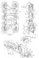
- this support frame 10 comprises, at the like a ladder, two uprights 11 and at least one cross member 12.
- crosspieces 12 are provided in the form of shown embodiment, and they are established at a regular step.
- the uprights 11, which are generally rectilinear, are parallel to each other, and the crosspieces 12, which are themselves generally rectilinear, are perpendicular to them.
- the two uprights 11 used are identical, one to each other, and they act symmetrically with each other, by simple 180 ° reversal in their plan.
- the uprights 11 each have distance from each other, at least two cross-member fixing zones Z, by each of which they are adapted to receive a cross member 12.
- At least one of these areas for fixing the crosspiece Z comprises, aligned with each other in a transverse to the direction extension of the uprights 11, two holes 18, and these intervene at top of a stud 19 which projects from the front face 20 of these uprights 11.
- the uprights 11 also each comprise at least one attachment zone Y 1 , Y 2 suitable for their own attachment to any support, not shown.
- two fixing zones Y 1 , Y 2 are provided in the vicinity of each of the ends 16.
- the attachment zone Y 1 occurs at full surface, while the attachment zone Y 2 is in the form of an ear which projects inwards on the internal longitudinal edge 14.
- each of these fixing zones Y 1 , Y 2 has a hole in the form of a buttonhole, or a keyhole.
- each of the uprights 11 further comprises, locally, independently of Z crossbar attachment zones, and remotely of these, at least one fixing means capable of enabling it to receive, frontally, by simple engagement, and without any other accessory, according to modalities described in more detail later, any other equipment.
- each of the uprights 11 has, recessed, on its edge, at at least one of its ends 16, on its corresponding transverse edge 15, as fixing means M 1 , and to receive any equipment, at least one dovetail notch 21.
- each of the uprights 11 has, at each of its ends 16, on the corresponding transverse edge 15, at least one tail notch dovetail 21.
- tail notch dovetail 21 is provided on such a transverse edge 15.
- each of the uprights 11 has, recessed, on its edge, on its outer longitudinal edge 13, as fixing means M 1 , and to receive any equipment, at least one notch in dovetail 21 of the same type as the previous one.
- the dovetail notch 21 than an upright 11 thus presents on its outer longitudinal edge 13 extends close to one of its ends 16.
- each of the uprights 11 comprises a dovetail notch 21 on its longitudinal edge 13 outside proximity of each of its ends 16.
- each of the uprights 11 also includes, at a distance from its edge, on a socket boss 26 which projects on its front face 20, as fixing means M 2 , and to receive a any equipment, at least one element 28, which is generally dovetailed, and which, for convenience, will therefore be called here dovetail element 28.
- the socket boss 26 is attached to a pillar 29, and each of the uprights 11 has such a boss socket 26 thus leaning against a pillar 29 in the vicinity of each of its ends 16.
- the pillar 29 does not fall under the present invention, it will not be described here.
- each of the socket bosses 26 has, parallel to each other, several dovetail elements 28.
- these dovetail elements 28 are three in number.
- each of the tail elements dovetail 28 which thus has a socket boss 26 is a notch, which, from the front face 30 of this socket boss 26, extends recessed on a lateral face 31 thereof, over at least part of the height of this socket boss 26.
- the relevant side face 31 of the socket bosses 26 is their face opposite to that by which they are attached to a pillar 29, and it is, in practice, a longitudinal face which, parallel to the longitudinal edges 13, 14 of the uprights 11, faces the longitudinal edge 14 inside thereof.
- the tail elements dovetail 28 extend only over part of the height of the bosses socket 26, and the notches which form them each have in plan a curvilinear outline, with a flat bottom 32 and concave lateral sides 33.
- each of the uprights 11 has, locally, projecting from its front face 20, as fixing means M 3 , and to receive any equipment, at least one latching rail 35 having , at a distance from each other, parallel to this front face 20, two square returns 36.
- each of the uprights 11 has a snap rail 35 between the two cross-member fixing zones Z of such a pair.
- Each of the uprights 11 therefore comprises, in the embodiment shown, three snap rails 35, which alternate with the areas of crosspiece fixing Z, and which, along such an upright 11, are generally aligned with each other.
- the snap rails 35 extend parallel to the longitudinal edges 13, 14 of the uprights 11, and, for each of them, the square returns 36 extend back to back.
- these square returns 36 are of unequal length, the one closest to the longitudinal edge 13 outside of the uprights 11 being of length much greater than that of the other.
- a twinning spacer 38 having, projecting, at a distance from each other, at least two bosses in dovetail 39 of contour complementary to that of his or her own dovetail notches 21.
- this spacer twinning 38 generally has a T configuration, with a leg 40 and a cross member 41.
- the leg 40 has, projecting, back to back, away from the crosspiece 41, and, for example, at its free end, as shown, two bosses dovetailed 39.
- the cross member 41 has, on each of its arms 42, in protrusion on the face of such an arm 42 facing the jamb 40, at a distance from this leg 40, and, for example, at the free end of this arm 42, such as shown, a dovetail boss 39.
- leg 40 and the crosspiece 41 are both in the form of flat contour bars both having the same width, and each of the bosses in dovetail 39 is formed by two wings 43, which, arranged in a dihedral, diverge from each other, being internally connected to each other the other by a triangular stiffening rib 44 in their central region.
- the spacer of twinning 38 has, at the free end of its leg 40, a structure in box 45, of rectangular cross section, and it is from this one that back to back extend the corresponding dovetail bosses 39.
- such twinning spacer 38 allows, on request, to couple an upright 11, either with another upright 11 placed side by side, FIG. 7, for a twinning horizontal of two support frames 10, or with another upright 11 arranged end to end, Figure 8, for a vertical twinning of these two chassis support 10.
- the installation of the twinning spacer 38 is advantageously done head-on, by simple engagement of its dovetail bosses 39 in the dovetail notches 21 that show the uprights 11 to be coupled.
- the twinning spacer 38 is in taken with each of the uprights 11 by two dovetail bosses 39, one from its leg 40, the other from its cross member 41.
- the guaranteed pairing is therefore particularly firm and secure.
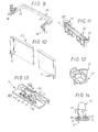
- a equipment 48 in the form of a handle, which, in a manner known per se, is intended for extend from one of the uprights 11 to the other, to form a passage bridge for cables, and each of the legs 49 is equipped, according to the invention, with a twinning spacer 38 of the type described above.
- this twinning spacer 38 intervenes at the free end of such a leg 49, transversely relative to the latter.
- the two twinning spacers 38 of which is thus equipped with the equipment 48 are integral with it, the assembly forming, by molding, a single piece.
- FIGS. 10 to 12 it is associated, more generally, with one at less uprights 11, any equipment 50, 50 'comprising, in projection, at least one dovetail boss 51, 51 ′ capable of cooperating in engagement with any of its dovetail notches 21.
- these pieces of equipment 50, 50 ′ are intended to extend from one to the other of the uprights 11, like the equipment 48 previous.
- the equipment 50 is an openwork plate and the contour of each of the two dovetail bosses 51 that this equipment 50 is generally complementary to that of the notches in dovetail 21 of the uprights 11, in the manner of the tail bosses dovetail 39 of the twinning spacer 38.
- FIGS. 11 and 12 in the equipment 50 ′, here a strip of tube fixing, the contours of the two dovetail bosses 51 'are each respectively complementary for half that of the notches in dovetail 21 of the uprights 11, being further complementary one the other.
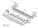
- FIG. 15 it is mounted, following a first equipment 50 "associated with uprights 11, at least one other equipment 50 associated with the same amounts.
- the 51 "dovetail bosses equipment 50” are mounted in the notches 21 of the transverse edges 15, then the dovetail bosses 51 of the equipment 50 are mounted at the continued on the 51 "dovetail bosses in these same notches.
- dovetail bosses 51 of the second equipment 50 therefore cooperate with the same notches 21 as those where the tail bosses are already fitted dovetail 51 "of the first equipment 50".
- the 50 "equipment is sandwiched between the uprights and the equipment 50.
- the bosses 51 of the equipment 50 are formed at the end of spacer rods 50B of length at least equal to the thickness of equipment 50 "and find support by form complementarity on this latest.
- tubes can be introduced through the equipment 50 through openings 50A knockouts and held in place by 50 "equipment claws as soon as introduction in the box.
- At least one of the uprights 11 At least one item of equipment 52 comprising, on its underside 53, latching means 54, in this case in the form of hooks, by which it is able to be attached, by snap-fastening, to one or other of the latching rails 35 that such an upright includes 11.
- this equipment 52 is a terminal block.
- such a terminal block comprises, in in addition, on one of its lateral faces 56, at least one tail element dovetail 57, the cross section of which is complementary to that of dovetail elements 28 which have the interlocking bosses 26 of the uprights 11, and by which it is thus able to engage with one any of these socket bosses 26, by simple engagement frontal.
- the equipment 52 has, parallel to each other, two dovetail elements 57, and these are columns which protrude from its side face 56 concerned.
- these columns are hollow and their cross section is open.
- Such equipment 52 thus arranged can therefore be installed either on the snap rails 35, or on a socket boss 26.
Landscapes
- Engineering & Computer Science (AREA)
- Power Engineering (AREA)
- Assembled Shelves (AREA)
- Mutual Connection Of Rods And Tubes (AREA)
- Mounting Components In General For Electric Apparatus (AREA)
Description
Claims (24)
- Montant pour châssis de support, notamment pour appareillage électrique, du genre comportant, à distance l'une de l'autre, au moins deux zones de fixation de traverse (Z) par chacune desquelles il est adapté à recevoir une traverse (12), comportant indépendamment des zones de fixation de traverse (Z), et à distance de celle-ci, au moins un moyen de fixation du genre queue d'aronde apte à lui permettre de recevoir, frontalement, un quelconque autre équipement, caractérisé en ce qu'il comporte, débouchant en creux sur sa tranche, à l'une au moins de ses extrémités (16), au moins une encoche en queue d'aronde (21).
- Montant suivant la revendication 1, caractérisé en ce qu'il comporte, à chacune de ses extrémités (16), sur le bord transversal (15) correspondant, au moins une encoche en queue d'aronde (21).
- Montant suivant l'une quelconque des revendications 1 à 2, caractérisé en ce que, pour recevoir un quelconque équipement, il comporte, en creux sur sa tranche, sur son bord longitudinal (13) extérieur, au moins une encoche en queue d'aronde (21).
- Montant suivant la revendication 3, caractérisé en ce que l'encoche en queue d'aronde (21) qu'il présente sur son bord longitudinal (13) extérieur s'étend à proximité de l'une de ses extrémités (16).
- Montant suivant la revendication 4, caractérisé en ce qu'il comporte une encoche en queue d'aronde (21) sur son bord longitudinal (13) extérieur à proximité de chacune de ses extrémités (16).
- Montant suivant l'une quelconque des revendications 2 à 5, caractérisé en ce que la ou les encoches en queue d'aronde (21) qu'il présente sur un bord (13, 15) s'étendent sur toute son épaisseur.
- Montant suivant l'une quelconque des revendications 2 à 6, caractérisé en qu'il lui est associé, à titre d'équipement, une entretoise de jumelage (38) présentant, en saillie, à distance l'un de l'autre, au moins deux bossages en queue d'aronde (39) de contour complémentaire de celui de sa ou de ses propres encoches en queue d'aronde (21).
- Montant suivant la revendication 7, caractérisé en ce que l'entretoise de jumelage (38) qui lui est associée a globalement une configuration en T, avec un jambage (40) et une traverse (41), le jambage (40) présentant, en saillie, dos à dos, à distance de la traverse (41), deux bossages en queue d'aronde (39), et la traverse (41) présentant, sur chacun de ses bras (42), en saillie sur la face d'un tel bras (42) tournée vers le jambage (40), à distance de ce jambage (40), un bossage en queue d'aronde (39).
- Montant suivant l'une quelconque des revendications 7, 8, caractérisé en ce qu'il lui est associé un équipement (48) dont est solidaire au moins une entretoise de jumelage (38).
- Montant suivant la revendication 9, caractérisé en ce qu'il lui est associé un équipement (48), en forme d'anse, dont chacun des jambages (49) est équipé d'une entretoise de jumelage (38).
- Montant suivant l'une quelconque des revendications 2 à 6, caractérisé en ce qu'il lui est associé un équipement (50, 50', 50") qui comporte, en saillie, au moins un bossage queue d'aronde (51, 51', 51'') propre à coopérer en engagement avec l'une quelconque de ses encoches en queue d'aronde (21).
- Montant suivant la revendication 11, caractérisé en ce qu'il lui est associé un équipement (50, 50', 50") comportant, en saillie, à distance l'un de l'autre, deux bossages queue d'atronde (51, 51', 51'').
- Montant suivant la revendication 12, caractérisé en ce qu'il lui est associé un équipement (50') dont les bossages queue d'aronde (51') ont des contours qui, complémentaires l'un de l'autre, sont chacun respectivement complémentaires pour moitié de celui d'une encoche en queue d'aronde (21).
- Montant suivant l'une quelconque des revendications 11 à 13, caractérisé en ce que plusieurs équipements sont associés à une même encoche en queue d'aronde (21) avec des bossages queue d'aronde respectifs adaptés à être introduits successivement dans la même encoche (21).
- Montant suivant la revendication 14, caractérisé en ce que plusieurs équipements (50, 50") sont associés à au moins un jeu d'au moins deux encoches en queue d'aronde (21) avec des jeux correspondants de bossages queue d'aronde (51, 51") respectivement adaptés aux dites encoches (21).
- Montant suivant la revendication 1, caractérisé en ce que, pour recevoir un quelconque équipement, il comporte, à distance de sa tranche, sur un bossage d'emboítement (26) qui fait saillie sur sa face avant (20), au moins un élément de queue d'aronde (28).
- Montant suivant la revendication 16, caractérisé en ce que l'élément de queue d'aronde (28) qu'il présente sur son bossage d'emboítement (26) est une encoche, qui, à compter de la face avant (30) de ce bossage d'emboítement (26), s'étend en creux sur une face latérale (31) de celui-ci, sur une partie au moins de la hauteur de ce bossage d'emboítement (26).
- Montant suivant l'une quelconque des revendications 16, 17, caractérisé en ce que le bossage d'emboítement (26) qu'il comporte présente, parallèlement les uns aux autres, plusieurs éléments de queue d'aronde (28).
- Montant suivant l'une quelconque des revendications 16 à 18, caractérisé en ce qu'il comporte un bossage d'emboítement (26) au voisinage de chacune de ses extrémités (16).
- Montant suivant la revendication 1, caractérisé en ce que, pour recevoir un quelconque équipement, il comporte, en outre, localement, en saillie sur sa face avant (20), au moins un rail d'encliquetage (35) présentant, parallèlement à cette face avant (20), deux retours en équerre (36).
- Montant suivant la revendication 20, caractérisé en ce que les retours en équerre (36) du rail d'encliquetage (35) s'étendent dos à dos.
- Montant suivant l'une quelconque des revendications 20, 21, caractérisé en ce que le rail d'encliquetage (35) s'étend parallèlement à ses bords longitudinaux (13, 14).
- Montant suivant l'une quelconque des revendications 20 à 22, caractérisé en ce que, pour chaque paire de zones de fixation de traverse (Z) successives, il comporte un rail d'encliquetage (35) entre les deux zones de fixation de traverse (Z) d'une telle paire.
- Châssis de support, notamment pour appareillage électrique, caractérisé en ce qu'il comprend au moins deux montants selon l'une quelconque des revendications précédentes.
Applications Claiming Priority (2)
| Application Number | Priority Date | Filing Date | Title |
|---|---|---|---|
| FR9714155A FR2770961B1 (fr) | 1997-11-12 | 1997-11-12 | Montant pour chassis de support, notamment pour appareillage electrique |
| FR9714155 | 1997-11-12 |
Publications (2)
| Publication Number | Publication Date |
|---|---|
| EP0917268A1 EP0917268A1 (fr) | 1999-05-19 |
| EP0917268B1 true EP0917268B1 (fr) | 2001-08-16 |
Family
ID=9513263
Family Applications (1)
| Application Number | Title | Priority Date | Filing Date |
|---|---|---|---|
| EP19980402785 Expired - Lifetime EP0917268B1 (fr) | 1997-11-12 | 1998-11-10 | Montant pour châssis de support, notamment pour appareillage électrique |
Country Status (4)
| Country | Link |
|---|---|
| EP (1) | EP0917268B1 (fr) |
| DE (1) | DE69801357T2 (fr) |
| ES (1) | ES2159423T3 (fr) |
| FR (1) | FR2770961B1 (fr) |
Families Citing this family (3)
| Publication number | Priority date | Publication date | Assignee | Title |
|---|---|---|---|---|
| FR2886067B1 (fr) * | 2005-05-19 | 2012-09-28 | Legrand France | Coffret modulable pour appareillages electriques |
| NL2001222C2 (nl) * | 2008-01-28 | 2009-07-30 | Abb Bv | Installatiekast voor een rij elektrisch schakelmateriaal. |
| EP2338802B1 (fr) | 2009-12-23 | 2015-09-02 | The Procter and Gamble Company | Lot temporaire de boîtes de petite largeur |
Family Cites Families (4)
| Publication number | Priority date | Publication date | Assignee | Title |
|---|---|---|---|---|
| DE2944372C2 (de) * | 1979-11-02 | 1982-08-26 | Agalitwerk Milspe Kattwinkel GmbH & Co, 5820 Gevelsberg | Traggerüst für elektrische Geräte |
| DE9416322U1 (de) * | 1994-09-29 | 1994-11-24 | Siemens AG, 80333 München | Verbindungseinheit einer Aufnahme- und Befestigungseinrichtung für Profilschienen |
| DE19521001A1 (de) * | 1995-06-08 | 1996-12-19 | Siemens Ag | Kommunikationsfähige Schaltgeräteeinheit |
| FR2738104B1 (fr) * | 1995-08-25 | 1997-10-31 | Legrand Sa | Chassis de support, notamment pour appareillages electriques |
-
1997
- 1997-11-12 FR FR9714155A patent/FR2770961B1/fr not_active Expired - Fee Related
-
1998
- 1998-11-10 EP EP19980402785 patent/EP0917268B1/fr not_active Expired - Lifetime
- 1998-11-10 ES ES98402785T patent/ES2159423T3/es not_active Expired - Lifetime
- 1998-11-10 DE DE1998601357 patent/DE69801357T2/de not_active Expired - Fee Related
Also Published As
| Publication number | Publication date |
|---|---|
| EP0917268A1 (fr) | 1999-05-19 |
| FR2770961B1 (fr) | 2000-01-28 |
| FR2770961A1 (fr) | 1999-05-14 |
| DE69801357T2 (de) | 2002-06-13 |
| DE69801357D1 (de) | 2001-09-20 |
| ES2159423T3 (es) | 2001-10-01 |
Similar Documents
| Publication | Publication Date | Title |
|---|---|---|
| EP0241344B1 (fr) | Dispositif d'assemblage d'ossature de stand pour exposition temporaire | |
| EP0725464B1 (fr) | Socle pour armoire électrique ou analogue et armoire équipée d'un tel socle | |
| EP1127394B1 (fr) | Dispositif de fixation d'un fil sur un element porteur muni d'au moins une ouverture et ensemble porteur pour chemin de cables comportant au moins un tel dispositif | |
| WO2001003266A1 (fr) | Accessoire de fixation pour chemin de cables en fils, et chemin de cables en fils equipe au moins d'un tel accessoire | |
| FR2697274A1 (fr) | Revêtement de mur avec système de support. | |
| CA2820783A1 (fr) | Dispositif et ensemble de maintien d'une paire de balais d'essuie-glaces, emballage et procede de montage correspondants | |
| EP0760546B1 (fr) | Châssis de support, notamment pour appareillages électriques | |
| FR2579262A1 (fr) | Dispositif d'antidecrochage pour porte coulissante | |
| EP1071183B1 (fr) | Support d'appareillage électrique à rapporter sur une goulotte | |
| EP1149447B1 (fr) | Support d'appareillage, notamment pour appareillage electrique, et boitier comportant un tel support d'appareillage | |
| EP0762585B1 (fr) | Accessoire de support pour l'assujettissement d'un barreau à un autre élément de châssis,notamment pour le support d'appareils électriques | |
| EP0917268A1 (fr) | Montant pour châssis de support, notamment pour appareillage électrique | |
| EP0762586B1 (fr) | Coffret, notamment pour appareils électriques | |
| EP0989647B1 (fr) | Châssis, notamment pour appareillage électrique | |
| FR2681403A1 (fr) | Dispositif d'assemblage pour profiles d'ossature, ossature correspondante, et armoire, en particulier armoire pour appareillages electriques, mettant en óoeuvre une telle ossature. | |
| FR2999024A1 (fr) | Appareillage electrique et rehausse pour un tel appareillage electrique | |
| FR2519243A1 (fr) | Rayonnage | |
| FR2664633A1 (fr) | Plafond suspendu. | |
| EP0725467A1 (fr) | Dispositif de fixation pour l'assemblage des chemins de câbles en tÔle d'acier | |
| FR2698516A1 (fr) | Dispositif de jumelage pour embase, notamment pour coffret électrique. | |
| BE1011960A3 (fr) | Boitier multiposte pour le montage aligne d'au moins deux appareillages electriques. | |
| FR2536128A1 (fr) | Agrafe elastique pour fixer un panneau sur un support | |
| EP1022833A1 (fr) | Adaptateur pour support de mécanisme, et support de mécanisme équipé d'au moins un tel adaptateur, notamment pour appareillage électrique | |
| EP0779641A1 (fr) | Module d'espacement, notamment pour appareil électrique modulaire | |
| EP3456904B1 (fr) | Coffre pour véhicule à deux roues |
Legal Events
| Date | Code | Title | Description |
|---|---|---|---|
| PUAI | Public reference made under article 153(3) epc to a published international application that has entered the european phase |
Free format text: ORIGINAL CODE: 0009012 |
|
| AK | Designated contracting states |
Kind code of ref document: A1 Designated state(s): BE DE ES FR GB IT |
|
| AX | Request for extension of the european patent |
Free format text: AL;LT;LV;MK;RO;SI |
|
| 17P | Request for examination filed |
Effective date: 19990611 |
|
| AKX | Designation fees paid |
Free format text: BE DE ES FR GB IT |
|
| GRAG | Despatch of communication of intention to grant |
Free format text: ORIGINAL CODE: EPIDOS AGRA |
|
| 17Q | First examination report despatched |
Effective date: 20001207 |
|
| GRAG | Despatch of communication of intention to grant |
Free format text: ORIGINAL CODE: EPIDOS AGRA |
|
| GRAH | Despatch of communication of intention to grant a patent |
Free format text: ORIGINAL CODE: EPIDOS IGRA |
|
| GRAH | Despatch of communication of intention to grant a patent |
Free format text: ORIGINAL CODE: EPIDOS IGRA |
|
| GRAA | (expected) grant |
Free format text: ORIGINAL CODE: 0009210 |
|
| AK | Designated contracting states |
Kind code of ref document: B1 Designated state(s): BE DE ES FR GB IT |
|
| REF | Corresponds to: |
Ref document number: 69801357 Country of ref document: DE Date of ref document: 20010920 |
|
| REG | Reference to a national code |
Ref country code: ES Ref legal event code: FG2A Ref document number: 2159423 Country of ref document: ES Kind code of ref document: T3 |
|
| GBT | Gb: translation of ep patent filed (gb section 77(6)(a)/1977) |
Effective date: 20011003 |
|
| REG | Reference to a national code |
Ref country code: GB Ref legal event code: IF02 |
|
| PLBE | No opposition filed within time limit |
Free format text: ORIGINAL CODE: 0009261 |
|
| STAA | Information on the status of an ep patent application or granted ep patent |
Free format text: STATUS: NO OPPOSITION FILED WITHIN TIME LIMIT |
|
| 26N | No opposition filed | ||
| PGFP | Annual fee paid to national office [announced via postgrant information from national office to epo] |
Ref country code: BE Payment date: 20061128 Year of fee payment: 9 |
|
| BERE | Be: lapsed |
Owner name: *LEGRAND SNC Effective date: 20071130 Owner name: *LEGRAND Effective date: 20071130 |
|
| PG25 | Lapsed in a contracting state [announced via postgrant information from national office to epo] |
Ref country code: BE Free format text: LAPSE BECAUSE OF NON-PAYMENT OF DUE FEES Effective date: 20071130 |
|
| PGFP | Annual fee paid to national office [announced via postgrant information from national office to epo] |
Ref country code: DE Payment date: 20081113 Year of fee payment: 11 |
|
| PGFP | Annual fee paid to national office [announced via postgrant information from national office to epo] |
Ref country code: ES Payment date: 20081120 Year of fee payment: 11 |
|
| PGFP | Annual fee paid to national office [announced via postgrant information from national office to epo] |
Ref country code: IT Payment date: 20081114 Year of fee payment: 11 |
|
| PGFP | Annual fee paid to national office [announced via postgrant information from national office to epo] |
Ref country code: GB Payment date: 20081107 Year of fee payment: 11 |
|
| GBPC | Gb: european patent ceased through non-payment of renewal fee |
Effective date: 20091110 |
|
| PG25 | Lapsed in a contracting state [announced via postgrant information from national office to epo] |
Ref country code: DE Free format text: LAPSE BECAUSE OF NON-PAYMENT OF DUE FEES Effective date: 20100601 |
|
| PG25 | Lapsed in a contracting state [announced via postgrant information from national office to epo] |
Ref country code: GB Free format text: LAPSE BECAUSE OF NON-PAYMENT OF DUE FEES Effective date: 20091110 |
|
| REG | Reference to a national code |
Ref country code: ES Ref legal event code: FD2A Effective date: 20110324 |
|
| PG25 | Lapsed in a contracting state [announced via postgrant information from national office to epo] |
Ref country code: IT Free format text: LAPSE BECAUSE OF NON-PAYMENT OF DUE FEES Effective date: 20091110 |
|
| PG25 | Lapsed in a contracting state [announced via postgrant information from national office to epo] |
Ref country code: ES Free format text: LAPSE BECAUSE OF NON-PAYMENT OF DUE FEES Effective date: 20110310 |
|
| PG25 | Lapsed in a contracting state [announced via postgrant information from national office to epo] |
Ref country code: ES Free format text: LAPSE BECAUSE OF NON-PAYMENT OF DUE FEES Effective date: 20091111 |
|
| PGFP | Annual fee paid to national office [announced via postgrant information from national office to epo] |
Ref country code: FR Payment date: 20141128 Year of fee payment: 17 |
|
| REG | Reference to a national code |
Ref country code: FR Ref legal event code: ST Effective date: 20160729 |
|
| PG25 | Lapsed in a contracting state [announced via postgrant information from national office to epo] |
Ref country code: FR Free format text: LAPSE BECAUSE OF NON-PAYMENT OF DUE FEES Effective date: 20151130 |