EP0916893A2 - Leuchte mit besonders vielseitigen Ausstattungsmöglichkeiten - Google Patents
Leuchte mit besonders vielseitigen Ausstattungsmöglichkeiten Download PDFInfo
- Publication number
- EP0916893A2 EP0916893A2 EP98121046A EP98121046A EP0916893A2 EP 0916893 A2 EP0916893 A2 EP 0916893A2 EP 98121046 A EP98121046 A EP 98121046A EP 98121046 A EP98121046 A EP 98121046A EP 0916893 A2 EP0916893 A2 EP 0916893A2
- Authority
- EP
- European Patent Office
- Prior art keywords
- lamp
- mains
- phase
- additional
- luminaire
- Prior art date
- Legal status (The legal status is an assumption and is not a legal conclusion. Google has not performed a legal analysis and makes no representation as to the accuracy of the status listed.)
- Withdrawn
Links
- 238000009420 retrofitting Methods 0.000 claims abstract description 9
- 238000003475 lamination Methods 0.000 claims abstract description 6
- 230000001681 protective effect Effects 0.000 claims abstract description 6
- 230000033001 locomotion Effects 0.000 claims description 11
- 239000004020 conductor Substances 0.000 claims description 3
- 230000007935 neutral effect Effects 0.000 claims description 3
- 239000000779 smoke Substances 0.000 claims description 3
- 230000003449 preventive effect Effects 0.000 claims description 2
- 238000000926 separation method Methods 0.000 claims description 2
- 230000000007 visual effect Effects 0.000 claims description 2
- 230000008878 coupling Effects 0.000 claims 1
- 238000010168 coupling process Methods 0.000 claims 1
- 238000005859 coupling reaction Methods 0.000 claims 1
- 239000004065 semiconductor Substances 0.000 claims 1
- 238000010276 construction Methods 0.000 abstract 1
- 230000008901 benefit Effects 0.000 description 4
- 238000001514 detection method Methods 0.000 description 4
- 238000005516 engineering process Methods 0.000 description 3
- 238000009434 installation Methods 0.000 description 2
- 238000011161 development Methods 0.000 description 1
- 230000018109 developmental process Effects 0.000 description 1
- 238000005286 illumination Methods 0.000 description 1
- 238000000034 method Methods 0.000 description 1
- 230000003287 optical effect Effects 0.000 description 1
- 125000006850 spacer group Chemical group 0.000 description 1
Images


Classifications
-
- F—MECHANICAL ENGINEERING; LIGHTING; HEATING; WEAPONS; BLASTING
- F21—LIGHTING
- F21V—FUNCTIONAL FEATURES OR DETAILS OF LIGHTING DEVICES OR SYSTEMS THEREOF; STRUCTURAL COMBINATIONS OF LIGHTING DEVICES WITH OTHER ARTICLES, NOT OTHERWISE PROVIDED FOR
- F21V33/00—Structural combinations of lighting devices with other articles, not otherwise provided for
- F21V33/0004—Personal or domestic articles
- F21V33/0052—Audio or video equipment, e.g. televisions, telephones, cameras or computers; Remote control devices therefor
- F21V33/0056—Audio equipment, e.g. music instruments, radios or speakers
-
- F—MECHANICAL ENGINEERING; LIGHTING; HEATING; WEAPONS; BLASTING
- F21—LIGHTING
- F21V—FUNCTIONAL FEATURES OR DETAILS OF LIGHTING DEVICES OR SYSTEMS THEREOF; STRUCTURAL COMBINATIONS OF LIGHTING DEVICES WITH OTHER ARTICLES, NOT OTHERWISE PROVIDED FOR
- F21V29/00—Protecting lighting devices from thermal damage; Cooling or heating arrangements specially adapted for lighting devices or systems
- F21V29/15—Thermal insulation
-
- H—ELECTRICITY
- H01—ELECTRIC ELEMENTS
- H01R—ELECTRICALLY-CONDUCTIVE CONNECTIONS; STRUCTURAL ASSOCIATIONS OF A PLURALITY OF MUTUALLY-INSULATED ELECTRICAL CONNECTING ELEMENTS; COUPLING DEVICES; CURRENT COLLECTORS
- H01R33/00—Coupling devices specially adapted for supporting apparatus and having one part acting as a holder providing support and electrical connection via a counterpart which is structurally associated with the apparatus, e.g. lamp holders; Separate parts thereof
- H01R33/90—Coupling devices specially adapted for supporting apparatus and having one part acting as a holder providing support and electrical connection via a counterpart which is structurally associated with the apparatus, e.g. lamp holders; Separate parts thereof adapted for co-operation with two or more dissimilar counterparts
Definitions
- the invention relates to a lamp with particularly versatile Equipment options, which without version for both different performance levels and the associated different lamp bases as well as for different Retrofitting options without changing the housing shape is suitable.
- the reflectors are shaped and depending on the desired lighting technology fastened with small screws in the luminaire housing.
- this includes Light sensors available on the market at 1-10 volts Control input terminal of the dimmable in the lamp Ballast to connect.
- a combination of the lamp with a motion detector is already taken into account when designing the luminaire housing and thus also set.
- frames are used as purchased parts, they are created under Consideration of the codes, the installation positions, the Attachment options and other criteria a big one Variety of types, which the storage at the luminaire manufacturers difficult.
- the sockets must be mounted separately and be connected. This includes additional assembly times and increased risk of error in itself.
- the disadvantage with the conventional mounting of the reflector in Luminaire housing is that the mounting screws are somewhere are placed in the reflector center and the screw heads through Reflection can disrupt lighting technology. Furthermore, the Reflector a curved outer contour, which depending on the calculation one has a different distance from the housing. Corresponding spacers or molded pins between the housing and reflector can fit and limit only for one reflector calculation multifunctional use.
- the object of the invention is to provide a lamp with special to create versatile equipment options, in which the above disadvantages are eliminated and due to the Design of the lamp housing many more interesting Retrofitting options are available. This task is accomplished by a Luminaire with the features of claim 1 solved, Further developments are described in the subclaims.
- a lamp is known, in which the electronic ballast in the form of a circuit board ring is arranged around the thermal protection wall.
- the following Design features improve functionality and Versatility of this lamp significantly and will now be described.
- the cable entries are all behind the Thermal protection wall. Two more axial walls create the spatial Separation between board space and connection space.
- circuit board ring is in the upper part of the lamp shifted. This brings thermal benefits to the electronics that is thus in the coolest place within the lamp.
- the circuit board ring with its terminals is built in To achieve or even replace the condition of the lamp. This is a very significant advantage in the event of a mistake.
- the thermal protection wall is closed except for a partial area circulating. On top of it are embedded the Reflector retaining screws, which are now the reflector regardless can keep the shape.
- the section of the thermal protection wall has two grooves in which two boards can be inserted instead of the thermal protection film. These two boards also represent a thermal protection wall and close the area between the reflector space and the circuit board space again. In addition, the two boards replace the sockets.
- the front board has openings that exactly coded profiles or the entire section of all possible Codings of the lamp base corresponds.
- the rear board has soldered spring clips, socket contacts for the Lamp connector pins and, if necessary, coding locking pins for the inevitable use of only the correct lamp base.
- the luminaire housing is both in the center for single-lamp assembly also designed for two-flame assembly on the side.
- the rear board is pluggably connected to the board ring.
- the front and rear inserted board can also jump in the deep part of the lamp used to be in the lamp center another pluggable board for a socket for vertical to reach equipped lamps.
- the lamp housing and the circuit board ring can be without Shape change continue to be used.
- the board connector technology is moreover extremely compact and completely free of wiring.
- These include, for example, light control, light control, a motion detector, an operating hours counter, an alarm system, a timer, a remote control, an EIB bus coupler, a smoke detector for preventive fire protection, an overvoltage module for the medium and fine protection, a bio-rhythm control which the The brightness of the lights matches the natural biorythm of humans adapts a POWER-NET coupler and other special circuits.
- the slot for the light control add-on module has two Plug contacts that connect directly to the 1-10 volt control input terminal of the integrated dimmable ballast are connected.
- the Light control add-on module can be plugged in and the Lux value preselection regulate the corresponding luminaire. You can also the control wires of the neighboring lights to the Control input terminal connected and in parallel by only one Additional light control module can also be controlled.
- the slot for all other module variants has two Plug contacts with phase and zero of the mains connection terminal of the integrated ballast are connected.
- the slot for all other module variants has two Plug contacts with phase and zero of the mains connection terminal of the integrated ballast are connected.
- the Additional module there are four different basic electrical circuits to select.
- the additional module is connected via the two Plug contacts connected to phase and zero of the lamp.
- the first three terminals form the unprotected one Mains input with phase, zero and earth. Form clamps four and five the protected mains output of the overvoltage module. From there from the further wiring into the luminaire in question and also in other neighboring lights.
- the additional module is connected via the two Plug contacts connected to phase and zero of the lamp.
- these additional modules have their own Mains phase connector.
- the neutral conductor When retrofitting the additional module the neutral conductor to the neutral conductor terminal of the lamp connected.
- the phase is in the Mains phase connection terminal of the additional module connected.
- Switching events such as those with motion detectors, Timers, remote controls, light control devices, biorythm controls or bus couplers occur, switch the continuous phase via a relay to the phase contact of the lamp. With this procedure a There is no jumper in the luminaire if no additional module is populated.
- the mains phase connector of the Luminaire for a switching phase output which via another Jumper wire can operate adjacent lights in parallel.
- additional modules such as Motion detectors can be supplied in parallel.
- Each lamp with one own motion detector add-on module would cover the detection area multiply and upon detection all lights in this group turn on.
- the third basic circuit is also used with additional modules such as for example alarm systems or smoke detectors.
- additional modules such as for example alarm systems or smoke detectors.
- the mains phase connection terminal on the additional module serves as Continuous phase input.
- the light or switching phase is on the Mains phase connection of the lamp connected. So is the additional module also supplied with mains voltage when the lamp is switched off.
- the additional module can connect the lamp with a bridge switch on, for example when a fire breaks out.
- the fourth basic circuit is used, for example, with EIB bus couplers, POWER NET couplers or lighting controls.
- the fourth Basic circuit is identical to the third basic circuit except for the extension that the additional modules via a 1-10 volt control output terminal feature. This is done by means of two Wire jumpers with the control input terminal of the integrated dimmable electronic ballast connected.
- Fig.1 shows the lamp from the top view.
- the circuit board ring 1 is arranged around the thermal protection wall 2.
- the cable entries 3 are located outside the thermal protection wall 2.
- Two axial walls 4 separate the area between the connection space 6 and the circuit board space 5.
- the power supply terminal 7 is attached to the left side and the control input terminal 8 to the right side.
- the mains filter 9 and the harmonic filter 10 are spatially well separated from the high-frequency range 11.
- the limit switches 12 behind the protective wall 13 switch off all poles of the mains voltage when the luminaire housing 20 is opened by removing the ceiling ring or the lamination.
- the thermal protection wall 2 is closed all the way down to the partial area 14.
- the reflector retaining screws 15 are arranged on it.
- the section 14 has two grooves 16 into which two boards 18, 19 are inserted.
- the two boards 18, 19 also form a thermal protection wall and close the area between the reflector space 17 and the board space 5.
- the front board 18 has openings which correspond exactly to the coding of the lamp base.
- the rear circuit board 19 has soldered holding clips, socket contacts for the lamp connecting pins and, if appropriate, coding pins which prevent the wrong lamp socket from being inserted.
- the slots 21 are reserved for the additional modules.
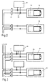
- FIG. 2 shows a basic circuit for the additional light control module 22. This is connected to the control input terminal 8 via the plug contacts 23.
- the additional module 22 thus regulates the lamp 25 and, if desired, further neighboring lamps 26.
- FIG 3 shows the first basic circuit for the additional module 28. This is connected to the power supply terminal 7 via the plug contacts 27.
- the additional module 28 receives mains voltage depending on the lamp 25. This circuit is suitable for example for operating hours counters.
- the additional module 29 has a five-pole connection terminal 30.
- the first three terminals form the unprotected mains input of the overvoltage module 29 with phase, zero and earth.
- Terminals four and five form the protected mains output of the overvoltage module 29. This output can be connected to the mains connection terminal 7 of the relevant lamp 25 or other neighboring lights 26 can be connected.
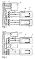
- FIG. 5 shows the third basic circuit for the additional module 32-37.
- This is connected to the mains connection terminal 7 of the lamp 25 via the plug contacts 27.
- the additional module 32-37 has its own mains phase connection terminal 31, via which it draws mains voltage. Switching commands of the additional module 32-37 conduct the mains voltage via an internal relay to the mains phase connection of the lamp 25.
- the mains phase connection of the lamp 25 becomes a switching phase output and can supply 39 additional neighboring lamps 26 with an additional switching wire. If an additional module 32-37, as shown in dashed lines 40, is connected in the neighboring lamp 26, the additional modules are operated in parallel. Each lamp can thus switch on all other neighboring lamps. This is a very important advantage when using motion detector add-on modules, for example, because the detection areas of several motion detectors overlap and add, and the reliability in operation is increased as a result.
- FIG. 6 shows the third basic circuit for an additional module 41-42 with permanent network connection.
- the additional module 41- 42 is connected to the mains connection terminal 7 of the lamp 25 via the plug contacts 27 and receives a continuous phase 44 via its own mains phase connection terminal 31.
- the phase connection of the lamp 25 receives the light or switching phase 43 of the installation.
- the additional module 41-42 is always supplied with mains voltage, even if the light or switching phase 43 is switched off.
- the lamp 25 can optionally be switched on by the additional module 41-42.
- FIG. 7 shows the fourth basic circuit for an additional module 46-48.
- the fourth basic circuit is identical to the third basic circuit. Only the additional module 46-48 has a control output terminal 49. This is connected to the control input terminal 8 of the electronic ballast 24 of the lamp 25 by means of two wire jumpers 50.
- This basic circuit is used for bus couplers or lighting controls that can execute switching and dimming commands.
Landscapes
- Engineering & Computer Science (AREA)
- Multimedia (AREA)
- General Engineering & Computer Science (AREA)
- Circuit Arrangement For Electric Light Sources In General (AREA)
- Arrangement Of Elements, Cooling, Sealing, Or The Like Of Lighting Devices (AREA)
Abstract
Es ist die Aufgabe der Erfindung, eine Leuchte anzugeben, die aufgrund ihrer Konstruktion ohne eine Zukauffassung auskommt, multifunktional einzusetzen ist und für verschiedene Nachrüstmöglichkeiten per steckbarer Zusatzmodule geeignet ist.
Description
- Fig. 1:
- Leuchte aus der Draufsicht
- Fig. 2:
- Grundschaltung für Lichtregelzusatzmodul
- Fig. 3:
- Erste Grundschaltung für Zusatzmodule
- Fig. 4:
- Zweite Grundschaltung für Zusatzmodule
- Fig. 5:
- Dritte Grundschaltung für Zusatzmodule
- Fig. 6:
- Dritte Grundschaltung für Zusatzmodule mit Dauernetzanschluß
- Fig. 7:
- Vierte Grundschaltung für Zusatzmodule
Claims (5)
- Leuchte mit besonders vielseitigen Ausstattungsmöglichkeiten, ohne Fassung geeignet zur Aufnahme von Lampen mit verschiedenen Leistungsstufen und verschiedenen Lampensockeln und ohne Änderung der Gehäuseform geeignet für verschiedene Nachrüstmöglichkeiten
wobei
die Kabeleinführungen (3) sich hinter der Thermoschutzwand (2) befinden, wobei zwei weitere axiale Wände (4) die räumliche Trennung zwischen Platinenraum (5) und Anschlußraum (6) erzeugen, wobei hinter den axialen Wänden (4) in der einen Richtung die Netzanschlußklemme (7) und in der anderen Richtung die Steuereingangsklemme (8) angeordnet ist, wobei der Platinenring (1) in den oberen Teil der Leuchte verlagert ist, wobei die Sicherheit vor Berührung von spannungsführenden Teilen durch die Endschalter (12) gewährleistet ist und sich die Endschalter (12) hinter der Schutzwand (13) befinden und beim Entfernen der Abdeckung die Netzspannung allpolig abschalten, wobei die Thermoschutzwand (2) bis auf einen Teilbereich (14) geschlossen und umlaufend ist, wobei sich an der Thermoschutzwand (2) , auf der Oberseite eingelassen, die Reflektorhalteschrauben (15) befinden, wobei der Teilbereich (14) der Thermoschutzwand (2) zwei Nuten (16) besitzt und in die Nuten zwei Platinen (18, 19) eingeschoben werden, wobei die zwei Platinen (18, 19) ebenfalls eine Thermoschutzwand darstellen und den Bereich zwischen Reflektorraum (17) und Platinenraum (5) schließen, wobei die zwei Platinen (18, 19) die Fassung ersetzen, wobei die vordere Platine (18) Durchbrüche besitzt und diese genau den codierten Profilen oder dem Gesamtausschnitt aller möglichen Codierungen der Lampensockel entspricht, wobei die hintere Platine (19) angelötete Halteklammern und Steckbuchsenkontakte für die Lampenanschlußstifte und gegebenenfalls Codiersperrstifte für den zwangsläufigen Einsatz nur des richtigen Lampensockels besitzt, wobei das Leuchtengehäuse sowohl für eine einflammige Lampenbestückung mittig als auch für eine zweiflammige Lampenbestückung seitlich ausgelegt ist, wobei die hintere Platine (19) steckbar mit dem Platinenring (1) verbunden ist, wobei die zwei Platinen (18, 19) zum Versprung in den tiefen Teil der Leuchte benutzt werden können und die zwei Platinen (18, 19) im Leuchtenzentrum eine weitere steckbare Platine für vertikal bestückte Lampen erreichen, wobei Teilbereiche des Platinenrings (1) reserviert und mit Steckkontakten (23, 27) versehen sind, wobei auf die reservierten Steckplätze (21) Zusatzmodule eingesteckt werden können, wobei die Kaschierung oder der Abdeckring Fenster oder Durchbrüche für die Sichtverbindung der Zusatzmodule zum Raum enthalten kann, wobei das Zusatzmodul beispielsweise eine Lichtregelung (22) oder eine Lichtsteuerung (35) oder einen Bewegungsmelder (32) oder einen Betriebsstundenzähler (28) oder eine Alarmanlage (41) oder einen Timer (33) oder eine Infrarotfernsteuerung (34) oder eine Funkfernsteuerung (34) oder eine Ultraschallfernsteuerung (34) oder einen EIB-Busankoppler (46) oder einen Rauch- und Feuermelder (42) für den vorbeugenden Brandschutz oder ein Überspannungsmodul (29) oder eine Bioryhtmuslichtsteuerung (36) für die Anpassung der Helligkeit dem natürlichen Biorythmus des Menschen oder einen POWER NET- Koppler (47) oder beliebige andere Schaltungen (48) verkörpert, wobei der Steckplatz (21) für das Lichtregelzusatzmodul (22) über zwei Steckkontakte (23) verfügt und die Steckkontakte (23) mit der Steuereingangsklemme (8) des integrierten dimmbaren Vorschaltgerätes (24) verbunden sind, wobei der Steckplatz (21) für alle anderen Zusatzmodulvarianten über zwei Steckkontakte (27) verfügt und die zwei Steckkontakte (27) mit Phase und Null der Netzanschlußklemme (7) verbunden sind, wobei die Zusatzmodule je nach Aufgabe über eigene Anschlußklemmen (30, 31, 49) verfügen, wobei für den elektrischen Anschluß der Zusatzmodule mehrere Grundschaltungen zur Auswahl stehen. - Leuchte mit besonders vielseitigen Ausstattungsmöglichkeiten nach Anspruch 1,
wobei bei der ersten Grundschaltung das Zusatzmodul (28) über die Steckkontakte (27) mit der Netzanschlußklemme (7) verbunden ist und zusammen bzw. parallel mit der Leuchte (25) Netzspannung erhält. - Leuchte mit besonders vielseitigen Ausstattungsmöglichkeiten nach Anspruch 1,
wobei bei der zweiten Grundschaltung nur eine mechanische und keine elektrische Verbindung über die Steckkontakte (27) erfolgt und das Zusatzmodul (29) über fünf eigene Anschlußklemmen (30) verfügt und die ersten drei Klemmen den ungeschützten Netzeingang mit Phase, Null und Erde und die Klemme vier und fünf den geschützten Netzausgang des Überspannungszusatzmoduls (29) darstellt und sowohl die betreffende Leuchte (25) als auch die benachbarten Leuchten (26) an den Netzausgang des Überspannungszusatzmoduls angeschlossen werden. - Leuchte mit besonders vielseitigen Ausstattungsmöglichkeiten nach Anspruch 1,
wobei bei der dritten Grundschaltung das Zusatzmodul (32-37) über die zwei Steckkontakte (27) mit Phase und Null der Netzanschlußklemme (7) verbunden ist und das Zusatzmodul (32- 37) über eine eigene Netzphasenanschlußklemme (31) verfügt und der Nulleiter an die Netzanschlußklemme (7) der Leuchte angeschlossen wird und die Phase an die Netzphasenanschlußklemme (31) des Zusatzmoduls (32- 37) angeschlossen wird und Schaltereignisse des Zusatzmoduls (32- 37) über ein Relais oder Halbleiterschalter die Netzphase an den Phasenanschluß der Leuchte durch schaltet und die Phasenklemme der Netzanschlußklemme (7) zu einem Schaltphasenausgang wird und der Schaltphasenausgang mittels zusätzlichem Schaltdraht (39) zum parallelen Betrieb weiterer Leuchten (26) oder weiterer Zusatzmodule (40) benutzt werden kann und die Zusatzmodule (41, 42) über die eigene Netzphasenanschlußklemme (31) mit Dauerphase trotz abgeschalteter Leuchte (25) versorgt werden können und die Leuchte (25) mit einer Brücke (45) in Abhängigkeit des Zusatzmoduls (41, 42) betrieben werden kann. - Leuchte mit besonders vielseitigen Ausstattungsmöglichkeiten nach Anspruch 1,
wobei bei der vierten Grundschaltung die Zusatzmodule (46- 48) zusätzlich zur dritten Grundschaltung über eine Steuerausgangsklemme (49) verfügen und die Steuerausgangsklemme (49) mittels zweier Drahtbrücken (50) mit der Steuereingangsklemme (8) verbunden wird.
Applications Claiming Priority (2)
| Application Number | Priority Date | Filing Date | Title |
|---|---|---|---|
| DE19749766 | 1997-11-11 | ||
| DE19749766A DE19749766A1 (de) | 1997-11-11 | 1997-11-11 | Leuchte mit besonders vielseitigen Ausstattungsmöglichkeiten |
Publications (2)
| Publication Number | Publication Date |
|---|---|
| EP0916893A2 true EP0916893A2 (de) | 1999-05-19 |
| EP0916893A3 EP0916893A3 (de) | 2001-01-31 |
Family
ID=7848264
Family Applications (1)
| Application Number | Title | Priority Date | Filing Date |
|---|---|---|---|
| EP98121046A Withdrawn EP0916893A3 (de) | 1997-11-11 | 1998-11-05 | Leuchte mit besonders vielseitigen Ausstattungsmöglichkeiten |
Country Status (2)
| Country | Link |
|---|---|
| EP (1) | EP0916893A3 (de) |
| DE (1) | DE19749766A1 (de) |
Cited By (3)
| Publication number | Priority date | Publication date | Assignee | Title |
|---|---|---|---|---|
| EP1739343A1 (de) * | 2005-06-30 | 2007-01-03 | IQ Group SDN BHD | Integrale Sensor-Beleuchtungsvorrichtung mit mehreren Installationsausrichtungen |
| US10724723B2 (en) | 2014-05-22 | 2020-07-28 | Gooee Limited | Sensor arrangements |
| CN111609386A (zh) * | 2019-07-01 | 2020-09-01 | 宁波公牛光电科技有限公司 | 一种连接端子、pcb板模组、灯具及其安装方法 |
Family Cites Families (4)
| Publication number | Priority date | Publication date | Assignee | Title |
|---|---|---|---|---|
| US4504891A (en) * | 1984-01-16 | 1985-03-12 | Keystone Lighting Corporation | Fluorescent lamp system |
| GB2161259B (en) * | 1985-09-04 | 1989-01-25 | Nuthall Lighting | Electric lamp stands |
| DE9112496U1 (de) * | 1991-10-08 | 1991-12-05 | Pöllet, Wilfried, 8501 Schwanstetten | Strahler |
| DE29708095U1 (de) * | 1997-05-05 | 1997-07-03 | Töteberg, Andreas, 58509 Lüdenscheid | Leuchtenbasismodul mit besonders rationellen und vielseitigen Ausgestaltungsmerkmalen |
-
1997
- 1997-11-11 DE DE19749766A patent/DE19749766A1/de not_active Withdrawn
-
1998
- 1998-11-05 EP EP98121046A patent/EP0916893A3/de not_active Withdrawn
Cited By (3)
| Publication number | Priority date | Publication date | Assignee | Title |
|---|---|---|---|---|
| EP1739343A1 (de) * | 2005-06-30 | 2007-01-03 | IQ Group SDN BHD | Integrale Sensor-Beleuchtungsvorrichtung mit mehreren Installationsausrichtungen |
| US10724723B2 (en) | 2014-05-22 | 2020-07-28 | Gooee Limited | Sensor arrangements |
| CN111609386A (zh) * | 2019-07-01 | 2020-09-01 | 宁波公牛光电科技有限公司 | 一种连接端子、pcb板模组、灯具及其安装方法 |
Also Published As
| Publication number | Publication date |
|---|---|
| EP0916893A3 (de) | 2001-01-31 |
| DE19749766A1 (de) | 1999-05-20 |
Similar Documents
| Publication | Publication Date | Title |
|---|---|---|
| DE69424583T2 (de) | Zweistufiges Beleuchtungssteuerungssystem für Starkstromentladungslampen | |
| AT515246A2 (de) | Profilleuchtensystem und Montageverfahren dafür | |
| DE102021132395A1 (de) | Funktionsmodul und Verfahren zum Betrieb eines solchen | |
| EP2838171B1 (de) | Elektrisches Installationsgerät mit Beleuchtungselement | |
| DE19749766A1 (de) | Leuchte mit besonders vielseitigen Ausstattungsmöglichkeiten | |
| DE29719988U1 (de) | Leuchte mit besonders vielfältigen Ausstattungsmöglichkeiten | |
| DE202012006340U1 (de) | Lampe | |
| DE102010017102B4 (de) | Installationsgerät sowie Einsatzgerät und Aufsatzgerät für ein Installationsgerät | |
| DE2738434C2 (de) | Anordnung zur Fernbedienung elektrischer, über Steckdosen angeschlossener Geräte | |
| DE19830271A1 (de) | Beleuchtungseinrichtung in Modulbauweise | |
| DE10155926B4 (de) | Leuchteinheit mit einer Sicherungsvorrichtung gegen Stromschlag sowie Verfahren zur Sicherung vor Stromschlägen bei eingeschalteten Lampen | |
| DE29920746U1 (de) | Beleuchtungsanordnung aus einer Gruppe von Lampen-Gehäusen | |
| EP1033905B1 (de) | Modulares Präsenzmeldersystem | |
| DE202004006733U1 (de) | Vorrichtung zum Befestigen einer elektrischen Installationseinheit an einer Decke oder Wand eines Gebäudes | |
| EP3027956A1 (de) | Led-modul | |
| DE202012102609U9 (de) | Steuersystem für lichterzeugende Halbleiterbauteile | |
| AT405998B (de) | Eib-gerät zum einbau in eine installationsdose | |
| EP2940373B1 (de) | Erstausfallsichere Operationsleuchte | |
| DE202018101445U1 (de) | Anschlussklemme | |
| DE102018106003A1 (de) | Anschlussklemme | |
| EP1310021B1 (de) | Explosionsgeschützte leuchte und steckverbindung | |
| EP4611190A1 (de) | Halteadapter mit berührungsschalter für dc-stromschiene | |
| EP3134944B1 (de) | Kopplungselement für ein elektrisch betriebenes gerät und damit ausgebildetes system | |
| WO2025180779A1 (de) | Halteadapter mit berührungsschalter für dc-stromschiene | |
| DE4135718C2 (de) |
Legal Events
| Date | Code | Title | Description |
|---|---|---|---|
| PUAI | Public reference made under article 153(3) epc to a published international application that has entered the european phase |
Free format text: ORIGINAL CODE: 0009012 |
|
| AK | Designated contracting states |
Kind code of ref document: A2 Designated state(s): AT BE CH CY DE DK ES FI FR GB GR IE IT LI LU MC NL PT SE |
|
| AX | Request for extension of the european patent |
Free format text: AL;LT;LV;MK;RO;SI |
|
| RAP1 | Party data changed (applicant data changed or rights of an application transferred) |
Owner name: HOFFMEISTER LEUCHTEN GMBH |
|
| RIN1 | Information on inventor provided before grant (corrected) |
Inventor name: HOFFMEISTER LEUCHTEN GMBH |
|
| PUAL | Search report despatched |
Free format text: ORIGINAL CODE: 0009013 |
|
| AK | Designated contracting states |
Kind code of ref document: A3 Designated state(s): AT BE CH CY DE DK ES FI FR GB GR IE IT LI LU MC NL PT SE |
|
| AX | Request for extension of the european patent |
Free format text: AL;LT;LV;MK;RO;SI |
|
| AKX | Designation fees paid | ||
| STAA | Information on the status of an ep patent application or granted ep patent |
Free format text: STATUS: THE APPLICATION IS DEEMED TO BE WITHDRAWN |
|
| 18D | Application deemed to be withdrawn |
Effective date: 20010601 |
|
| REG | Reference to a national code |
Ref country code: DE Ref legal event code: 8566 |