EP0916836A2 - Device for admitting vapour to the intake air of a combustion engine - Google Patents
Device for admitting vapour to the intake air of a combustion engine Download PDFInfo
- Publication number
- EP0916836A2 EP0916836A2 EP98121359A EP98121359A EP0916836A2 EP 0916836 A2 EP0916836 A2 EP 0916836A2 EP 98121359 A EP98121359 A EP 98121359A EP 98121359 A EP98121359 A EP 98121359A EP 0916836 A2 EP0916836 A2 EP 0916836A2
- Authority
- EP
- European Patent Office
- Prior art keywords
- humidifier
- liquid
- intake air
- container
- air
- Prior art date
- Legal status (The legal status is an assumption and is not a legal conclusion. Google has not performed a legal analysis and makes no representation as to the accuracy of the status listed.)
- Granted
Links
Images

Classifications
-
- F—MECHANICAL ENGINEERING; LIGHTING; HEATING; WEAPONS; BLASTING
- F02—COMBUSTION ENGINES; HOT-GAS OR COMBUSTION-PRODUCT ENGINE PLANTS
- F02M—SUPPLYING COMBUSTION ENGINES IN GENERAL WITH COMBUSTIBLE MIXTURES OR CONSTITUENTS THEREOF
- F02M25/00—Engine-pertinent apparatus for adding non-fuel substances or small quantities of secondary fuel to combustion-air, main fuel or fuel-air mixture
- F02M25/022—Adding fuel and water emulsion, water or steam
- F02M25/032—Producing and adding steam
- F02M25/035—Producing and adding steam into the charge intakes
-
- Y—GENERAL TAGGING OF NEW TECHNOLOGICAL DEVELOPMENTS; GENERAL TAGGING OF CROSS-SECTIONAL TECHNOLOGIES SPANNING OVER SEVERAL SECTIONS OF THE IPC; TECHNICAL SUBJECTS COVERED BY FORMER USPC CROSS-REFERENCE ART COLLECTIONS [XRACs] AND DIGESTS
- Y02—TECHNOLOGIES OR APPLICATIONS FOR MITIGATION OR ADAPTATION AGAINST CLIMATE CHANGE
- Y02T—CLIMATE CHANGE MITIGATION TECHNOLOGIES RELATED TO TRANSPORTATION
- Y02T10/00—Road transport of goods or passengers
- Y02T10/10—Internal combustion engine [ICE] based vehicles
- Y02T10/12—Improving ICE efficiencies
Definitions
- the present invention relates to a device for feeding from steam to intake air, that of an internal combustion engine is supplied with a humidifier, which a first connection for supplying liquid for Humidifier and a second connection for feeding who has inlet air to the humidifier, the humidifier supplying steam to the intake air by contact of the inlet air and the liquid caused with each other while this by the humidifier pour a preheater to the first Connection of the humidifier is connected and the liquid before feeding to the humidifier preheated, and one to the second terminal of the humidifier connected compressor for compressing the intake air.
- Such a device is from WO 95/23 286 known.
- By supplying steam to the intake air is the level of nitrogen oxide emissions in an internal combustion engine drastically reduced as well as the Fuel efficiency increased.
- By direct evaporation of the liquid in the intake air obtained self-regulation as a special advantage to get the amount of steam in the intake air so that therefore no separate regulation of the amount of air in the intake air is required.
- the preheater is either to the cooling water or exhaust gases from the internal combustion engine connected to those in the cooling water or exhaust gases transferring stuck energy to the liquid.
- the humidifier in the known As for the device, it is a humidification tower trained the intake air and liquid in opposite directions, i.e. countercurrent, flow through, the liquid at the top and the Inlet air introduced into the humidification tower at the lower end become.
- the liquid is fed through a nozzle in the humidification tower dispersed into a mist, which by the Humidification tower falls down and through it the humidification tower compressed and thus heated intake air flows.
- Part of the Moisture evaporates and accompanies the intake air from the Humidification tower into the combustion chamber of the Internal combustion engine, for example with a diesel engine Turbocharger.
- Evaporation of the liquid in a gas mixture this way has the advantage of being essential lower temperatures occurs than in the case in which there is only water. If a strong evaporation occurs at a relatively low temperature it is possible to lower energy for the evaporation process Use stage, for example from the cooling water and / or the exhaust gases from the internal combustion engine.
- the moistening device is in the known device as a humidification tower, i.e. standing container, educated.
- This design of the humidifier is particularly suitable for guiding the intake air and the liquid in countercurrent.
- Such Construction of the humidifier can sometimes lead to space problems, especially in confined spaces, such as those found on ships are.
- the invention has for its object a device to create the specified type in relation to their height dimensions builds particularly compact.
- the humidifier is designed as a horizontal container and from the intake air and the liquid in cross flow and / or Direct current is flowed through.
- the space problems shown above are eliminated. According to the invention it was found that a such lying construction for a counterflow of the Liquid and intake air are only suitable to a limited extent, since here a relatively poor efficiency in terms of the steam generation results. This is understandable since a horizontal construction with a counter-current guide the liquid parallel to the longitudinal axis of the lying container is carried out, however, by gravity relative quickly sinks to the bottom of the container so that only one short contact distance between liquid and inlet air is available. To this relatively low efficiency to avoid steam generation, the invention proposes Solution also before that the lying container of the Inlet air and the liquid in cross flow and / or Direct current is flowed through.
- cross flow it is meant that liquid and intake air meet at an angle that is preferably 90 °, but also deviate therefrom can and for example in a range between 45 ° and 135 ° with respect to the flow direction of the inlet air can, if there is a horizontal flow through the container is assumed.
- the flow direction can also the intake air slightly from the horizontal differ.
- direct current it is meant that intake air and liquid the container essentially parallel to each other flow through, with deviations from parallelism are possible, for example up to an angle of 45 ° to the direction of flow of the intake air.
- the humidification device has at least one connected to the first port Nozzle for distributing the liquid in the container.
- This nozzle is, depending on the flow direction (cross flow or Counterflow), in the upper area or in the front area (Entry area) of the lying container.
- the Liquid is atomized into a mist using the nozzle, which falls down, with the intake air in Contact occurs and collected on the bottom of the humidifier becomes. From here it can be accessed via a line be returned to a liquid tank from which the Liquid is also removed.
- the container expediently in a lying construction has a relatively large length, it has turned out to be special proved to be favorable when the liquid is carried in cross flow, several nozzles in the upper part of the tank To arrange the flow direction of the inlet air one behind the other, so that the intake air in on its way through the container appropriate liquid sections always new liquid is fed. In this way, a particularly large one Portion of the liquid to be evaporated.
- the moistening device has at least one packing block having. This allows the humidification performance further increase. Suitable packing materials are known and need not be listed in detail here become.
- the container can optionally be equipped with a droplet separator be equipped, expediently in the downstream area of the container and after the packing blocks, if there are such.
- the liquid used is preferably to water so that the intake air of the internal combustion engine Steam is supplied.
- any desired and suitable other liquid be evaporated.
- FIG. 1 shows an internal combustion engine 1 with six cylinders 2.
- the internal combustion engine is a diesel engine with turbocharger.
- the turbocharger comprises a turbine 3, to the exhaust side of the engine 1 via an exhaust pipe 4 is connected.
- the turbine stands over a shaft 5 with a compressor 6 in connection and drives this to the engine 1 on the intake side thereof to compress a first air line 7 supplied air.
- a humidifier 8 arranged, which serves water vapor to the intake air before this via a second Air line 9 is fed to the engine.
- the steam is made up of water from a tank 10, which has a heat exchanger 11 of the humidifying device 8 is generated. In the heat exchanger 11, the water is replaced by the cooling water of the engine through a line 12 through the heat exchanger 11 circulates, heated.
- connection for the inlet air line coming from the compressor 6 7. Compressed and heated via this connection Intake air introduced into the container so that it this approximately horizontally and parallel to its longitudinal axis flows through.
- the non-evaporated water part collects at the bottom of the Container and is there via a line 13 to a tank 10 dissipated. From this tank, the water becomes a heat exchanger 11 out.
- the device works in the following way:
- the intake air is in the compressor 6, which is on the shaft 5th is driven by the turbine 3, which in turn by the Exhausting the engine 1 is driven, compressed.
- the compressed and thus heated inlet air is shown in FIG. 1 inserted from the left into the moistening device 8 and flows through it in the horizontal direction. Penetrates it the intended packing blocks 18 and is about water accumulated at the bottom of the humidifier 8 guided. Water is taken from the tank 10 and over the Heat exchanger 11 in the upper part of the humidifier 8 out where it on the three nozzles 17 on the Packing blocks 18 is sprayed. During the water falls through the packing blocks 18, it flows through which the packing blocks flow horizontally Intake air.
- Fuel the engine 1 via a Fuel line 14 is supplied. Furthermore, the engine connected to a generator 15.
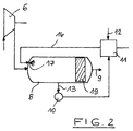
- Figure 2 shows a further embodiment of the invention Device that differs from the device of the figure 1 only by a differently designed humidification device 8 differs. In Figure 2 is therefore only a part of the overall device shown the humidifier 8th concerns.
- the moistening device is also in the embodiment of FIG 8 designed as a horizontal container.
- the humidifier container 8 of the compressed and heated intake air and flows through water in direct current.
- both media at the left end in Figure 2 of the container inserted into this. This is done via the Heat exchanger 11 supplied heated water via line 16 and is connected to one in the area the container end wall arranged nozzle 17, in which the water is distributed as a spray.
- This spray mist sinks below, however, is from the inflowing inlet air swept away.
- a Part of the water evaporates and flows with the inlet air by means of a droplet separator arranged downstream in the container 19.
Abstract
Description
Die vorliegende Erfindung betrifft eine Vorrichtung zur Zuführung von Dampf zur Einlaßluft, die einer Brennkraftmaschine zugeführt wird, mit einer Befeuchtungseinrichtung, die einen ersten Anschluß zur Zuführung von Flüssigkeit zur Befeuchtungseinrichtung und einen zweiten Anschluß zur Zuführung der Einlaßluft zur Befeuchtungseinrichtung besitzt, wobei die Befeuchtungseinrichtung die Dampfzufuhr zur Einlaßluft durch Kontakt der Einlaßluft und der Flüssigkeit miteinander bewirkt, während diese durch die Befeuchtungseinrichtung strömen, einem Vorerhitzer, der an den ersten Anschluß der Befeuchtungseinrichtung angeschlossen ist und die Flüssigkeit vor Zuführung zur Befeuchtungseinrichtung vorerhitzt, und einem an den zweiten Anschluß der Befeuchtungseinrichtung angeschlossenen Kompressor zum Komprimieren der Einlaßluft.The present invention relates to a device for feeding from steam to intake air, that of an internal combustion engine is supplied with a humidifier, which a first connection for supplying liquid for Humidifier and a second connection for feeding who has inlet air to the humidifier, the humidifier supplying steam to the intake air by contact of the inlet air and the liquid caused with each other while this by the humidifier pour a preheater to the first Connection of the humidifier is connected and the liquid before feeding to the humidifier preheated, and one to the second terminal of the humidifier connected compressor for compressing the intake air.
Eine derart ausgebildete Vorrichtung ist aus der WO 95/23 286 bekannt. Durch die Zuführung von Dampf zur Einlaßluft wird das Niveau der Stickoxidemissionen bei einer Brennkraftmaschine drastisch reduziert sowie gleichzeitig der Nutzungsgrad des Brennstoffes erhöht. Durch direkte Verdampfung der Flüssigkeit in der erhaltenen Einlaßluft ist es möglich, als speziellen Vorteil eine Selbstregulierung der Menge des Dampfes in der Einlaßluft zu erhalten, so daß daher keine separate Regulierung der Luftmenge in der Einlaßluft erforderlich ist.Such a device is from WO 95/23 286 known. By supplying steam to the intake air is the level of nitrogen oxide emissions in an internal combustion engine drastically reduced as well as the Fuel efficiency increased. By direct evaporation of the liquid in the intake air obtained self-regulation as a special advantage to get the amount of steam in the intake air so that therefore no separate regulation of the amount of air in the intake air is required.
Bei der bekannten Vorrichtung ist der Vorerhitzer entweder an das Kühlwasser oder an die Abgase der Brennkraftmaschine angeschlossen, um die im Kühlwasser oder den Abgasen steckende Energie auf die Flüssigkeit zu übertragen.In the known device, the preheater is either to the cooling water or exhaust gases from the internal combustion engine connected to those in the cooling water or exhaust gases transferring stuck energy to the liquid.
Was die Ausbildung der Befeuchtungseinrichtung bei der bekannten Vorrichtung anbetrifft, so ist diese als Befeuchtungsturm ausgebildet, den die Einlaßluft und die Flüssigkeit in entgegengesetzten Richtungen, d.h. im Gegenstrom, durchströmen, wobei die Flüssigkeit am oberen Ende und die Einlaßluft am unteren Ende in den Befeuchtungsturm eingeführt werden. Die Flüssigkeit wird über eine Düse im Befeuchtungsturm zu einem Nebel dispergiert, der durch den Befeuchtungsturm nach unten fällt und dabei durch die durch den Befeuchtungsturm nach oben strömende komprimierte und somit erhitzte Einlaßluft strömt. Hierbei wird ein Teil der Feuchtigkeit verdampft und begleitet die Einlaßluft aus dem Befeuchtungsturm heraus in die Verbrennungskammer der Brennkraftmaschine, beispielsweise einen Dieselmotor mit Turbolader.As for the training of the humidifier in the known As for the device, it is a humidification tower trained the intake air and liquid in opposite directions, i.e. countercurrent, flow through, the liquid at the top and the Inlet air introduced into the humidification tower at the lower end become. The liquid is fed through a nozzle in the humidification tower dispersed into a mist, which by the Humidification tower falls down and through it the humidification tower compressed and thus heated intake air flows. Part of the Moisture evaporates and accompanies the intake air from the Humidification tower into the combustion chamber of the Internal combustion engine, for example with a diesel engine Turbocharger.
Die Verdampfung der Flüssigkeit in einem Gasgemisch auf diese Weise bringt den Vorteil mit sich, daß sie bei wesentlich niedrigeren Temperaturen auftritt als in dem Fall, in dem nur Wasser vorhanden ist. Wenn eine starke Verdampfung bei einer relativ niedrigen Temperatur auftritt, wird es möglich, für den Verdampfungsprozeß Energie niedriger Stufe einzusetzen, die beispielsweise aus dem Kühlwasser und/oder den Abgasen der Brennkraftmaschine stammen kann. Evaporation of the liquid in a gas mixture this way has the advantage of being essential lower temperatures occurs than in the case in which there is only water. If a strong evaporation occurs at a relatively low temperature it is possible to lower energy for the evaporation process Use stage, for example from the cooling water and / or the exhaust gases from the internal combustion engine.
Wie erwähnt, ist bei der bekannten Vorrichtung die Befeuchtungseinrichtung als Befeuchtungsturm, d.h. stehender Behälter, ausgebildet. Diese Bauweise der Befeuchtungseinrichtung eignet sich besonders gut für die Führung der Einlaßluft und der Flüssigkeit im Gegenstrom. Eine derartige Bauweise der Befeuchtungseinrichtung kann jedoch manchmal zu Platzproblemen führen, insbesondere bei beengten Verhältnissen, wie sie beispielsweise auf Schiffen anzutreffen sind.As mentioned, the moistening device is in the known device as a humidification tower, i.e. standing container, educated. This design of the humidifier is particularly suitable for guiding the intake air and the liquid in countercurrent. Such Construction of the humidifier can sometimes lead to space problems, especially in confined spaces, such as those found on ships are.
Der Erfindung liegt die Aufgabe zugrunde, eine Vorrichtung der angegebenen Art zu schaffen, die in bezug auf ihre Höhenabmessungen besonders kompakt baut.The invention has for its object a device to create the specified type in relation to their height dimensions builds particularly compact.
Diese Aufgabe wird erfindungsgemäß bei einer Vorrichtung der angegebenen Art dadurch gelöst, daß die Befeuchtungseinrichtung als liegender Behälter ausgebildet ist und von der Einlaßluft und der Flüssigkeit im Kreuzstrom und/oder Gleichstrom durchströmt wird.This object is achieved in a device of the specified type in that the humidifier is designed as a horizontal container and from the intake air and the liquid in cross flow and / or Direct current is flowed through.
Durch die liegende Bauweise der Befeuchtungseinrichtung werden die vorstehend aufgezeigten Raumprobleme beseitigt. Erfindungsgemäß wurde dabei festgestellt, daß sich eine derartige liegende Bauweise für eine Gegenstromführung der Flüssigkeit und Einlaßluft nur bedingt eignet, da sich hierbei ein relativ schlechter Wirkungsgrad in bezug auf die Dampferzeugung ergibt. Dies ist verständlich, da bei einer liegenden Bauweise bei einer Führung im Gegenstrom die Flüssigkeit parallel zur Längsachse des liegenden Behälters geführt wird, jedoch durch Schwerkraft relativ rasch zum Boden des Behälters absinkt, so daß nur eine kurze Kontaktstrecke zwischen Flüssigkeit und Einlaßluft vorhanden ist. Um diesen relativ geringen Wirkungsgrad bei der Dampferzeugung zu vermeiden, schlägt die erfindungsgemäße Lösung ferner vor, daß der liegende Behälter von der Einlaßluft und der Flüssigkeit im Kreuzstrom und/oder Gleichstrom durchströmt wird.Due to the horizontal design of the humidifier the space problems shown above are eliminated. According to the invention it was found that a such lying construction for a counterflow of the Liquid and intake air are only suitable to a limited extent, since here a relatively poor efficiency in terms of the steam generation results. This is understandable since a horizontal construction with a counter-current guide the liquid parallel to the longitudinal axis of the lying container is carried out, however, by gravity relative quickly sinks to the bottom of the container so that only one short contact distance between liquid and inlet air is available. To this relatively low efficiency to avoid steam generation, the invention proposes Solution also before that the lying container of the Inlet air and the liquid in cross flow and / or Direct current is flowed through.
Wenn hier von einem "liegenden Behälter" die Rede ist, so sind damit auch geringfügig geneigte Behälterstellungen gemeint, die bis zu einer Stellung von 45° zur Horizontalen reichen.If we are talking about a "lying container", then so are also meant slightly inclined container positions, which up to a position of 45 ° to the horizontal pass.
Mit "Kreuzstrom" (cross-flow) ist gemeint, daß Flüssigkeit und Einlaßluft unter einem Winkel aufeinandertreffen, der vorzugsweise 90° beträgt, jedoch auch hiervon abweichen kann und beispielsweise in einem Bereich zwischen 45° und 135° in bezug auf die Strömungsrichtung der Einlaßluft liegen kann, wenn von einer horizontalen Durchströmung des Behälters ausgegangen wird. Natürlich kann auch die Strömungsrichtung der Einlaßluft von der Horizontalen geringfügig abweichen.By "cross flow" it is meant that liquid and intake air meet at an angle that is preferably 90 °, but also deviate therefrom can and for example in a range between 45 ° and 135 ° with respect to the flow direction of the inlet air can, if there is a horizontal flow through the container is assumed. Of course, the flow direction can also the intake air slightly from the horizontal differ.
Mit "Gleichstrom" ist gemeint, daß Einlaßluft und Flüssigkeit im wesentlichen parallel zueinander den Behälter durchströmen, wobei auch hier Abweichungen von der Parallelität möglich sind, beispielsweise bis zu einem Winkel von 45° zur Strömungsrichtung der Einlaßluft.By "direct current" it is meant that intake air and liquid the container essentially parallel to each other flow through, with deviations from parallelism are possible, for example up to an angle of 45 ° to the direction of flow of the intake air.
Bei einem idealen Kreuzstrom, d.h. bei oben in den Behälter eingeführter Flüssigkeit und den Behälter horizontal durchströmender Einlaßluft, entspricht die Kontaktstrecke zwischen beiden Medien maximal der Behälterhöhe. Durch die seitlich auf die eingeführte Flüssigkeit auftreffende Einlaßluft wird jedoch die Flüssigkeit in Längsrichtung des Behälters mitgerissen, so daß die tatsächliche Kontaktstrecke länger ist. Hierdurch wird ein relativ guter Wirkungsgrad erzielt. With an ideal cross current, i.e. at the top in the container introduced liquid and horizontally flowing through the container Intake air, corresponds to the contact distance between maximum of the container height for both media. Through the Inlet air impinging laterally on the introduced liquid however, the liquid will flow in the longitudinal direction of the Container carried along, so that the actual contact distance is longer. This will make it a relatively good one Efficiency achieved.
Beim Gleichstrom, bei dem Flüssigkeit und Einlaßluft parallel zueinander in gleicher Richtung durch den liegenden Behälter geführt werden, entstehen die bei einer Gegenstromführung auftretenden Probleme nicht, da die eingeführte Flüssigkeit vom Einlaßluftstrom mitgerissen und über die Länge des Behälters mitgeführt wird, so daß sich auch hier eine relativ lange Kontaktstrecke ergibt, die zu einem guten Wirkungsgrad führt.With direct current, with liquid and inlet air in parallel to each other in the same direction through the lying container are created in a countercurrent flow problems do not arise since the introduced Liquid entrained by the intake air flow and over the Length of the container is carried, so that here too a relatively long contact distance results in one good efficiency.
In beiden Fällen wird jedenfalls eine in bezug auf die Höhe der Vorrichtung platzsparende Bauweise erreicht, ohne daß gegenüber dem Stand der Technik eine Verschlechterung des Wirkungsgrades bei der Dampfbildung in Kauf genommen werden muß.In either case, one will be in terms of height the device space-saving design achieved without a deterioration of the prior art Efficiency in steam formation can be accepted got to.
In Weiterbildung der Erfindung weist die Befeuchtungseinrichtung mindestens eine an den ersten Anschluß angeschlossene Düse zum Verteilen der Flüssigkeit im Behälter auf. Diese Düse ist, je nach Strömungsführung (Kreuzstrom oder Gegenstrom), im oberen Bereich oder im vorderen Bereich (Eintrittsbereich) des liegenden Behälters angeordnet. Die Flüssigkeit wird mit Hilfe der Düse zu einem Nebel zerstäubt, der nach unten fällt, hierbei mit der Einlaßluft in Kontakt tritt und am Boden der Befeuchtungseinrichtung gesammelt wird. Von hier aus kann er über eine Leitung zu einem Flüssigkeitstank zurückgeführt werden, aus dem die Flüssigkeit auch entnommen wird.In a development of the invention, the humidification device has at least one connected to the first port Nozzle for distributing the liquid in the container. This nozzle is, depending on the flow direction (cross flow or Counterflow), in the upper area or in the front area (Entry area) of the lying container. The Liquid is atomized into a mist using the nozzle, which falls down, with the intake air in Contact occurs and collected on the bottom of the humidifier becomes. From here it can be accessed via a line be returned to a liquid tank from which the Liquid is also removed.
Da der Behälter bei liegender Bauweise zweckmäßigerweise eine relativ große Länge besitzt, hat es sich als besonders günstig erwiesen, bei Führung der Flüssigkeit im Kreuzstrom, mehrere Düsen im oberen Bereich des Behälters in Strömungsrichtung der Einlaßluft hintereinander anzuordnen, so daß der Einlaßluft auf ihrem Wege durch den Behälter in entsprechenden Behälterabschnitten immer neue Flüssigkeit zugeführt wird. Auf diese Weise kann ein besonders großer Anteil der Flüssigkeit verdampft werden.Since the container expediently in a lying construction has a relatively large length, it has turned out to be special proved to be favorable when the liquid is carried in cross flow, several nozzles in the upper part of the tank To arrange the flow direction of the inlet air one behind the other, so that the intake air in on its way through the container appropriate liquid sections always new liquid is fed. In this way, a particularly large one Portion of the liquid to be evaporated.
Eine weitere bevorzugte Lösung der Erfindung besteht darin, daß die Befeuchtungseinrichtung mindestens einen Füllkörperblock aufweist. Hiermit läßt sich die Befeuchtungsleistung weiter steigern. Geeignete Füllkörpermaterialien sind bekannt und müssen an dieser Stelle nicht im einzelnen aufgeführt werden.Another preferred solution of the invention consists in that the moistening device has at least one packing block having. This allows the humidification performance further increase. Suitable packing materials are known and need not be listed in detail here become.
Zweckmäßigerweise sind in Luftströmungsrichtung hintereinander mehrere Füllkörperblöcke im Behälter angeordnet. Bei einer Strömungsführung im Kreuzstrom kann jeder Füllkörperblock von oben über eine zugehörige Düse mit einem entsprechenden Flüssigkeitsnebel beaufschlagt werden. Diese hintereinander angeordneten Füllkörperblöcke werden von der Einlaßluft in Horizontalrichtung durchströmt, wobei in jedem Füllkörperblockbereich eine entsprechende Flüssigkeitsverdampfung stattfindet. Bei dieser Ausführungsform ergeben sich zusätzlich Steuerungsmöglichkeiten, da, falls gewünscht, bestimmte Füllkörperblöcke mit geringerer Leistung gefahren bzw. ganz stillgelegt werden können.Expediently one behind the other in the air flow direction several packing blocks arranged in the container. At Each packing block can flow in a cross flow from above via an associated nozzle with a corresponding one Liquid mist can be applied. This one after the other Arranged packing blocks are used by the Inlet air flows in the horizontal direction, being in each Packing block area a corresponding liquid evaporation takes place. Result in this embodiment additional control options, since, if desired, certain packing blocks with lower performance can be driven or completely shut down.
Wahlweise kann der Behälter mit einem Tropfenabscheider ausgestattet sein, zweckmäßigerweise im abstromseitigen Bereich des Behälters und nach den Füllkörperblöcken, falls solche vorhanden sind.The container can optionally be equipped with a droplet separator be equipped, expediently in the downstream area of the container and after the packing blocks, if there are such.
Bei der verwendeten Flüssigkeit handelt es sich vorzugsweise um Wasser, so daß der Einlaßluft der Brennkraftmaschine Wasserdampf zugeführt wird. Natürlich kann anstelle von Wasser auch jede gewünschte und geeignete andere Flüssigkeit verdampft werden. Auch die Düse, die die Flüssigkeit dispergiert, kann beispielsweise durch eine Anordnung ersetzt werden, über die oder durch die, je nach ihrer Ausführungsform, die Flüssigkeit zum Boden der Befeuchtungseinrichtung strömt.The liquid used is preferably to water so that the intake air of the internal combustion engine Steam is supplied. Of course, instead of of water also any desired and suitable other liquid be evaporated. Even the nozzle that holds the liquid dispersed, for example, by an arrangement be replaced, over or by, depending on their Embodiment, the liquid to the bottom of the humidifier flows.
Im übrigen wird in bezug auf weitere Einzelheiten der Vorrichtung auf die vorstehend erwähnte WO 95/23 286 Bezug genommen, deren Offenbarung durch Bezugnahme in die vorliegende Anmeldung eingearbeitet wird.Incidentally, regarding further details of the device referred to the aforementioned WO 95/23 286, the disclosure of which by reference to the present Registration is incorporated.
Die Erfindung wird nachfolgend anhand von zwei Ausführungsbeispielen in Verbindung mit der Zeichnung im einzelnen erläutert. Es zeigen:
- Figur 1
- eine schematische Darstellung einer Brennkraftmaschine mit einer hieran angeschlossenen Vorrichtung zur Zuführung von Dampf zur Einlaßluft gemäß einer ersten Ausführungsform der Erfindung; und
Figur 2- die Befeuchtungseinrichtung einer Vorrichtung zur Zuführung von Dampf zur Einlaßluft der Brennkraftmaschine gemäß einer zweiten Ausführungsform der vorliegenden Erfindung.
- Figure 1
- is a schematic representation of an internal combustion engine with an attached device for supplying steam to the intake air according to a first embodiment of the invention; and
- Figure 2
- the humidifier of a device for supplying steam to the intake air of the internal combustion engine according to a second embodiment of the present invention.
Figur 1 zeigt eine Brennkraftmaschine 1 mit sechs Zylindern
2. Bei der Brennkraftmaschine handelt es sich um einen Dieselmotor
mit Turbolader. Der Turbolader umfaßt eine Turbine
3, die an die Abgasseite des Motors 1 über eine Abgasleitung
4 angeschlossen ist. Die Turbine steht über eine Welle
5 mit einem Kompressor 6 in Verbindung und treibt diesen
an, um die dem Motor 1 auf der Einlaßseite desselben über
eine erste Luftleitung 7 zugeführte Luft zu komprimieren.
Zwischen dem Kompressor 6 und dem Motor 1 ist eine Befeuchtungseinrichtung
8 angeordnet, die dazu dient, Wasserdampf
der Einlaßluft zuzuführen, bevor diese über eine zweite
Luftleitung 9 dem Motor zugeführt wird. Der Wasserdampf
wird aus Wasser von einem Tank 10, das über einen Wärmetauscher
11 der Befeuchtungseinrichtung 8 zugeführt wird, erzeugt.
Im Wärmetauscher 11 wird das Wasser durch das Kühlwasser
des Motors, das über eine Leitung 12 durch den Wärmetauscher
11 zirkuliert, erhitzt.Figure 1 shows an internal combustion engine 1 with six
Es wird nunmehr die Ausbildung der Befeuchtungseinrichtung
8 erläutert. Diese ist als liegender Behälter ausgebildet.
Er ist in Richtung seiner Längsachse in drei Abteile aufgeteilt,
die jeweils einen Füllkörperblock 18 enthalten. In
Strömungsrichtung der Einlaßluft, d.h. in Figur 1 von links
nach rechts, sind daher drei Füllkörperblöcke 18 hintereinander
angeordnet.It will now be the formation of the
Im in Figur 1 linken Endbereich des Behälters befindet sich
ein Anschluß für die vom Kompressor 6 kommende Einlaßluftleitung
7. Über diesen Anschluß wird komprimierte und erhitzte
Einlaßluft in den Behälter eingeführt, so daß sie
diesen etwa horizontal und parallel zu seiner Längsachse
durchströmt.Located in the left end region of the container in FIG. 1
a connection for the inlet air line coming from the
Im oberen Bereich des Behälters befinden sich drei Anschlüsse
für die vom Wärmetauscher 11 kommende Wasserleitung
16. Diese Anschlüsse führen zu drei Düsen 17, wobei
sich jeweils eine Düse 17 über einem Füllkörperblock 18 befindet.
Das zugeführte Wasser wird über die Düsen 17 zu
einem Nebel verteilt, der über den entsprechenden Füllkörperblock
18 strömt und dabei mit der den Füllkörperblock
horzizontal durchströmenden Einlaßluft in Kontakt tritt.
Hierdurch wird ein Teil des Wassernebels verdampft und mit
der Einlaßluft mitgeführt, die über einen am in Figur 1
rechten Endbereich des Behälters angeordneten Auslaß zur
Leitung 9 gelangt, mit der die mit Dampf versehene Einlaßluft
der Brennkraftmaschine zugeführt wird. There are three connections in the upper area of the container
for the water pipe coming from the
Der nicht verdampfte Wasseranteil sammelt sich am Boden des
Behälters und wird dort über eine Leitung 13 zu einem Tank
10 abgeführt. Aus diesem Tank wird das Wasser zum Wärmetauscher
11 geführt.The non-evaporated water part collects at the bottom of the
Container and is there via a
In der Befeuchtungseinrichtung 18 treffen somit erhitztes
Wasser und erhitzte und komprimierte Einlaßluft im Kreuzstrom
aufeinander.In the
Die Vorrichtung funktioniert in der folgenden Weise:The device works in the following way:
Die Einlaßluft wird im Kompressor 6, der über die Welle 5
von der Turbine 3 angetrieben wird, die wiederum von den
Abgasen des Motors 1 angetrieben wird, komprimiert. Die
komprimierte und somit erhitzte Einlaßluft wird in Figur 1
von links in die Befeuchtungseinrichtung 8 eingeführt und
durchströmt diese in Horizontalrichtung. Dabei durchdringt
sie die vorgesehenen Füllkörperblöcke 18 und wird über das
am Boden der Befeuchtungseinrichtung 8 angesammelte Wasser
geführt. Wasser wird aus dem Tank 10 genommen und über den
Wärmetauscher 11 in den oberen Teil der Befeuchtungseinrichtung
8 geführt, wo es über die drei Düsen 17 auf die
Füllkörperblöcke 18 versprüht wird. Während das Wasser
durch die Füllkörperblöcke 18 nach unten fällt, strömt es
durch die die Füllkörperblöcke horizontal durchströmende
Einlaßluft. Ein Teil des Wassers wird verdampft und begleitet
die Einlaßluft aus der Befeuchtungseinrichtung 8 heraus
in die Verbrennungskammer des Motors 1. Im Vergleich zu dem
Wasserstrom, der verdampft wird, wird somit ein signifikant
größerer Wasserstrom der Befeuchtungseinrichtung zugeführt.
Folglich wird die Verdampfungsenergie vom tatsächlichen
Wasser entnommen. Wenn die Verdampfung des Wassers in einem
Gasgemisch auf diese Weise durchgeführt wird, tritt die
Verdampfung bei wesentlich niedrigeren Temperaturen auf als
in dem Fall, in dem nur Wasser vorhanden ist. Dies
impliziert, daß die Verdampfung nahe bei dem Punkt, bei dem
die Luft der Befeuchtungseinrichtung 8 zugeführt wird, bei
einer sehr niedrigen Temperatur auftritt und durch die Befeuchtungseinrichtung
8 in Strömungsrichtung der Einlaßluft
mit ansteigenden Feuchtigkeitsanteil und somit ansteigendem
Partialdruck ansteigt. Wenn eine starke Verdampfung bei
einer relativ niedrigen Temperatur auftritt, wird es möglich,
für den Verdampfungsprozeß Energie niedriger Stufe
einzusetzen. Derartige Energie niedriger Stufe wird in
großen Mengen als Überschußwärme vom Motor 1 im Kühlwasser
oder in den Abgasen gewonnen. Somit können das Kühlwasser,
die Abgase oder beide zum Vorerhitzen des Wassers im Wärmetauscher
11 eingesetzt werden, bevor dieses der Befeuchtungseinrichtung
8 zugeführt wird.The intake air is in the
Es sei noch erwähnt, daß Kraftstoff dem Motor 1 über eine
Kraftstoffleitung 14 zugeführt wird. Ferner ist der Motor
an einen Generator 15 angeschlossen.It should also be mentioned that fuel the engine 1 via a
Figur 2 zeigt eine weitere Ausführungsform der erfindungsgemäßen
Vorrichtung, die sich von der Vorrichtung der Figur
1 nur durch eine anders augebildete Befeuchtungseinrichtung
8 unterscheidet. In Figur 2 ist daher nur ein Teil der Gesamtvorrichtung
gezeigt, der die Befeuchtungseinrichtung 8
betrifft.Figure 2 shows a further embodiment of the invention
Device that differs from the device of the figure
1 only by a differently designed
Auch bei der Ausführungsform der Figur 2 ist die Befeuchtungseinrichtung
8 als liegender Behälter ausgebildet. Bei
dieser Ausführungsform wird der Behälter der Befeuchtungseinrichtung
8 von der komprimierten und erhitzten Einlaßluft
und von Wasser im Gleichstrom durchströmt. Wie Figur 2
zeigt, werden beide Medien am in Figur 2 linken Endbereich
des Behälters in diesen eingeführt. Dabei wird das über den
Wärmetauscher 11 erhitzte Wasser über die Leitung 16 zugeführt
und gelangt über einen Anschluß zu einer im Bereich
der Behälterendwand angeordneten Düse 17, in der das Wasser
als Sprühnebel verteilt wird. Dieser Sprühnebel sinkt nach
unten, wird dabei jedoch von der einströmenden Einlaßluft
mitgerissen. Durch Kontaktierung beider Medien wird ein
Teil des Wassers verdampft und strömt mit der Einlaßluft
durch einen stromab im Behälter angeordneten Tropfenabscheider
19. Durch diesen Tropfenabscheider werden die im
Luftstrom mitgeführten und nicht verdampften Tropfen abgeschieden,
im unteren Teil des Tropfenabscheiders gesammelt
und gelangen zusammen mit dem im übrigen Teil des Behälters
nicht verdampften Wasser über eine Ablaufleitung 13 in
einen Wassertank 10. Aus diesem Wassertank 10 wird das über
den Wärmetauscher 11 zugeführte Wasser entnommen. Die den
Wasserdampf mitführende Einlaßluft wird über die Leitung 9
aus dem Behälter abgeführt und der Brennkraftmaschine zugeführt.The moistening device is also in the embodiment of FIG
8 designed as a horizontal container. At
In this embodiment, the
Claims (8)
Priority Applications (1)
| Application Number | Priority Date | Filing Date | Title |
|---|---|---|---|
| DK98121359T DK0916836T3 (en) | 1997-11-13 | 1998-11-10 | Device for supplying steam to the inlet air of a combustion engine |
Applications Claiming Priority (2)
| Application Number | Priority Date | Filing Date | Title |
|---|---|---|---|
| DE19750181 | 1997-11-13 | ||
| DE19750181A DE19750181C2 (en) | 1997-11-13 | 1997-11-13 | Device for supplying steam to the intake air of an internal combustion engine |
Publications (3)
| Publication Number | Publication Date |
|---|---|
| EP0916836A2 true EP0916836A2 (en) | 1999-05-19 |
| EP0916836A3 EP0916836A3 (en) | 2000-03-08 |
| EP0916836B1 EP0916836B1 (en) | 2004-07-28 |
Family
ID=7848530
Family Applications (1)
| Application Number | Title | Priority Date | Filing Date |
|---|---|---|---|
| EP98121359A Expired - Lifetime EP0916836B1 (en) | 1997-11-13 | 1998-11-10 | Device for admitting vapour to the intake air of a combustion engine |
Country Status (6)
| Country | Link |
|---|---|
| EP (1) | EP0916836B1 (en) |
| AT (1) | ATE272170T1 (en) |
| DE (2) | DE19750181C2 (en) |
| DK (1) | DK0916836T3 (en) |
| ES (1) | ES2227756T3 (en) |
| PT (1) | PT916836E (en) |
Cited By (6)
| Publication number | Priority date | Publication date | Assignee | Title |
|---|---|---|---|---|
| EP1076169A2 (en) * | 1999-08-12 | 2001-02-14 | Munters Euroform GmbH | Device for humidifying the intake air of a turbocharged combustion engine |
| EP1205659A3 (en) * | 2000-11-03 | 2002-09-11 | Wärtsilä Technology Oy AB | Method of reducing nitrogen oxide (NOX) emissions of super-charged piston engine |
| WO2002075141A1 (en) * | 2001-03-20 | 2002-09-26 | Munters Euroform Gmbh | Device for humidifying the intake air of an internal combustion engine, which is equipped with a turbocharger, involving pre-heating effected by a water circuit |
| WO2003078819A1 (en) * | 2002-03-20 | 2003-09-25 | Wärtsilä Finland Oy | METHOD OF REDUCING NITROGEN OXIDE (NOx) EMISSIONS IN SUPERCHARGED PISTON ENGINE AND PISTON ENGINE ARRANGEMENT |
| WO2005031144A1 (en) * | 2003-09-24 | 2005-04-07 | Munters Euroform Gmbh | Combustion engine unit comprising a humidifying device |
| WO2005038229A1 (en) * | 2003-10-15 | 2005-04-28 | Wärtsilä Finland Oy | A method of reducing the nitrogen oxide emissions (nox) of a supercharged piston engine and a piston engine arrangement |
Families Citing this family (3)
| Publication number | Priority date | Publication date | Assignee | Title |
|---|---|---|---|---|
| DE10204181C1 (en) * | 2002-02-01 | 2003-10-09 | Man B & W Diesel Ag | Motor vehicle reciprocating piston internal combustion engine, has water injector between turbocharger and intercooler to reduce pollution |
| FI118136B (en) * | 2002-04-19 | 2007-07-13 | Marioff Corp Oy | Injection procedure and apparatus |
| DE102011005595A1 (en) * | 2011-03-16 | 2012-09-20 | Bayerische Motoren Werke Aktiengesellschaft | Method for performing condensation using operation of air conditioning apparatus of vehicle i.e. motor car, involves using condensed water for cooling vehicle component i.e. prime mover, of vehicle |
Citations (1)
| Publication number | Priority date | Publication date | Assignee | Title |
|---|---|---|---|---|
| WO1995023286A1 (en) | 1994-02-25 | 1995-08-31 | Rosen Per | Method for supplying vapour to the intake air of an internal combustion engine, and device therefor |
Family Cites Families (8)
| Publication number | Priority date | Publication date | Assignee | Title |
|---|---|---|---|---|
| DE570904C (en) * | 1929-08-04 | 1933-02-22 | Gustav Schlick | Process for forming a mixture of air, finely atomized fuel and water |
| ES122183A1 (en) * | 1930-03-25 | 1931-04-16 | Albert Kurt | PROCEDURE FOR COMBUSTION ENGINE SERVICE |
| US1854607A (en) * | 1930-05-15 | 1932-04-19 | Andrews Albert | Engine-cooling and supercharging means |
| DE2738807A1 (en) * | 1977-08-29 | 1979-03-15 | Henry C Linder | Fuel expanded for vehicle IC engine - has fuel heated by exchange with valve regulated flows of hot and cold water |
| DE3339759A1 (en) * | 1983-11-03 | 1985-05-15 | Franz X. 6200 Wiesbaden Wittek | Process and preparation system for the production of an ignitable fuel-air mixture for internal combustion engines |
| US4960080A (en) * | 1989-02-28 | 1990-10-02 | Cummins Engine Company, Inc. | Pollution control apparatus and method for a turbodiesel motor-generator set |
| DK170217B1 (en) * | 1993-06-04 | 1995-06-26 | Man B & W Diesel Gmbh | Large pressurized internal combustion engine and method of operating a cooler for cooling such engine's intake air. |
| DE19538067A1 (en) * | 1995-10-13 | 1997-04-17 | Erdgas En Systeme Gmbh | Stationary internal combustion engine and method for its operation |
-
1997
- 1997-11-13 DE DE19750181A patent/DE19750181C2/en not_active Expired - Lifetime
-
1998
- 1998-11-10 ES ES98121359T patent/ES2227756T3/en not_active Expired - Lifetime
- 1998-11-10 PT PT98121359T patent/PT916836E/en unknown
- 1998-11-10 DK DK98121359T patent/DK0916836T3/en active
- 1998-11-10 AT AT98121359T patent/ATE272170T1/en active
- 1998-11-10 EP EP98121359A patent/EP0916836B1/en not_active Expired - Lifetime
- 1998-11-10 DE DE59811711T patent/DE59811711D1/en not_active Expired - Fee Related
Patent Citations (1)
| Publication number | Priority date | Publication date | Assignee | Title |
|---|---|---|---|---|
| WO1995023286A1 (en) | 1994-02-25 | 1995-08-31 | Rosen Per | Method for supplying vapour to the intake air of an internal combustion engine, and device therefor |
Cited By (11)
| Publication number | Priority date | Publication date | Assignee | Title |
|---|---|---|---|---|
| EP1076169A2 (en) * | 1999-08-12 | 2001-02-14 | Munters Euroform GmbH | Device for humidifying the intake air of a turbocharged combustion engine |
| EP1076169A3 (en) * | 1999-08-12 | 2001-10-10 | Munters Euroform GmbH | Device for humidifying the intake air of a turbocharged combustion engine |
| EP1205659A3 (en) * | 2000-11-03 | 2002-09-11 | Wärtsilä Technology Oy AB | Method of reducing nitrogen oxide (NOX) emissions of super-charged piston engine |
| WO2002075141A1 (en) * | 2001-03-20 | 2002-09-26 | Munters Euroform Gmbh | Device for humidifying the intake air of an internal combustion engine, which is equipped with a turbocharger, involving pre-heating effected by a water circuit |
| WO2003078819A1 (en) * | 2002-03-20 | 2003-09-25 | Wärtsilä Finland Oy | METHOD OF REDUCING NITROGEN OXIDE (NOx) EMISSIONS IN SUPERCHARGED PISTON ENGINE AND PISTON ENGINE ARRANGEMENT |
| US7178486B2 (en) | 2002-03-20 | 2007-02-20 | Wartsila Finland Oy | Method of reducing nitrogen oxide (NOx) emissions in supercharged piston engine and piston engine arrangement |
| KR100965321B1 (en) | 2002-03-20 | 2010-06-22 | 바르실라 핀랜드 오이 | METHOD OF REDUCING NITROGEN OXIDENOx EMISSIONS IN SUPERCHARGED PISTON ENGINE AND PISTON ENGINE ARRANGEMENT |
| WO2005031144A1 (en) * | 2003-09-24 | 2005-04-07 | Munters Euroform Gmbh | Combustion engine unit comprising a humidifying device |
| WO2005038229A1 (en) * | 2003-10-15 | 2005-04-28 | Wärtsilä Finland Oy | A method of reducing the nitrogen oxide emissions (nox) of a supercharged piston engine and a piston engine arrangement |
| CN100408842C (en) * | 2003-10-15 | 2008-08-06 | 瓦特西拉芬兰有限公司 | A method of reducing the nitrogen oxide emissions(NOx) of a supercharged piston engine and a piston engine arrangement |
| KR101110924B1 (en) | 2003-10-15 | 2012-04-12 | 바르실라 핀랜드 오이 | A METHOD OF REDUCING THE NITROGEN OXIDE EMISSIONSNOx OF A SUPERCHARGED PISTON ENGINE AND A PISTON ENGINE ARRANGEMENT |
Also Published As
| Publication number | Publication date |
|---|---|
| ATE272170T1 (en) | 2004-08-15 |
| EP0916836A3 (en) | 2000-03-08 |
| DE19750181A1 (en) | 1999-05-27 |
| DE59811711D1 (en) | 2004-09-02 |
| PT916836E (en) | 2004-12-31 |
| DK0916836T3 (en) | 2004-12-06 |
| EP0916836B1 (en) | 2004-07-28 |
| ES2227756T3 (en) | 2005-04-01 |
| DE19750181C2 (en) | 2000-06-21 |
Similar Documents
| Publication | Publication Date | Title |
|---|---|---|
| DE69836910T2 (en) | DEVICE FOR A GAS TURBINE | |
| DE602004011762T2 (en) | METHOD FOR OPERATING A GAS TURBINE GROUP | |
| DE69919821T2 (en) | DEVICE FOR COMPRESSING A GASEOUS MEDIUM AND SYSTEMS CONTAINING SUCH A DEVICE | |
| DE2163938A1 (en) | Device for vaporizing fuel | |
| DE10330859A1 (en) | Operating emission-free gas turbine power plant involves feeding some compressed circulated gas directly to combustion chamber, cooling/humidifying some gas before feeding to combustion chamber | |
| DE3120098C2 (en) | Liquid heater | |
| DE8204570U1 (en) | AIR COOLED STEAM CONDENSER | |
| EP0916836B1 (en) | Device for admitting vapour to the intake air of a combustion engine | |
| DE19717267A1 (en) | Process for processing frozen liquid gas | |
| EP0939288A1 (en) | Condensation system | |
| DE1140957B (en) | Absorption refrigeration system and method for operating the same | |
| DE69829870T2 (en) | DEVICE FOR COOLING GASES | |
| EP0597325A1 (en) | Method of compressor intercooling | |
| DE2931178A1 (en) | Gas turbine energy conversion system - comprising open or closed process, using isothermal compression, e.g. for solar power plant | |
| WO2019096481A1 (en) | Humidification system, and fuel cell system comprising a humidification system | |
| DE1019861B (en) | Additional device for carburettor engines | |
| DE10204181C1 (en) | Motor vehicle reciprocating piston internal combustion engine, has water injector between turbocharger and intercooler to reduce pollution | |
| DE3418699A1 (en) | DEVICE FOR GENERATING INJECTION GAS, PREFERRED FOR DRIVING OIL OUT OF WAREHOUSE | |
| DE60300583T2 (en) | Air supply system for an internal combustion engine | |
| EP0908676B1 (en) | Method and device for operating a boiler fired with liquid or gaseous hydrocarbons | |
| DE2139766A1 (en) | ||
| DE4303514A1 (en) | Device for reducing pollutant emissions in motor vehicles | |
| DE10060788A1 (en) | Method and arrangement for providing an ignitable working gas from a cryogenic fuel | |
| DE19804989B4 (en) | Method and device for preheating combustion air supplied to a burner of a combustion system | |
| EP0935096A1 (en) | Method and device for supplying combustion air to the burner of a combustion plant |
Legal Events
| Date | Code | Title | Description |
|---|---|---|---|
| PUAI | Public reference made under article 153(3) epc to a published international application that has entered the european phase |
Free format text: ORIGINAL CODE: 0009012 |
|
| AK | Designated contracting states |
Kind code of ref document: A2 Designated state(s): AT BE CH DE DK ES FR GB IE IT LI NL PT SE |
|
| AX | Request for extension of the european patent |
Free format text: AL;LT;LV;MK;RO;SI |
|
| RIN1 | Information on inventor provided before grant (corrected) |
Inventor name: WETTERGARD, JAN Inventor name: ROSEN, PER |
|
| PUAL | Search report despatched |
Free format text: ORIGINAL CODE: 0009013 |
|
| AK | Designated contracting states |
Kind code of ref document: A3 Designated state(s): AT BE CH CY DE DK ES FI FR GB GR IE IT LI LU MC NL PT SE |
|
| AX | Request for extension of the european patent |
Free format text: AL;LT;LV;MK;RO;SI |
|
| 17P | Request for examination filed |
Effective date: 20000907 |
|
| AKX | Designation fees paid |
Free format text: AT BE CH DE DK ES FR GB IE IT LI NL PT SE |
|
| 17Q | First examination report despatched |
Effective date: 20021128 |
|
| GRAP | Despatch of communication of intention to grant a patent |
Free format text: ORIGINAL CODE: EPIDOSNIGR1 |
|
| GRAS | Grant fee paid |
Free format text: ORIGINAL CODE: EPIDOSNIGR3 |
|
| GRAA | (expected) grant |
Free format text: ORIGINAL CODE: 0009210 |
|
| RIN1 | Information on inventor provided before grant (corrected) |
Inventor name: WETTERGARD, JAN Inventor name: ROSEN, PER |
|
| AK | Designated contracting states |
Kind code of ref document: B1 Designated state(s): AT BE CH DE DK ES FR GB IE IT LI NL PT SE |
|
| REG | Reference to a national code |
Ref country code: GB Ref legal event code: FG4D Free format text: NOT ENGLISH |
|
| REG | Reference to a national code |
Ref country code: CH Ref legal event code: EP |
|
| REG | Reference to a national code |
Ref country code: IE Ref legal event code: FG4D Free format text: GERMAN |
|
| REF | Corresponds to: |
Ref document number: 59811711 Country of ref document: DE Date of ref document: 20040902 Kind code of ref document: P |
|
| REG | Reference to a national code |
Ref country code: SE Ref legal event code: TRGR |
|
| REG | Reference to a national code |
Ref country code: DK Ref legal event code: T3 |
|
| GBT | Gb: translation of ep patent filed (gb section 77(6)(a)/1977) |
Effective date: 20041203 |
|
| REG | Reference to a national code |
Ref country code: PT Ref legal event code: SC4A Free format text: AVAILABILITY OF NATIONAL TRANSLATION Effective date: 20041028 |
|
| REG | Reference to a national code |
Ref country code: CH Ref legal event code: NV Representative=s name: HEPP, WENGER & RYFFEL AG |
|
| REG | Reference to a national code |
Ref country code: ES Ref legal event code: FG2A Ref document number: 2227756 Country of ref document: ES Kind code of ref document: T3 |
|
| PG25 | Lapsed in a contracting state [announced via postgrant information from national office to epo] |
Ref country code: DE Free format text: LAPSE BECAUSE OF NON-PAYMENT OF DUE FEES Effective date: 20050601 |
|
| PLBE | No opposition filed within time limit |
Free format text: ORIGINAL CODE: 0009261 |
|
| STAA | Information on the status of an ep patent application or granted ep patent |
Free format text: STATUS: NO OPPOSITION FILED WITHIN TIME LIMIT |
|
| ET | Fr: translation filed | ||
| 26N | No opposition filed |
Effective date: 20050429 |
|
| PG25 | Lapsed in a contracting state [announced via postgrant information from national office to epo] |
Ref country code: IT Free format text: LAPSE BECAUSE OF NON-PAYMENT OF DUE FEES Effective date: 20051110 |
|
| PGRI | Patent reinstated in contracting state [announced from national office to epo] |
Ref country code: IT Effective date: 20091201 |
|
| REG | Reference to a national code |
Ref country code: FR Ref legal event code: PLFP Year of fee payment: 18 |
|
| REG | Reference to a national code |
Ref country code: FR Ref legal event code: PLFP Year of fee payment: 19 |
|
| REG | Reference to a national code |
Ref country code: FR Ref legal event code: PLFP Year of fee payment: 20 |
|
| PGFP | Annual fee paid to national office [announced via postgrant information from national office to epo] |
Ref country code: DK Payment date: 20171115 Year of fee payment: 20 Ref country code: NL Payment date: 20171115 Year of fee payment: 20 Ref country code: FR Payment date: 20171117 Year of fee payment: 20 |
|
| PGFP | Annual fee paid to national office [announced via postgrant information from national office to epo] |
Ref country code: PT Payment date: 20171103 Year of fee payment: 20 Ref country code: IT Payment date: 20171123 Year of fee payment: 20 Ref country code: AT Payment date: 20171128 Year of fee payment: 20 Ref country code: BE Payment date: 20171116 Year of fee payment: 20 Ref country code: ES Payment date: 20171201 Year of fee payment: 20 Ref country code: SE Payment date: 20171115 Year of fee payment: 20 Ref country code: GB Payment date: 20171108 Year of fee payment: 20 Ref country code: IE Payment date: 20171103 Year of fee payment: 20 |
|
| PGFP | Annual fee paid to national office [announced via postgrant information from national office to epo] |
Ref country code: CH Payment date: 20180125 Year of fee payment: 20 |
|
| REG | Reference to a national code |
Ref country code: DK Ref legal event code: EUP Effective date: 20181110 |
|
| REG | Reference to a national code |
Ref country code: NL Ref legal event code: MK Effective date: 20181109 |
|
| REG | Reference to a national code |
Ref country code: CH Ref legal event code: PL |
|
| REG | Reference to a national code |
Ref country code: GB Ref legal event code: PE20 Expiry date: 20181109 |
|
| REG | Reference to a national code |
Ref country code: BE Ref legal event code: MK Effective date: 20181110 |
|
| REG | Reference to a national code |
Ref country code: AT Ref legal event code: MK07 Ref document number: 272170 Country of ref document: AT Kind code of ref document: T Effective date: 20181110 |
|
| REG | Reference to a national code |
Ref country code: IE Ref legal event code: MK9A |
|
| REG | Reference to a national code |
Ref country code: SE Ref legal event code: EUG |
|
| PG25 | Lapsed in a contracting state [announced via postgrant information from national office to epo] |
Ref country code: IE Free format text: LAPSE BECAUSE OF EXPIRATION OF PROTECTION Effective date: 20181110 Ref country code: PT Free format text: LAPSE BECAUSE OF EXPIRATION OF PROTECTION Effective date: 20181119 |
|
| PG25 | Lapsed in a contracting state [announced via postgrant information from national office to epo] |
Ref country code: GB Free format text: LAPSE BECAUSE OF EXPIRATION OF PROTECTION Effective date: 20181109 |
|
| REG | Reference to a national code |
Ref country code: ES Ref legal event code: FD2A Effective date: 20200803 |
|
| PG25 | Lapsed in a contracting state [announced via postgrant information from national office to epo] |
Ref country code: ES Free format text: LAPSE BECAUSE OF EXPIRATION OF PROTECTION Effective date: 20181111 |