EP0916535B1 - Device and method for hydraulically operating moving parts - Google Patents
Device and method for hydraulically operating moving parts Download PDFInfo
- Publication number
- EP0916535B1 EP0916535B1 EP98890280A EP98890280A EP0916535B1 EP 0916535 B1 EP0916535 B1 EP 0916535B1 EP 98890280 A EP98890280 A EP 98890280A EP 98890280 A EP98890280 A EP 98890280A EP 0916535 B1 EP0916535 B1 EP 0916535B1
- Authority
- EP
- European Patent Office
- Prior art keywords
- pressure
- piston
- operating arrangement
- working cylinder
- cylinder
- Prior art date
- Legal status (The legal status is an assumption and is not a legal conclusion. Google has not performed a legal analysis and makes no representation as to the accuracy of the status listed.)
- Expired - Lifetime
Links
- 238000000034 method Methods 0.000 title claims description 21
- 238000012544 monitoring process Methods 0.000 claims description 7
- 239000012530 fluid Substances 0.000 claims description 6
- 230000007246 mechanism Effects 0.000 claims description 6
- 238000011156 evaluation Methods 0.000 claims description 5
- 238000007789 sealing Methods 0.000 claims description 3
- 238000010276 construction Methods 0.000 claims description 2
- 230000004075 alteration Effects 0.000 claims 1
- 230000008569 process Effects 0.000 description 13
- 238000004519 manufacturing process Methods 0.000 description 6
- 230000008859 change Effects 0.000 description 5
- 238000007373 indentation Methods 0.000 description 5
- 230000008901 benefit Effects 0.000 description 4
- 238000010586 diagram Methods 0.000 description 4
- 230000000694 effects Effects 0.000 description 4
- 238000013461 design Methods 0.000 description 3
- 230000009471 action Effects 0.000 description 2
- 230000009467 reduction Effects 0.000 description 2
- 230000015572 biosynthetic process Effects 0.000 description 1
- 238000012512 characterization method Methods 0.000 description 1
- 230000001419 dependent effect Effects 0.000 description 1
- 238000001514 detection method Methods 0.000 description 1
- 238000002372 labelling Methods 0.000 description 1
- 238000012423 maintenance Methods 0.000 description 1
- 230000007257 malfunction Effects 0.000 description 1
- 230000036316 preload Effects 0.000 description 1
- 238000012545 processing Methods 0.000 description 1
- 238000012360 testing method Methods 0.000 description 1
Images


Classifications
-
- F—MECHANICAL ENGINEERING; LIGHTING; HEATING; WEAPONS; BLASTING
- F15—FLUID-PRESSURE ACTUATORS; HYDRAULICS OR PNEUMATICS IN GENERAL
- F15B—SYSTEMS ACTING BY MEANS OF FLUIDS IN GENERAL; FLUID-PRESSURE ACTUATORS, e.g. SERVOMOTORS; DETAILS OF FLUID-PRESSURE SYSTEMS, NOT OTHERWISE PROVIDED FOR
- F15B15/00—Fluid-actuated devices for displacing a member from one position to another; Gearing associated therewith
- F15B15/20—Other details, e.g. assembly with regulating devices
- F15B15/28—Means for indicating the position, e.g. end of stroke
- F15B15/2815—Position sensing, i.e. means for continuous measurement of position, e.g. LVDT
- F15B15/2838—Position sensing, i.e. means for continuous measurement of position, e.g. LVDT with out using position sensors, e.g. by volume flow measurement or pump speed
-
- B—PERFORMING OPERATIONS; TRANSPORTING
- B60—VEHICLES IN GENERAL
- B60J—WINDOWS, WINDSCREENS, NON-FIXED ROOFS, DOORS, OR SIMILAR DEVICES FOR VEHICLES; REMOVABLE EXTERNAL PROTECTIVE COVERINGS SPECIALLY ADAPTED FOR VEHICLES
- B60J7/00—Non-fixed roofs; Roofs with movable panels, e.g. rotary sunroofs
- B60J7/08—Non-fixed roofs; Roofs with movable panels, e.g. rotary sunroofs of non-sliding type, i.e. movable or removable roofs or panels, e.g. let-down tops or roofs capable of being easily detached or of assuming a collapsed or inoperative position
- B60J7/12—Non-fixed roofs; Roofs with movable panels, e.g. rotary sunroofs of non-sliding type, i.e. movable or removable roofs or panels, e.g. let-down tops or roofs capable of being easily detached or of assuming a collapsed or inoperative position foldable; Tensioning mechanisms therefor, e.g. struts
- B60J7/1226—Soft tops for convertible vehicles
- B60J7/1265—Soft tops for convertible vehicles characterised by kinematic movements, e.g. using parallelogram linkages
- B60J7/1269—Soft tops for convertible vehicles characterised by kinematic movements, e.g. using parallelogram linkages with remote power control
- B60J7/1273—Soft tops for convertible vehicles characterised by kinematic movements, e.g. using parallelogram linkages with remote power control using hydraulic means
Definitions
- the invention relates to a hydraulic actuation arrangement for moving parts, in particular for pivotable flaps on vehicles, with at least one working cylinder with a piston sealingly against the cylinder inner wall, one with the or control unit connected to each working cylinder and one connected to the control unit Pressure sensor in a common pressure circuit, the corresponding accordingly the pressure curve in the system changed output signals of the pressure sensor in the control unit to control the position of the or each working cylinder, as well as the vehicle roof system with a preferably multi-part frame structure and a possible cover flap and at least one working cylinder for the relative movement of the frame structure and the cover flap relative to the vehicle or for the relative movement thereof Parts against each other, and methods for position control and / or identification of a working cylinder in a hydraulic actuation arrangement for moving parts, in particular for hinged flaps on vehicles, in which the pressure in the pressure circuit with determined a pressure sensor and a corresponding signal from a control unit for evaluation is forwarded.
- From AT-C-402 280 or DE-A-1 96 29 065 is a hydraulic actuation arrangement for a vehicle roof known, in which a pressure sensor in the common pressure circuit of the working cylinder is switched on, with a control unit for the separate switching elements of the working cylinders is connected and its output signal over time together with a fixed switching sequence of the individual switching elements for checking the end position of the individual Working cylinder serves.
- This can be done without expensive, separate limit switches control of the overall arrangement for each working cylinder or assigned part of the convertible top system be simplified, but the cylinders only in a predetermined order can be switched and changes in the switching order a new version of the entire tax program.
- Other objects of the invention were Vehicle roof system, which also has the properties just mentioned and one that can be carried out with a simple, inexpensive and functionally reliable system Method for checking the position and / or identification of a working cylinder in a hydraulic Operating arrangement.
- the first object is achieved in that devices for effecting a modulation of the pressure in the working cylinder are present and accordingly the pressure modulation changed output signals of the pressure sensor of the control unit are feedable and for position control and / or identification of the or each working cylinder serve by the control unit.
- the said pressure modulation is superimposed on this general course of pressure of the system and can be controlled by the control unit can be easily identified.
- any section in the course of the working stroke the piston in the manner described, i.e. positions too between the end positions, so that for additional position sensors without great effort feedback and subsequent actions as soon as intermediate positions are reached of the working cylinder are enabled.
- systems with several working cylinders to enable their individualized Labeling should be provided that at least one working cylinder with facilities for pressure modulation for one of these working cylinders due to the special form of characterization characterizing pressure modulation Is provided.
- This feature makes it possible to recognize each one individually individual working cylinder or each group of simultaneously operated Working cylinders realizable, so that the overlapping or parallel control of several cylinders or cylinder groups in simple Way is possible.
- the individual cylinders can be identified by the Size and / or the sign of the pressure change take place, the former Variant of course depends on the resolution of the pressure sensor used and general pressure fluctuations could also be disruptive.
- Prefers is therefore an identification in the form of a "barcode", the respective cylinder or the respective cylinder group by a characteristic Sequence of pressure fluctuations (deviations from the normal pressure curve according to the respective position of the piston) is marked independently of their absolute size, possibly including the sign the pressure change.
- the control unit is also more flexibly programmable, there if it is desired that the working cylinders in a different order can be controlled, the entire program can not be rewritten must, but only the codes for the cylinder identification exchanged Need to become.
- Embodiment of the invention are the facilities for Pressure modulation by at least one section with one against another Sections of different cross-sectional area on at least one of two moving past each other and each other during the stroke of the piston touching parts of the working cylinder. Avoids this execution additional components on the working cylinders and thus reduces the design Effort, manufacture and assembly and also functional reliability due to a smaller number of components prone to failure.
- Deviation of the cross-sectional area by preferably over the entire Circumference of the cylinder tube and / or any piston rod Indentation in these parts and the piston with one on the cylinder barrel adjacent seal or the passage of the piston rod with one on the Piston rod adjacent seal is provided.
- the deviating Cross-sectional area here it is only on the absolute value of the Arrives cross-sectional area, the elastic seal of the piston or expand the piston rod while maintaining its sealing effect and thus allows the piston of the working cylinder to move more easily.
- there is a drop in pressure occur in the pressure circuit the corresponding output signal of the pressure sensor causes when the piston the section with the deviating Cross-sectional area happens.
- the said short-term pressure drop results in the pressure modulation that can be processed by the control unit, by means of which the Passing the section of the cylinder with the cross-sectional expansion or the action of the cylinder can be seen with this cross-sectional expansion is.
- the indentation has in the cylinder tube in the direction of the stroke of the piston a length that is greater than the sealing effective length of the piston. This does one Flow of pressurized fluid into the space behind the piston with a drop in pressure accompanied. Due to the sufficient volume flow, the piston is moves on despite the pressure drop and quickly gets back into one Section in which the piston closes tightly again and the pressure thus sets back to the system pressure according to the process.
- the short-term pressure drop when passing the section with the different cross-sectional area has the effect of modulation impressed on the course of the pressure and can thus be recognized by the control unit.
- Yet another embodiment according to the invention is thereby given that the deviation of the cross-sectional area by at least one There is a bore in the cylinder tube and / or a possible piston rod, In which hole a plug can be adjusted and fixed is and that the piston with a seal against the cylinder tube or the implementation of the piston rod with one against the piston rod Seal is provided.
- the size of the change in the cross-sectional area of the Working cylinder is by inserting or removing the plug or to Example by screwing in or out differently changeable and it can even reverse the sign of the pressure change be accomplished if, for example, a screw so far into a Bore is screwed into the cylinder inner wall so that it is one first in the cylinder interior open recess closes and finally perhaps even overhanging the inner wall and narrowing the cross-section forms or vice versa.
- the said bore could also, especially in the cylinder tube, be assigned to an outlet or bypass line, which after passing of the piston is released by this in order to temporarily release pressure fluid from the Derive cylinders and such a short-term pressure drop as modulation the process pressure in the pressure circuit, that of the control unit serves as a position signal or detection signal of this working cylinder.
- the facilities for pressure modulation by at least one of the parts for the hydraulic operation of the working cylinder separate element, preferably on Working cylinder, on the piston or any piston rod, are formed. So that the hydraulic effect of the working cylinder is advantageous despite it Possibility of identification and / or position control not or only insignificantly influenced.
- the separate element for pressure modulation is preferably through at least one mechanical element formed in at least one section the stroke of the piston in the working cylinder with at least one moved past other mechanical element and / or a specially trained area a surface lying against and moving past the first mechanical element interacts.
- This mechanical embodiment is structural and manufacturing very advantageous due to its simplicity and is also in Operation reliable.
- the separate element at least one against the moving element or the moving surface is prestressed component, which in at least one Section of the stroke of the piston with at least one different amount Cross-sectional area and / or a surface structure influencing the relative movement interacts, so the piston movement facilitated or difficult and thus accomplished the pressure modulation.
- An advantageous embodiment is characterized by intermediate positions, that the cylinder wall and / or a possible piston rod on their Length at regular intervals with the devices for pressure modulation is provided.
- This can be done by an easy to implement counter in the Control unit the piston position by counting the pressure fluctuations that occur determined and taken into account for the further switching sequence become.
- a counter can be in the control unit if it does not already exist should be realized in a simple way. If only that individual pressure fluctuations are "coded" by the absolute value Time-defined sequence of fluctuations or the like can be done in a very precise manner End and intermediate positions for each working cylinder in the system determined with only one pressure sensor and for further processing in be provided to the control unit.
- An embodiment of the actuation arrangement is also particularly advantageous, in which it is provided that at least one temperature sensor, is preferably provided on or at least in the vicinity of the pressure circuit, which is also connected to the control unit and via which the Temperature dependence of the actuation arrangement can be taken into account. Since the Duration of the adjustment of the respective working cylinder between the different end or intermediate positions of the hydraulic volume flow depends and this on the temperature, can be an easy this way Compensation made and can be two independent parameters can be obtained with which the control of the actuation process is safe can be carried out.
- a vehicle top system with a preferably multi-part frame structure and any Cover flap and at least one working cylinder for the relative movement of the Frame structure and possibly the cover flap opposite the vehicle or relative movement of these parts against each other, solved, which is characterized is that the at least one working cylinder is part of an actuation arrangement according to one of the preceding paragraphs.
- All of the mentioned advantages also apply when using the actuation arrangement Extending and retracting a vehicle roof with the possibility of Overlap of working cycles of different working cylinders faster expiration and retraction with a very simple, economical and reliable arrangement. Beyond that ensures a more precise monitoring of the process and any occurring Malfunctions can be diagnosed and remedied more quickly, there are also important intermediate positions of the working cylinders in the system monitoring are involved.
- the Pressure in the pressure circuit when passing through the predetermined section by changing the resistance of the piston movement is modulated.
- An alternative embodiment provides that the pressure in the pressure circuit when passing the predetermined section by deriving part of the Pressure fluids, preferably an at least short-term connection of the rooms and behind the piston, is modulated.
- FIG. 1 shows a schematic circuit diagram of a hydraulic actuation arrangement with four working cylinders
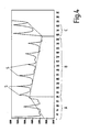
- Fig. 2 is a section of one associated pressure diagram
- Fig. 3 shows a partial sectional view of a the working cylinder in an embodiment according to the invention
- FIG a pressure diagram as it is with a working cylinder according to the invention 5 to 7 show other embodiments for the cylinder wall
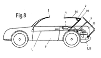
- Fig. 8 shows a schematic representation of a car with a folding top, at which the actuation arrangement according to the invention is provided.
- cylinders 1 to 4 are shown, for example for operating a vehicle roof or other mechanical systems can serve by their piston rods 5 with further actuators, Locking elements, levers or the like in a manner not shown in Connect.
- additional elements such as Limit switches, safety switches or the like may be provided.
- the cylinders 1 to 4 are via connections A1 to A4 and further via separate switching elements V1 to V4 with a common pressure circuit P (connections P1 to P4) or via separate throttles D1 to D4 with line T to tank 6 of the pressure fluid connected.
- spring-loaded and electrically operated Setbacks R1 to R4 are in the connection from the pressure circuit P to the switching elements V1 to V4 provided.
- the switching elements are setbacks and chokes, preferably also the pressure pump 8 together with filter 9 and Pressure relief valve 10 advantageously in a dash-dotted line in Fig. 1 indicated unit block 7 arranged.
- P 'and T' (the latter not mandatory) are designated There are outputs to an external control unit 11, via which Outputs the signal of a pressure sensor 12 switched on in the pressure circuit P. (Output P ') and advantageously a temperature sensor 13 (output T'), arranged here for example in the tank 6, passed to the control unit 11 be, which in a manner not shown with the electrical Actuators of the switching elements V1 to V4 is connected.
- the Control unit 11 is equipped with a preferably programmable computer, which shows the pressure curve and possibly the temperature (temperature-dependent Characteristic curve of the actuation arrangement) is monitored and evaluated and also controls the switching sequence of the switching elements V1 to V4.
- the basic pressure curve should now during a working cycle of a working cylinder 1 to 4 - still without Describing the improvements described in accordance with the present invention be in a known manner to recognize the end of the stroke or the end position can be used.
- the piston rods 5 of all working cylinders 1 to 4 retracted and the switching elements V1 up to V4 not energized.
- the pressure sensor 12 transmits the actual pressure curve in the pressure circuit P to the control unit 11, in the computer of which it is evaluated and with one of the Expiration ago known target pressure curve is compared.
- the control unit 11 in the computer of which it is evaluated and with one of the Expiration ago known target pressure curve is compared.
- the pressure builds up in the working cylinder 1 in a first phase (Increase A1 or A2) until the piston rod 5 begins to move, the The working cylinder extends and the pressure depends on the load as in section B1 or B2 (for a second, subsequently operated cylinder 2) runs.
- the pressure increases until it reaches the level specified via the pressure relief valve 10 Has reached C1 or C2.
- the controller 11 can use this pressure curve recognize the end position of the actuated cylinder. How through the curve (2) is indicated by the one pressure sensor 12 alone End position monitoring possible with successively actuated working cylinders.
- preferred embodiment is the cylinder tube 15 of the working cylinder 1 to 4 deformed by an indentation towards the central axis of the cylinder (at 16 and 17), preferably not only on one or more discrete places distributed along the circumference, but all around the whole Scope. If now the piston 14 in Fig.
- Fig. 4 shows a simple different embodiment of an inventive Working cylinder a section of the pressure diagram.
- the Cylinder wall is similar to FIG. 3 over the entire working stroke of the Equip the piston with deformations towards the inside at equal intervals, which are the sections with different cross-sectional areas form.
- section A there is an increasing system pressure as seen in section recognize that then in section B with slowly falling pressure on average transforms.
- Each time you pass through a section with the cross-sectional area of the cylinder-reducing deformation formation occurs a pressure peak S in the pressure circuit P.
- the computer can handle these pressure peaks count and thus provides relatively accurate information about each Position of the piston 14. If these pressure peaks S for each working cylinder still have special characteristics in the system, e.g. different relative heights of the peaks or the like, the control unit could it also recognizes the actuation of the respective cylinder.
- 5 to 7 are examples of other possible embodiments for sections with different cross-sectional areas in working cylinders shown. So instead of a bulge of the cylinder tube 15 after on the inside (as shown in FIG. 3) also an indentation 19 radially outwards be provided so that when passing through the corresponding section through the piston 14 whose piston seal 18 expands, the piston itself Moves faster in the short term and thus there is a pressure drop instead of one Pressure increase. Instead of the normal process pressure Such an embodiment delivers short-term pressure peaks Pressure drops, but just as well in the control unit 11 as signals can be used by the computer via the respective piston position can be counted or used in the same way as the pressure peaks of Fig. 4.
- a change in the pressure fluctuation pattern is in one embodiment possible, as shown by way of example in FIG. 7.
- the plugs 21, 22 are widely applicable and fixable.
- the plugs 21, 22 are preferably in Threaded bores can be screwed into the cylinder tube 15, with one in another embodiment of the invention set different configurations to let.
- the first four plugs 21 are like this screwed far in so that they protrude into the interior of the cylinder, Reduction of the cross-sectional area and thus when passing the piston 14 pressure peaks result.
- the last two plugs 22 in turn are a lot screwed further radially outwards, so leave recesses in the cylinder wall free and thus form cross-sectional area enlargements, which in Reductions in pressure result.
- Such a design of the working cylinder with adjustable or changeable cross-sectional area changes is particularly advantageous for test purposes or prototypes, where about still changes in coding, sequence of cylinder actuations (here without new programming of the control unit 11 possible) or fine-tuning for the absolute values or distances of the pressure fluctuations are necessary.
- the above-described device for effecting can a pressure modulation of the pressure in the pressure circuit of the actuation arrangement instead of between cylinder tube 15 and piston 14 or seal 18 also alternatively or additionally between the piston rod 5 and its through opening be provided in the working cylinder 1 to 4.
- the one previously described exemplary embodiment is also particularly for rodless cylinders with other variants for power take-off applicable.
- This additional element as a device for pressure modulation is on provided or connected to at least one component which at least another component moves past during the stroke of the working cylinder becomes.
- This is preferably the working cylinder, the piston or a any piston rod.
- It is advantageously structurally simple Embodiment of this variant, which is easy to manufacture and very operational sure there is at least one mechanical element present in at least a portion of the stroke of the piston in the working cylinder with at least one passed other mechanical element and / or a specially trained Area of one lying against and moving past the first mechanical element Surface interacts.
- Possible spring-loaded, moving parts in grooves, holes or similar structures of the moving component engage in the manner of a locking mechanism and thus affect the movement of the piston in the working cylinder.
- one of the relative to each other components being moved past be provided with a surface structure which, if the other component or the prestressed element this section runs over, the movement of the piston facilitates - by roughly the surface is smoother - or more difficult - if the surface is roughened - And thus accomplished the pressure modulation.
- the advantage of all of these Embodiments is that the effective for pressure modulation Structures designed independently of the hydraulically acting structures and can be designed.
- the spring preload is for a mechanical element in the manner of a friction brake on the piston or the piston rod to interact with differently rough sections on the Inner cylinder wall independent of the force with which the piston seal is pressed between its seat and the cylinder inner wall. Every component can thus be used in its optimal range without using simultaneous Doing multiple tasks of having to compromise.
- Fig. 8 is an exemplary application for the invention Actuating arrangement of the case of a vehicle top schematically shown.
- the frame parts of the soft top are labeled R1 and R2, and against each other or against the vehicle F by the working cylinders 1 and 2 movable.
- the top R1, R2 is under a cover flap K. protected, which can be operated via a third cylinder 3.
- the working cylinders 1 to 4 are in a common pressure circuit P, the one in the engine compartment Hydraulic unit 7 is connected, which again via an external control 11 is controlled in the manner already explained above.
- a limit switch E which is completely reached extended position of the convertible top and monitors this condition via the Signal line L reports to the controller 11.
- the actuating arrangement according to the invention is now in the vehicle top with the possibility of overlapping working cycles of the working cylinders particularly advantageous because it is the process of entering and Extending the roof despite still being very simple, inexpensive and Functionally reliable design of the actuating arrangement is accelerated considerably can be. It no longer has to be reached before actuating a cylinder wait for the end position of the previous cylinder, but movements that do not interfere with one another can overlap or even parallel respectively. For example, if the cylinder 3 is not yet complete, already very wide open cover flap K the two cylinders 1 and 2 can be controlled and the folding top begins. The cylinder 3 is in this case in a section through an inventive section part of his working stroke marked with cross-sectional changes.
- the closing process of the flap K can already be initiated and be started, even if the top is not yet fully closed, but the frame parts R1 and R2 are still en route to the end position the working cylinders 1 and 2 therefore in an intermediate position, the are also characterized by sections with cross-sectional changes - but still a large part of the space for the Have released pivoting movement of the flap K. Even an individual Identification of the individual cylinders 1 to 4 by characteristic sequences of sections with cross-sectional changes as facilities for achieving pressure modulation can be done so that the correct sequence the cylinder actuations can be monitored and not by one Fault in the system The folding top starts before the cover flap is open.
Description
Die Erfindung betrifft eine hydraulische Betätigungsanordnung für bewegliche Teile, insbesondere für verschwenkbare Klappen an Fahrzeugen, mit zumindest einem Arbeitszylinder mit einem an der Zylinderinnenwand dichtend anliegenden Kolben, einer mit dem oder jedem Arbeitszylinder verbundenen Steuereinheit und einem mit der Steuereinheit verbundenen Drucksensor in einem gemeinsamen Druckkreis, wobei die entsprechend entsprechend dem Druckverlauf im System veränderten Ausgangssignale des Drucksensors in der Steuereinheit zur Stellungskontrolle des oder jedes Arbeitszylinders dienen, sowie Fahrzeugverdecksystem mit einem vorzugsweise mehrteiligen Rahmenaufbau und einer allfälligen Abdeckklappe und zumindest einem Arbeitszylinder zur relativen Bewegung des Rahmenaufbaus und der Abdeckklappe gegenüber dem Fahrzeug bzw. zur relativen Bewegung dieser Teile gegeneinander, und Verfahren zur Stellungskontrolle und/oder Identifizierung eines Arbeitszylinders in einer hydraulischen Betätigungsanordnung für bewegliche Teile, insbesondere für verschwenkbare Klappen an Fahrzeugen, bei welchem der Druck im Druckkreis mit einem Drucksensor ermittelt und ein entsprechendes Signal einer Steuereinheit zur Auswertung zugeleitet wird.The invention relates to a hydraulic actuation arrangement for moving parts, in particular for pivotable flaps on vehicles, with at least one working cylinder with a piston sealingly against the cylinder inner wall, one with the or control unit connected to each working cylinder and one connected to the control unit Pressure sensor in a common pressure circuit, the corresponding accordingly the pressure curve in the system changed output signals of the pressure sensor in the control unit to control the position of the or each working cylinder, as well as the vehicle roof system with a preferably multi-part frame structure and a possible cover flap and at least one working cylinder for the relative movement of the frame structure and the cover flap relative to the vehicle or for the relative movement thereof Parts against each other, and methods for position control and / or identification of a working cylinder in a hydraulic actuation arrangement for moving parts, in particular for hinged flaps on vehicles, in which the pressure in the pressure circuit with determined a pressure sensor and a corresponding signal from a control unit for evaluation is forwarded.
Aus der AT-C-402 280 bzw. DE-A-1 96 29 065 ist eine hydraulische Betätigungsanordnung für ein Fahrzeugverdeck bekannt, bei der im gemeinsamen Druckkreis der Arbeitszylinder ein Drucksensor eingeschaltet ist, der mit einer Steuereinheit für die separaten Schaltelemente der Arbeitszylinder in Verbindung steht und dessen Ausgangssignal über der Zeit zusammen mit einer festen Schaltfolge der einzelnen Schaltelemente zur Endstellungskontrolle der einzelnen Arbeitszylinder dient. Damit kann zwar ohne aufwendige, separate Endlagenschalter an jedem Arbeitszylinder oder zugeordnetem Teil des Verdecksystems die Steuerung der Gesamtanordnung vereinfacht werden, wobei aber die Zylinder nur in einer vorgegebenen Reihenfolge geschaltet werden können und Änderungen der Schaltreihenfolge eine Neufassung des gesamten Steuerprogramms notwendig machen. Überdies ist keine Möglichkeit gegeben, Zwischenstellungen der Arbeitszylinder zu erkennen und so einfach zum Beispiel auch Überschneidungen in den Bewegungen bzw. mit externen Vorgängen vorsehen zu können.From AT-C-402 280 or DE-A-1 96 29 065 is a hydraulic actuation arrangement for a vehicle roof known, in which a pressure sensor in the common pressure circuit of the working cylinder is switched on, with a control unit for the separate switching elements of the working cylinders is connected and its output signal over time together with a fixed switching sequence of the individual switching elements for checking the end position of the individual Working cylinder serves. This can be done without expensive, separate limit switches control of the overall arrangement for each working cylinder or assigned part of the convertible top system be simplified, but the cylinders only in a predetermined order can be switched and changes in the switching order a new version of the entire tax program. Furthermore, there is no possibility Detect intermediate positions of the working cylinders and so easy, for example To be able to provide overlaps in the movements or with external processes.
Es ist daher die Aufgabe der vorliegenden Erfindung, eine hydraulische Betätigungsanordnung für prinzipiell beliebige Anwendungszwecke zu schaffen, die bei größtmöglicher Einfachheit die oben genannten Nachteile vermeidet und mit einer hinsichtlich Herstellung, Montage und Wartung kostengünstigen Bauweise eine flexibel programmierbare Steuerung sowie zeitsparende Überschneidungen oder parallel verlaufende Arbeitszyklen der Arbeitszylinder der Betätigungsanordnung ermöglicht. Weitere Aufgaben der Erfindung waren ein Fahrzeugverdecksystem, welches ebenfalls die soeben genannten Eigenschaften aufweist und ein mit einer einfachen, kostengünstigen und funktionssicheren Anlage durchführbares Verfahren zur Stellungskontrolle und/oder Identifizierung eines Arbeitszylinders in einer hydraulischen Betätigungsanordnung.It is therefore the object of the present invention to provide a hydraulic actuation arrangement to create for basically any application, with the greatest possible Simplicity avoids the disadvantages mentioned above and with a Assembly and maintenance of inexpensive construction a flexibly programmable control as well as time-saving overlaps or parallel working cycles of the working cylinders the actuation arrangement allows. Other objects of the invention were Vehicle roof system, which also has the properties just mentioned and one that can be carried out with a simple, inexpensive and functionally reliable system Method for checking the position and / or identification of a working cylinder in a hydraulic Operating arrangement.
Die erste Aufgabe wird erfindungsgemäß dadurch gelöst, daß Einrichtungen zum Bewirken einer Modulierung des Druckes im Arbeitszylinder vorhanden sind und die entsprechend der Druckmodulierung veränderten Ausgangssignale des Drucksensors der Steuereinheit zuleitbar sind und zur Stellungskontrolle und/oder Identifizierung des oder jedes Arbeitszylinders durch die Steuereinheit dienen. Die besagte Druckmodulierung überlagert sich dem allgemeinen abiaufgemäßen Druckverlauf des Systems und kann durch die Steuereinheit leicht identifiziert werden. Je nach Bedarf kann jeder beliebige Abschnitt im Verlauf des Arbeitshubs des Kolbens auf die beschriebene Weise gekennzeichnet werden, d.h. auch Positionen zwischen den Endstellungen, so daß ohne großen Aufwand für zusätzliche Stellungssensören eine Rückmeldung und nachfolgende Aktionen bereits bei Erreichen von Zwischenstellungen des Arbeitszylinders ermöglicht sind. Das macht aber auch die Herstellung und Montage der Betätigungsanordnung bei beliebigen Anwendungen kostengünstiger, einfacher und weniger fehleranfällig, da keinerlei separate Stellungssensoren und insgesamt weniger Bauteile, Kabel und Stecker montiert bzw. verlegt werden müssen. Die Steuereinheit kann mit weniger Eingängen des Auslangen finden und schließlich ist durch die ständige Druck-überwachung auch die Sicherheit bedeutend erhöht. Selbstverständlich kann die Druckmodulierung auch ein individualisierbares Signal für die Betätigung des jeweiligen Zylinders liefern.The first object is achieved in that devices for effecting a modulation of the pressure in the working cylinder are present and accordingly the pressure modulation changed output signals of the pressure sensor of the control unit are feedable and for position control and / or identification of the or each working cylinder serve by the control unit. The said pressure modulation is superimposed on this general course of pressure of the system and can be controlled by the control unit can be easily identified. Depending on your needs, any section in the course of the working stroke the piston in the manner described, i.e. positions too between the end positions, so that for additional position sensors without great effort feedback and subsequent actions as soon as intermediate positions are reached of the working cylinder are enabled. But that also makes the production and Assembly of the actuating arrangement for any application is cheaper, easier and less prone to errors because there are no separate position sensors and less overall Components, cables and plugs must be installed or laid. The control unit can Find with fewer inputs and finally through constant pressure monitoring security is also significantly increased. Of course, the pressure modulation also deliver an individualizable signal for the actuation of the respective cylinder.
Die oben genannten Vorteile werden noch vergrößert, wenn mehrere, über separate Schaltelemente ansteuerbare Arbeitszylinder im Druckkreis mit der (Fortsetzung auf Seite 3) Steuereinheit und dem Drucksensor vorgesehen sind. In diesem Fall können die aufeinanderfolgenden Arbeitszyklen der separaten Zylinder flexibler gestaltet werden und ein in der Arbeitsabfolge nachfolgend zu betätigender Arbeitszylinder schon wirksam werden, wenn der vorausgehende Arbeitszylinder noch in einer Zwischenstellung ist. Trotzdem bleibt die erfindungsgemäße Betätigungsanordnung baulich sehr einfach und kostengünstig und enthält weiterhin nur einen Drucksensor und eine Steuereinheit, die sehr einfach und wirtschaftlich ausgeführt sein können.The above benefits are magnified when multiple, over separate Switching elements controllable working cylinders in the pressure circuit with the (Continued on page 3) Control unit and the pressure sensor are provided. In this case, the successive working cycles of the separate cylinders made more flexible and a working cylinder to be actuated in the work sequence already take effect when the preceding cylinder is still in an intermediate position. Nevertheless, the actuation arrangement according to the invention remains structurally very simple and inexpensive and still only contains a pressure sensor and a control unit that is very simple and economical can be executed.
Zusätzlich oder alternativ zur Stellungskontrolle kann in Systemen mit mehreren Arbeitszylindern zur Ermöglichung von deren individualisierter Kennzeichnung vorgesehen sein, daß zumindest ein Arbeitszylinder mit Einrichtungen zur Druckmodulierung für eine diesen Arbeitszylinder aufgrund der speziellen Form der Druckmodulierung charakterisierenden Kennzeichnung ausgestattet ist. Durch dieses Merkmal ist eine individuelle Erkennung jedes einzelnen Arbeitszylinders oder jeder Gruppe von zugleich zu betätigenden Arbeitszylindern realisierbar, sodaß auch die sich überschneidende oder parallele Ansteuerung mehrerer Zylinder oder Zylindergruppen in einfacher Weise möglich ist. Die Kennzeichnung der einzelnen Zylinder kann durch die Größe und/oder das Vorzeichen der Druckveränderung erfolgen, wobei erstere Variante natürlich von der Auflösung des eingesetzten Drucksensors abhängt und sich auch allgemeine Druckschwankungen störend auswirken könnten. Bevorzugt ist daher eine Kennzeichnung in Art eines "Strichcodes", wobei der jeweilige Zylinder bzw. die jeweilige Zylindergruppe durch eine charakteristische Abfolge von Druckschwankungen (Abweichungen vom normalen Druckverlauf gemäß der jeweiligen Stellung des Kolbens) gekennzeichnet ist, unabhängig von deren absoluter Größe, allenfalls noch unter Einbeziehung des Vorzeichens der Druckänderung. Auch ist die Steuereinheit flexibler programmierbar, da, wenn es erwünscht ist, daß die Arbeitszylinder in anderer Reihenfolge angesteuert werden, nicht das gesamte Programm neu geschrieben werden muß, sondern nur die Codes für die Zylinderkennzeichnungen ausgetauscht werden müssen.In addition or as an alternative to position control, systems with several working cylinders to enable their individualized Labeling should be provided that at least one working cylinder with facilities for pressure modulation for one of these working cylinders due to the special form of characterization characterizing pressure modulation Is provided. This feature makes it possible to recognize each one individually individual working cylinder or each group of simultaneously operated Working cylinders realizable, so that the overlapping or parallel control of several cylinders or cylinder groups in simple Way is possible. The individual cylinders can be identified by the Size and / or the sign of the pressure change take place, the former Variant of course depends on the resolution of the pressure sensor used and general pressure fluctuations could also be disruptive. Prefers is therefore an identification in the form of a "barcode", the respective cylinder or the respective cylinder group by a characteristic Sequence of pressure fluctuations (deviations from the normal pressure curve according to the respective position of the piston) is marked independently of their absolute size, possibly including the sign the pressure change. The control unit is also more flexibly programmable, there if it is desired that the working cylinders in a different order can be controlled, the entire program can not be rewritten must, but only the codes for the cylinder identification exchanged Need to become.
Gemäß einer weiteren Ausführungsform der Erfindung sind die Einrichtungen zur Druckmodulierung durch zumindest einen Abschnitt mit einer gegenüber anderen Abschnitten betragsmäßig abweichenden Querschnittsfläche an zumindest einem von zwei während des Hubes des Kolbens aneinander vorbeibewegten und einander berührenden Teile des Arbeitszylinders gebildet. Diese Ausführung vermeidet zusätzliche Bauteile an den Arbeitszylindern und verringert somit den konstruktiven Aufwand, die Herstellung und Montage und auch die Funktionssicherheit aufgrund einer geringeren Anzahl störungsanfälliger Bauteile.According to another Embodiment of the invention are the facilities for Pressure modulation by at least one section with one against another Sections of different cross-sectional area on at least one of two moving past each other and each other during the stroke of the piston touching parts of the working cylinder. Avoids this execution additional components on the working cylinders and thus reduces the design Effort, manufacture and assembly and also functional reliability due to a smaller number of components prone to failure.
In einer ersten vorteilhaften Ausführungsform der Erfindung ist die Abweichung der Querschnittsfläche durch eine vorzugsweise über den gesamten Umfang des Zylinderrohres und/oder einer allfälligen Kolbenstange umlaufende Einbuchtung in diese Teile gegeben und der Kolben mit einer am Zylinderrohr anliegenden Dichtung bzw. die Durchführung der Kolbenstange mit einer an der Kolbenstange anliegenden Dichtung versehen ist. An der Stelle mit der abweichenden Querschnittsfläche, wobei es hier nur auf den absoluten Wert der Querschnittsfläche ankommt, wird sich die elastische Dichtung des Kolbens oder auch der Kolbenstange unter Beibehaltung ihrer Dichtwirkung ausdehnen und damit dem Kolben des Arbeitszylinders ein leichteres Verschieben ermöglicht. Resultierend aus dieser Querschnittsvergrößerung wird ein Druckabfall im Druckkreis auftreten, der ein entsprechendes Ausgangssignal des Drucksensors hervorruft, wenn der Kolben den Abschnitt mit der abweichenden Querschnittsfläche passiert. Der besagte kurzfristige Druckabfall ergibt also die durch die Steuereinheit verarbeitbare Druckmodulierung, durch welche das Passieren des Abschnittes des Zylinders mit der Querschnittserweiterung bzw. das Tätigwerden des Zylinders mit dieser Querschnittserweiterung erkennbar ist.In a first advantageous embodiment of the invention Deviation of the cross-sectional area by preferably over the entire Circumference of the cylinder tube and / or any piston rod Indentation in these parts and the piston with one on the cylinder barrel adjacent seal or the passage of the piston rod with one on the Piston rod adjacent seal is provided. At the point with the deviating Cross-sectional area, here it is only on the absolute value of the Arrives cross-sectional area, the elastic seal of the piston or expand the piston rod while maintaining its sealing effect and thus allows the piston of the working cylinder to move more easily. As a result of this increase in cross section, there is a drop in pressure occur in the pressure circuit, the corresponding output signal of the pressure sensor causes when the piston the section with the deviating Cross-sectional area happens. The said short-term pressure drop results in the pressure modulation that can be processed by the control unit, by means of which the Passing the section of the cylinder with the cross-sectional expansion or the action of the cylinder can be seen with this cross-sectional expansion is.
Gemäß einer speziellen Ausführungsform weist dabei die Einbuchtung in das Zylinderrohr in Richtung des Hubes des Kolbens eine Länge auf, die größer ist als die dichtend wirksame Länge des Kolbens. Dies bewirkt einen Strom des Druckfluids in den Raum hinter dem Kolben, der mit einem Druckabfall einhergeht. Durch den ausreichenden Volumenstrom wird der Kolben aber trotz des Druckabfalls weiterbewegt und gelangt schnell wieder in einen Abschnitt, in dem der Kolben wieder dicht abschließt und sich der Druck somit wieder auf den ablaufgemäßen Systemdruck einstellt. Der kurzfristige Druckabfall bei Passieren des Abschnittes mit der abweichenden Querschnittsfläche wirkt sich als dem ablaufgemäßen Druckverlauf aufgeprägte Modulierung aus und ist somit von der Steuereinheit erkennbar.According to a special embodiment, the indentation has in the cylinder tube in the direction of the stroke of the piston a length that is greater than the sealing effective length of the piston. This does one Flow of pressurized fluid into the space behind the piston with a drop in pressure accompanied. Due to the sufficient volume flow, the piston is moves on despite the pressure drop and quickly gets back into one Section in which the piston closes tightly again and the pressure thus sets back to the system pressure according to the process. The short-term pressure drop when passing the section with the different cross-sectional area has the effect of modulation impressed on the course of the pressure and can thus be recognized by the control unit.
Alternativ zu der oben beschriebenen Ausführungsform kann auch vorgesehen sein, daß die Abweichung der Querschnittsfläche durch eine vorzugsweise über den gesamten Umfang des Zylinderrohres und/oder einer allfälligen Kolbenstange umlaufende Ausbuchtung von diesen Teilen weg gegeben und der Kolben mit einer am Zylinderrohr anliegenden Dichtung bzw. die Durchführung der Kolbenstange mit einer an der Kolbenstange anliegenden Dichtung versehen ist. Unter sinngemäßer Umkehrung der oben erläuterten Vorgänge ereignet sich bei dieser, in der Herstellung meist einfacheren Ausführungsform ein kurzfristiger Druckanstieg, der sich als Druckspitze über dem ablaufgemäßen Druck im Druckkreis bemerkbar macht.As an alternative to the embodiment described above, provision can also be made be that the deviation of the cross-sectional area by a preferred over the entire circumference of the cylinder tube and / or any Piston rod circumferential bulge given away from these parts and the Piston with a seal against the cylinder tube or the bushing the piston rod with a seal that is in contact with the piston rod is. With the corresponding reversal of the processes explained above, occurs in this embodiment, which is usually simpler to manufacture, a short-term one Pressure rise, which is a pressure peak above the routine Pressure in the pressure circuit.
Eine wieder andere Ausführungsform gemäß der Erfindung ist dadurch gegeben, daß die Abweichung der Querschnittsfläche durch zumindest eine Bohrung im Zylinderrohr und/oder einer allfälligen Kolbenstange gegeben ist, in welche Bohrung allenfalls ein Stopfen verstellbar und fixierbar einsetzbar ist und daß der Kolben mit einer am Zylinderrohr anliegenden Dichtung bzw. die Durchführung der Kolbenstange mit einer an der Kolbenstange anliegenden Dichtung versehen ist. Die Größe der Veränderung der Querschnittsfläche des Arbeitszylinders ist durch Einsetzen oder Herausnehmen des Stopfens oder zum Beispiel durch ein unterschiedlich weites Hinein- oder Herausschrauben veränderlich und es kann sogar eine Umkehrung des Vorzeichens der Druckänderung bewerkstelligt werden, wenn etwa eine Schraube soweit in eine Bohrung in der Zylinderinnenwand hineingeschraubt wird, daß sie eine zuerst in den Zylinderinnenraum hin offene Ausnehmung schließt und schließlich vielleicht sogar die Innenwandung überragt und eine Querschnittsverengung bildet oder umgekehrt. Die besagte Bohrung könnte auch, speziell im Zylinderrohr, einer Auslaß- oder Bypassleitung zugeordnet sein, welche nach Passieren des Kolbens von diesem freigegeben wird, um kurzfristig Druckfluid aus dem Zylinder abzuleiten und derart einen kurzfristigen Druckabfall als Modulierung des ablaufgemäßen Drucks im Druckkreis hervorzurufen, der der Steuereinheit als Stellungssignal oder Erkennungssignal dieses Arbeitszylinders dient.Yet another embodiment according to the invention is thereby given that the deviation of the cross-sectional area by at least one There is a bore in the cylinder tube and / or a possible piston rod, In which hole a plug can be adjusted and fixed is and that the piston with a seal against the cylinder tube or the implementation of the piston rod with one against the piston rod Seal is provided. The size of the change in the cross-sectional area of the Working cylinder is by inserting or removing the plug or to Example by screwing in or out differently changeable and it can even reverse the sign of the pressure change be accomplished if, for example, a screw so far into a Bore is screwed into the cylinder inner wall so that it is one first in the cylinder interior open recess closes and finally perhaps even overhanging the inner wall and narrowing the cross-section forms or vice versa. The said bore could also, especially in the cylinder tube, be assigned to an outlet or bypass line, which after passing of the piston is released by this in order to temporarily release pressure fluid from the Derive cylinders and such a short-term pressure drop as modulation the process pressure in the pressure circuit, that of the control unit serves as a position signal or detection signal of this working cylinder.
Gemäß einer weiteren Ausführungsform der Erfindung ist vorgesehen, daß die Einrichtungen zur Druckmodulierung durch zumindest ein, von den Baueilen für den hydraulischen Betrieb der Arbeitszylinder separates Element, vorzugsweise am Arbeitszylinder, am Kolben oder der allfälligen Kolbenstange, gebildet sind. Damit wird die hydraulische Wirkung des Arbeitszylinders trotz er vorteilhaften Identifizierungs- und/oder Stellungskontrollmöglichkeit nicht oder nur unwesentlich beeinflußt.According to another Embodiment of the invention it is intended that the facilities for pressure modulation by at least one of the parts for the hydraulic operation of the working cylinder separate element, preferably on Working cylinder, on the piston or any piston rod, are formed. So that the hydraulic effect of the working cylinder is advantageous despite it Possibility of identification and / or position control not or only insignificantly influenced.
Vorzugsweise ist dabei das separate Element zur Druckmodulierung durch zumindest ein mechanisches Element gebildet, das in zumindest einem Abschnitt des Hubes des Kolbens im Arbeitszylinder mit zumindest einem vorbeibewegten anderen mechanischen Element und/oder einem speziell ausgebildeten Bereich einer am ersten mechanischen Element anliegenden und vorbeibewegten Fläche zusammenwirkt. Diese mechanische Ausführungsform ist baulich und herstellungsmäßig aufgrund ihrer Einfachheit sehr vorteilhaft und ist auch im Betrieb funktionssicher.The separate element for pressure modulation is preferably through at least one mechanical element formed in at least one section the stroke of the piston in the working cylinder with at least one moved past other mechanical element and / or a specially trained area a surface lying against and moving past the first mechanical element interacts. This mechanical embodiment is structural and manufacturing very advantageous due to its simplicity and is also in Operation reliable.
Um eine einfach und mit bewährten herkömmlichen Bauelementen leicht herzustellende mechanische Ausführungsform zu realisieren, ist vorgesehen, daß das separate Element zumindest ein gegen das vorbeibewegte Element oder die vorbeibewegte Fläche vorgespanntes Bauteil ist, das in zumindest einem Abschnitt des Hubes des Kolbens mit zumindest einer betragsmäßig abweichenden Querschnittsfläche und/oder einer die Relativbewegung beeinflussenden Oberflächenstruktur zusammenwirkt, derart die Kolbenbewegung erleichtert oder erschwert und somit die Druckmodulierung bewerkstelligt.To make a simple and easy to manufacture with proven conventional components to implement mechanical embodiment, it is provided that the separate element at least one against the moving element or the moving surface is prestressed component, which in at least one Section of the stroke of the piston with at least one different amount Cross-sectional area and / or a surface structure influencing the relative movement interacts, so the piston movement facilitated or difficult and thus accomplished the pressure modulation.
Zur einfachen Überwachung der Kolbenposition und zur Ermittlung von Zwischenstellungen ist eine vorteilhafte Ausführungsform dadurch gekennzeichnet, daß die Zylinderwandung und/oder eine allfällige Kolbenstange über ihre Länge in regelmäßigen Abständen mit den Einrichtungen zur Druckmodulierung versehen ist. Damit kann durch einen einfach zu realisierenden Zähler in der Steuereinheit die Kolbenstellung durch Mitzählen der aufgetretenden Druckschwankungen ermittelt und für die weitere Schaltabfolge berücksichtigt werden. Ein Zähler kann in der Steuereinheit, falls er nicht schon vorhanden sein sollte, in einfacher Weise realisiert werden. Wenn allenfalls noch die einzelnen Druckschwankungen "codiert" sind, durch den Absolutwert, eine zeitlich definierte Abfolge von Schwankungen od. dgl. können in sehr genauer Weise für jeden im System befindlichen Arbeitszylinder End- und Zwischenstellungen mit nur einem Drucksensor ermittelt und für die Weiterverarbeitung in der Steuereinheit bereitgestellt werden.For easy monitoring of the piston position and for determining An advantageous embodiment is characterized by intermediate positions, that the cylinder wall and / or a possible piston rod on their Length at regular intervals with the devices for pressure modulation is provided. This can be done by an easy to implement counter in the Control unit the piston position by counting the pressure fluctuations that occur determined and taken into account for the further switching sequence become. A counter can be in the control unit if it does not already exist should be realized in a simple way. If only that individual pressure fluctuations are "coded" by the absolute value Time-defined sequence of fluctuations or the like can be done in a very precise manner End and intermediate positions for each working cylinder in the system determined with only one pressure sensor and for further processing in be provided to the control unit.
In einer bevorzugten Ausführungsform der Erfindung ist vorgesehen, daß zur Überwachung und Auswertung des Druckverlaufes in der Steuereinheit ein Rechner vorgesehen ist, der allenfalls auch die Schaltfolgen der Schaltelemente bei mehreren Arbeitszylindern steuert. Damit kann die Überwachung des Druckverlaufes, die allfällige Identifizierung der Arbeitszylinder und die Umsetzung der Drucksignale in eine Auslösung von Schaltfolgen sehr einfach vorgenommen werden, wobei auch Änderungen zur Anpassung an geänderte Gegebenheiten leicht möglich sind.In a preferred embodiment of the invention it is provided that to monitor and evaluate the pressure curve in the control unit Computer is provided, which at most also the switching sequences of the switching elements controls with several working cylinders. This allows the monitoring of the Pressure history, the possible identification of the working cylinder and the Converting the pressure signals into triggering switching sequences is very simple be made, including changes to adapt to changed circumstances are easily possible.
Besonders vorteilhaft ist weiters eine Ausführungsform der Betätigungsanordnung, bei der vorgesehen ist, daß zumindest ein Temperatursensor, vorzugsweise am oder zumindest in der Nähe des Druckkreises, vorgesehen ist, der ebenfalls mit der Steuereinheit in Verbindung steht und über den die Temperaturabhängigkeit der Betätigungsanordnung berücksichtigbar ist. Da die Zeitdauer der Verstellung des jeweiligen Arbeitszylinders zwischen den unterschiedlichen End- bzw. Zwischenstellungen vom hydraulischen Volumenstrom abhängt und dieser von der Temperatur, kann auf diese Weise eine einfache Kompensation vorgenommen und können zwei voneinander unabhängige Parameter erhalten werden, mit denen die Steuerung des Betätigungsablaufes sicher durchgeführt werden kann.An embodiment of the actuation arrangement is also particularly advantageous, in which it is provided that at least one temperature sensor, is preferably provided on or at least in the vicinity of the pressure circuit, which is also connected to the control unit and via which the Temperature dependence of the actuation arrangement can be taken into account. Since the Duration of the adjustment of the respective working cylinder between the different end or intermediate positions of the hydraulic volume flow depends and this on the temperature, can be an easy this way Compensation made and can be two independent parameters can be obtained with which the control of the actuation process is safe can be carried out.
Die zweite Aufgabe wird durch ein erfindungsgemäßes Fahrzeugverdecksystem mit einem vorzugsweise mehrteiligen Rahmenaufbau und einer allfälligen Abdeckklappe und zumindest einem Arbeitszylinder zur relativen Bewegung des Rahmenaufbaus und allenfalls der Abdeckklappe gegenüber dem Fahrzeug bzw. zur relativen Bewegung dieser Teile gegeneinander, gelöst, welche dadurch gekennzeichnet ist, daß der zumindest eine Arbeitszylinder Teil einer Betätigungsanordnung nach einem der vorhergehenden Absätze ist. Alle der genannte Vorteile treffen auch bei der Anwendung der Betätigungsanordnung zum Aus- und Einfahren eines Fahrzeugverdecks zu, bei dem die Möglichkeit der Überschneidung von Arbeitszyklen verschiedener Arbeitszylinder einen rascheren Ablauf des Aus- und Einfahrens mit einer sehr einfachen, wirtschaftlichen und funktionssicheren Anordnung ermöglicht. Darüberhinaus ist eine genauere Überwachung des Vorganges gewährleistet und eventuell auftretende Fehlfunktionen können schneller diagnostiziert und behoben werden, da auch wichtige Zwischenstellungen der Arbeitszylinder in die Systemüberwachung miteinbezogen sind.The second object is achieved by a vehicle top system according to the invention with a preferably multi-part frame structure and any Cover flap and at least one working cylinder for the relative movement of the Frame structure and possibly the cover flap opposite the vehicle or relative movement of these parts against each other, solved, which is characterized is that the at least one working cylinder is part of an actuation arrangement according to one of the preceding paragraphs. All of the mentioned advantages also apply when using the actuation arrangement Extending and retracting a vehicle roof with the possibility of Overlap of working cycles of different working cylinders faster expiration and retraction with a very simple, economical and reliable arrangement. Beyond that ensures a more precise monitoring of the process and any occurring Malfunctions can be diagnosed and remedied more quickly, there are also important intermediate positions of the working cylinders in the system monitoring are involved.
Selbstverständlich können in allen der oben genannten Fälle allenfalls zusätzlich und bedarfsweise Sicherheitsschalter, Endschalter od. dgl. vorgesehen sein, die den jeweiligen Vorgang zusätzlich oder separat überwachen.Of course, in all of the above cases at best In addition and if necessary, safety switches, limit switches or the like are provided be who monitor the respective process additionally or separately.
Zur Lösung der erfindungsgemäßen Aufgabenstellung ist auch ein Verfahren zur Stellungskontrolle und/oder Identifizierung eines Arbeitszylinders in einer hydraulischen Betätigungsanordnung vorgesehen, bei welchem der Druck im Druckkreis mit einem Drucksensor ermittelt und ein entsprechendes Signal einer Steuereinheit zur Auswertung zugeleitet wird, und welches dadurch gekennzeichnet ist, daß der Druck im Druckkreis bei Passieren eines vorbesimmten Abschnittes entlang des Hubes des Kolbens in einer diese Stellung und/oder den jeweiligen Zylinder charakterisierenden Weise moduliert wird, daß ein dieser Druckmodulation entsprechendes Signal erzeugt und der Steuereinheit der Betätigungsanordnung zur Auswertung zugeleitet wird.There is also a method for solving the task according to the invention for position control and / or identification of a working cylinder in a hydraulic actuation arrangement is provided, in which the pressure in Pressure circuit determined with a pressure sensor and a corresponding signal is fed to a control unit for evaluation, and which thereby is characterized in that the pressure in the pressure circuit when a predetermined one passes Section along the stroke of the piston in this position and / or modulating the characterizing cylinder, that generates a signal corresponding to this pressure modulation and the control unit the actuation arrangement is fed for evaluation.
In einer vorteilhaften Ausführungsform ist weiters vorgesehen, daß der Druck im Druckkreis bei Passieren des vorbestimmten Abschnittes durch Veränderung des Widerstandes der Kolbenbewegung moduliert wird.In an advantageous embodiment it is further provided that the Pressure in the pressure circuit when passing through the predetermined section by changing the resistance of the piston movement is modulated.
Eine alternative Ausführungsform sieht vor, daß der Druck im Druckkreis bei Passieren des vorbestimmten Abschnittes durch Ableiten eines Teils des Druckfluids, vorzugsweise ein zumindest kurzfristiges Verbinden der Räume vor und hinter dem Kolben, moduliert wird.An alternative embodiment provides that the pressure in the pressure circuit when passing the predetermined section by deriving part of the Pressure fluids, preferably an at least short-term connection of the rooms and behind the piston, is modulated.
Die Erfindung wird zusammen mit weiteren Merkmalen und Vorteilen im
folgenden und anhand der beigefügten Zeichnungen noch näher erläutert. Dabei
zeigt Fig. 1 ein schematisches Schaltschema einer hydraulischen Betätigungsanordnung
mit vier Arbeitszylindern, Fig. 2 ist ein Ausschnitt aus einem
zugehörigen Druckdiagramm, Fig. 3 zeigt eine teilweise Schnittansicht eines
der Arbeitszylinder in einer erfindungsgemäßen Ausführungsform, Fig. zeigt
ein Druckdiagramm, wie es sich mit einem erfindungsgemäßen Arbeitszylinder
ergibt, Fig. 5 bis 7 zeigen andere Ausführungsformen für die Zylinderwandung
und Fig. 8 zeigt in schematischer Darstellung ein Auto mit Faltverdeck, bei
dem die erfindungsgemäße Betätigungsanordnung vorgesehen ist.The invention, along with other features and advantages, are described in
following and explained in more detail with reference to the accompanying drawings. there
1 shows a schematic circuit diagram of a hydraulic actuation arrangement
with four working cylinders, Fig. 2 is a section of one
associated pressure diagram, Fig. 3 shows a partial sectional view of a
the working cylinder in an embodiment according to the invention, FIG
a pressure diagram as it is with a working cylinder according to the
In Fig. 1 sind vier Arbeitszylinder 1 bis 4 dargestellt, die beispielsweise
zur Betätigung eines Fahrzeugverdecks oder anderer mechanischer Systeme
dienen können, indem deren Kolbenstangen 5 mit weiteren Betätigungselementen,
Sperrelementen, Hebeln od. dgl. auf nicht näher dargestellte Weise in
Verbindung stehen. Selbstverständlich können auch zusätzliche Elemente wie
Endschalter, Sicherheitsschalter od. dgl. vorgesehen sein. Die Zylinder 1 bis
4 sind über Anschlüsse A1 bis A4 und weiter über separate Schaltelemente V1
bis V4 mit einem gemeinsamen Druckkreis P (Anschlüsse P1 bis P4) bzw. über
separate Drosseln D1 bis D4 mit der Leitung T zum Tank 6 des Druckfluids
verbunden. Auch beispielsweise federbelastete und elektrisch betätigte
Rückschläge R1 bis R4 sind in der Verbindung vom Druckkreis P zu den Schaltelementen
V1 bis V4 vorgesehen. Dabei sind die Schaltelemente, Rückschläge
und Drosseln, vorzugsweise auch noch die Druckpumpe 8 samt Filter 9 sowie
Druckbegrenzungsventil 10 vorteilhafterweise in einem in Fig. 1 strichpunktiert
angedeuteten Aggregatblock 7 angeordnet.In Fig. 1, four working
Am Aggregatblock 7 sind mit P' und T' (letzterer nicht zwingend) bezeichnete
Ausgänge zu einer externen Steuereinheit 11 vorhanden, über welche
Ausgänge das Signal eines im Druckkreis P eingeschalteten Drucksensors 12
(Ausgang P') und vorteilhafterweise eines Temperatursensors 13 (Ausgang T'),
hier beispielsweise im Tank 6 angeordnet, zur Steuereinheit 11 geleitet
werden, welche auf nicht näher dargestellte Weise mit den elektrischen
Betätigungselementen der Schaltelemente V1 bis V4 in Verbindung steht. Die
Steuereinheit 11 ist mit einem vorzugsweise programmierbaren Rechner ausgerüstet,
der den Druckverlauf und allenfalls die Temperatur (temperaturabhängige
Kennlinie der Betätigungsanordnung) überwacht und auswertet und auch
die Schaltfolge der Schaltelemente V1 bis V4 steuert.On the
Unter Bezugnahme auf Fig. 2 soll nun der prinzipielle Druckverlauf
während eines Arbeitszyklus eines Arbeitszylinders 1 bis 4 - noch ohne
Berücksichtigung der Verbesserungen gemäß der vorliegenden Erfindungbeschrieben
werden, der in bekannter Weise bereits zum Erkennen des Hubendes
bzw. der Endposition herangezogen werden kann. Zu Beginn sind die Kolbenstangen
5 aller Arbeitszylinder 1 bis 4 eingefahren und die Schaltelemente V1
bis V4 nicht bestromt. Es wird nun der Aggregatblock 7 bzw. dessen Druckpumpe
8 eingeschaltet und das Schaltelement V1 betätigt, worauf der Arbeitszylinder
1 ausfährt. Der Drucksensor 12 übermittelt den Ist-Druckverlauf im Druckkreis
P an die Steuereinheit 11, in deren Rechner er ausgewertet und mit einem vom
Ablauf her bekannten Soll-Druckverlauf verglichen wird. Wie in Fig. 2 zu
sehen ist, baut sich der Druck im Arbeitszylinder 1 in einer ersten Phase auf
(Anstieg A1 bzw. A2), bis sich die Kolbenstange 5 zu bewegen beginnt, der
Arbeitszylinder ausfährt und der Druck je nach Belastung wie im Abschnitt B1
oder B2 (für einen zweiten, nachfolgend betätigten Arbeitszylinder 2) verläuft.
Bei Erreichen der Endstellung bzw. des Hubendes steigt der Druck
soweit an, bis er das über das Druckbegrenzungsventil 10 vorgegebene Niveau
C1 bzw. C2 erreicht hat. Die Steuerung 11 kann anhand dieses Druckverlaufes
die Endstellung des jeweils betätigten Arbeitszylinders erkennen. Wie durch
die Kurve (2) angedeutet, ist allein durch den einen Drucksensor 12 eine
Endstellungsüberwachung bei nacheinander betätigten Arbeitszylindern möglich.With reference to Fig. 2, the basic pressure curve should now
during a working cycle of a working
Gemäß einer beispielhaften Ausführungsform der Erfindung sind nun
bestimmte oder alle Arbeitszylinder 1 bis 4 entlang des vom Kolben 14 während
seines Arbeitshubs durchlaufenen Weges derart ausgebildet, daß zumindest ein
Abschnitt mit einer gegenüber anderen Abschnitten abweichenden
Querschnittsfläche vorgesehen ist. In der in Fig. 3 dargestellten ersten
bevorzugten Ausführungsform ist dazu das Zylinderrohr 15 des Arbeitszylinders
1 bis 4 durch eine Einbuchtung auf die Mittelachse des Zylinders hin verformt
(bei 16 und 17), vorzugsweise nicht nur an einer oder mehreren diskret
entlang des Umfangs verteilten Stellen, sondern umlaufend über den gesamten
Umfang. Wenn sich nun der Kolben 14 in Fig. 3 unter dem Einfluß des Hydraulikfluid
in Pfeilrichtung bewegt, wird seine Kolbendichtung 18 bei
Erreichen des ersten ausgebuchteten Abschnittes (bei 16) mit unterschiedlicher
Querschnittsfläche plastisch verformt und der Kolben 14 etwas gebremst,
was zu einem Druckanstieg führt, der den Kolben 14 schließlich über die Verformung
hinweg und am Abschnitt 16 vorbeidrückt, wonach der Druck dann wieder
auf das ablaufgemäße Niveau absinkt. Die Verformung der Dichtung 18 geht
wieder zurück und die Bewegung des Kolbens 14 erfolgt wieder entsprechend dem
ablaufgemäßen Druck im Arbeitszylinder. Das Durchlaufen des Abschnittes 16
mit der Verformung des Zylinderrohres 15 macht sich also in einem kurzen
Druckanstieg, einer Druckspitze, bemerkbar, welche über den Drucksensor 12
auch der Steuerung 11 mitgeteilt wird und als Signal für das Erreichen der
jeweiligen Stellung durch den Kolben dienen kann. Der gleiche Vorgang wiederholt
sich beim Beispiel der Fig. 3 auch im zweiten Abschnitt mit gegenüber
dem Standardquerschnitt abweichendem Querschnitt des Arbeitszylinders (mit
dem verformten Abschnitt 17) und zeigt dann der Steuerung 11 an, daß der
Kolben 14 diesen zweiten Abschnitt erreicht bzw. durchlaufen hat. Auf diese
Weise kann also durch die Schaffung von Abschnitten im Arbeitszylinder, die
gegenüber der normalen Querschnittsfläche eine unterschiedliche Querschnittsfläche
aufweisen, eine charakteristische Druckmodulierung im Druckkreis P
hervorgerufen werden und können die korrespondierenden Ausgangssignale des
Drucksensors 12 zur Stellungskontrolle des jeweiligen Arbeitszylinders 1 bis
4 dienen.According to an exemplary embodiment of the invention
certain or all of the working
Wenn einzelne Arbeitszylinder eine sich von allen anderen Arbeitszylindern
unterscheidende Abfolge von Abschnitten mit abweichender Querschnittsfläche
aufweisen, ähnlich einem "Strichcode", ist damit eine sichere
Identifizierung des jeweiligen Arbeitszylinders und beispielsweise durch die
Steuereinheit 11 eine Kontrolle möglich, ob auch der ablaufgemäß vorgesehene
Zylinder tatsächlich die jeweilige Position passiert hat. Selbstverständlich
können die beiden beschriebenen Varianten auch in Kombination vorgesehen
werden, sodaß entlang des Arbeitshubs der Kolben aller Zylinder Abschnitte
mit unterschiedlicher Querschnittsfläche vorgesehen sind, die alle für den
Ablauf des Gesamtsystems wichtigen Zwischenstellungen kennzeichnen und wobei
alle Abschnitte jedes einzelnen Zylinders mit einer diesen Zylinder eindeutig
charakterisierenden Abfolge von Verformungen innerhalb jedes derartigen
Abschnitts versehen sind.If individual working cylinders are different from all other working cylinders
distinctive sequence of sections with different cross-sectional area
have, similar to a "bar code", is thus a safe
Identification of the respective working cylinder and, for example, by the
Fig. 4 zeigt für eine einfache andere Ausführungsform eines erfindungsgemäßen
Arbeitszylinders einen Ausschnitt aus dem Druckdiagramm. Die
Zylinderwandung ist dabei ähnlich der Fig. 3 über den gesamten Arbeitshub des
Kolbens in gleichen Abständen mit Verformungen nach innen hin versehen,
welche die Abschnitte mit betragsmäßig abweichender Querschnittsfläche
bilden. Im Abschnitt A ist ein im Schnitt gesehen ansteigender Systemdruck zu
erkennen, der dann in den Abschnitt B mit langsam im Mittel sinkenden Druck
übergeht. Bei jedem Durchlaufen eines Abschnittes mit der die Querschnittsfläche
des Zylinders vermindernden Verformung kommt es zur Ausbildung
einer Druckspitze S im Druckkreis P. Ein in der Steuereinheit vorgesehener
Rechner kann gemäß einer weiteren Ausführungsvariante diese Druckspitzen
mitzählen und liefert derart eine relativ genaue Information über die jeweilige
Stellung des Kolbens 14. Wenn diese Druckspitzen S für jeden Arbeitszylinder
im System noch spezielle Charakteristika aufweisen, etwa
unterschiedliche relative Höhen der Spitzen od. dgl., könnte die Steuereinheit
daran auch noch die Betätigung des jeweiligen Zylinders erkennen.Fig. 4 shows a simple different embodiment of an inventive
Working cylinder a section of the pressure diagram. The
Cylinder wall is similar to FIG. 3 over the entire working stroke of the
Equip the piston with deformations towards the inside at equal intervals,
which are the sections with different cross-sectional areas
form. In section A there is an increasing system pressure as seen in section
recognize that then in section B with slowly falling pressure on average
transforms. Each time you pass through a section with the cross-sectional area
of the cylinder-reducing deformation, formation occurs
a pressure peak S in the pressure circuit P. A provided in the control unit
According to a further embodiment variant, the computer can handle these pressure peaks
count and thus provides relatively accurate information about each
Position of the
In den Fig. 5 bis 7 sind beispielhaft andere mögliche Ausführungsformen
für Abschnitte mit unterschiedlicher Querschnittsfläche in Arbeitszylindern
dargestellt. So kann anstelle einer Ausbuchtung des Zylinderrohres 15 nach
innen hin (wie in Fig. 3 gezeigt) auch eine Einbuchtung 19 radial nach außen
hin vorgesehen sein, sodaß sich beim Durchlaufen des entsprechenden Abschnittes
durch den Kolben 14 dessen Kolbendichtung 18 ausdehnt, der Kolben sich
kurzfristig schneller bewegt und sich somit ein Druckabfall anstelle eines
Druckanstiegs einstellt. Anstelle von über den normalen ablaufgemäßen Druck
hinausgehenden Druckspitzen liefert eine derartige Ausführungsform kurzfristige
Druckeinbrüche, die aber genausogut in der Steuereinheit 11 als Signale
über die jeweilige Kolbenstellung herangezogen werden können, vom Rechner
mitgezählt bzw. auf die gleiche Weise verwertet werden können wie die Druckspitzen
der Fig. 4. Eine noch größere Flexibilität und viel mehr Möglichkeiten
zur Codierung von Positionen oder separaten Arbeitszylindern ist bei der
in Fig. 6 dargestellten Ausführungsform der Zylinderwandung 15 gegeben, bei
der eine Kombination von ausgebuchteten Abschnitten 16, 17 und 20 des Zylinderrohres
15 radial nach innen und Abschnitten 19 mit Einbuchtungen radial
nach außen hin vorgesehen ist. Bei Durchlaufen des Abschnittes D mit seinen
beiden vorgewölbten Abschnitten 16, 17, dem nachfolgenden eingebuchteten
Abschnitt 19 und dem abschließenden wieder vorgewölbten Abschnitt 20 ergibt
sich im Druckkreis P ein für diesen Abschnitt D und/oder den jeweiligen
Zylinder ganz charakteristisches Druckschwankungsmuster, welches der Steuerung
signalisiert, daß der Kolben 14 des gerade aktiven Zylinders gerade
diesen Abschnitt D durchlaufen hat bzw. daß der Kolben 14 des durch dieses
Druckschwankungsmuster gekennzeichneten Zylinders gerade seine für den
weiteren Gesamtablauf wichtige Zwischenstellung durchlaufen hat.5 to 7 are examples of other possible embodiments
for sections with different cross-sectional areas in working cylinders
shown. So instead of a bulge of the
Eine Veränderung des Druckschwankungsmusters ist bei einer Ausführungsform
möglich, wie sie beispielhaft in Fig. 7 gezeigt ist. Hier sind in der
Zylinderwand 15 Bohrungen vorhanden, in die Stopfen 21, 22 unterschiedlich
weit einsetzbar und fixierbar sind. Vorzugsweise sind die Stopfen 21, 22 in
Gewindebohrungen im Zylinderrohr 15 einschraubbar, wobei sich in einer
weiteren Ausgestaltung der Erfindung unterschiedliche Konfigurationen einstellen
lassen. So sind im Beispiel der Fig. 7 die ersten vier Stopfen 21 so
weit hineingeschraubt, daß sie in das Innere des Zylinders hineinragen,
Verkleinerungen der Querschnittsfläche und damit beim Passieren des Kolbens
14 Druckspitzen ergeben. Die beiden letzten Stopfen 22 wiederum sind viel
weiter radial nach außen geschraubt, lassen also Ausnehmungen in der Zylinderwand
frei und bilden somit Querschnittflächenvergrößerungen, die in
Druckverminderungen resultieren. Eine derartige Ausführung der Arbeitszylinder
mit einstellbaren oder veränderlichen Querschnittsflächenveränderungen
ist besonders vorteilhaft für Testzwecke oder Prototypen, bei denen etwa noch
öfter Änderungen der Codierungen, Abfolge der Zylinderbetätigungen (hier ohne
neue Programmierung der Steuereinheit 11 möglich) oder Feinabstimmungen für
die absoluten Werte oder Abstände der Druckschwankungen notwendig sind.A change in the pressure fluctuation pattern is in one embodiment
possible, as shown by way of example in FIG. 7. Here are in the
Selbstverständlich können die oben beschriebenen Einrichtung zum Bewirken
einer Druckmodulierung des Drucks im Druckkreis der Betätigungsanordnung
anstelle zwischen Zylinderrohr 15 und Kolben 14 bzw. Dichtung 18 auch
alternativ oder zusätzlich zwischen der Kolbenstange 5 und deren Durchführungsöffnung
im Arbeitszylinder 1 bis 4 vorgesehen sein. Die zuvor beschriebene
beispielhafte Ausführungsform ist dagegen auch besonders für
kolbenstangenlose Arbeitszylinder mit anderen Varianten für den Kraftabgriff
anwendbar.Of course, the above-described device for effecting can
a pressure modulation of the pressure in the pressure circuit of the actuation arrangement
instead of between
Die bisher beschriebenen Ausführungsformen benutzen alle ausschließlich bereits für den hydraulischen Betrieb des Arbeitszylinders notwendige Bauelemente, um die identifizierende bzw. stellungsanzeigende Druckmodulierung zu erzeugen. Es ist aber in vielen Fällen vorteilhaft, den hydraulischen Betrieb des Arbeitszylinders sowenig wie möglich zu beeinflussen, d.h. beispielsweise die Dichtung des Kolbens oder der Kolbenstange sowenig wie möglich mechanischen Belastungen durch Verformung oder Überfahren von Ausnehmungen oder Ausbuchtungen auszusetzen. Daher sind in diesem Fall Ausführungsformen der Erfindung vorteilhaft, die zumindest ein separates Element zur Erzeugung der Druckmodulierung verwenden, das zusätzlich zu den eigentlich hydraulischen wirkenden Elementen wie Kolben, Dichtung od. dgl. vorhanden ist.The embodiments described so far all use exclusively Components already required for the hydraulic operation of the working cylinder, around the identifying or position-indicating pressure modulation to create. In many cases, however, it is advantageous to use the hydraulic one Influence the operation of the working cylinder as little as possible, i.e. for example, the seal of the piston or the piston rod as little as possible mechanical loads due to deformation or driving over recesses or suspend bulges. Therefore, in this case, there are embodiments advantageous of the invention, the at least one separate element to create the pressure modulation, in addition to the actually hydraulic acting elements such as pistons, seals or the like is.
Dieses zusätzliche Element als Einrichtung zur Druckmodulierung ist an zumindest einem Bauteil vorgesehen oder damit verbunden, der an zumindest einem anderen Bauteil während des Hubes des Arbeitszylinders vorbeibewegt wird. Vorzugsweise wird dies der Arbeitszylinder, der Kolben oder eine allfällige Kolbenstange sein. Vorteilhafterweise ist als baulich einfache Ausführungsform dieser Variante, die einfach herzustellen und im Betrieb sehr sicher ist, zumindest ein mechanisches Element vorhanden, das in zumindest einem Abschnitt des Hubes des Kolbens im Arbeitszylinder mit zumindest einem vorbeibewegten anderen mechanischen Element und/oder einem speziell ausgebildeten Bereich einer am ersten mechanischen Element anliegenden und vorbeibewegten Fläche zusammenwirkt. Denkbar sind etwa federbelastet vorgespannte, bewegliche Teile, die in Nuten, Bohrungen oder ähnliche Strukturen des vorbeibewegten Bauteils in Art eines Rastmechanismus eingreifen und derart die Bewegung des Kolbens im Arbeitszylinders beeinflussen. Genausogut kann aber alternativ dazu oder zusätzlich einer der relativ aneinander vorbeibewegten Bauteile mit einer Oberflächenstruktur versehen sein, die, wenn der andere Bauteil bzw. das vorgespannte Element diesen Abschnitt überfährt, die Bewegung des Kolbens erleichtert - indem die Oberfläche etwa glatter geschliffen ist - oder erschwert - wenn die Oberfläche aufgerauht ist - und somit die Druckmodulierung bewerkstelligt. Der Vorteil aller dieser Ausführungsformen liegt darin, daß die für die Druckmodulierung wirksamen Strukturen unabhängig von den hydraulisch wirkenden Strukturen ausgelegt und gestaltet sein können. So ist beispielsweise die Federvorspannung für ein mechanisches Element in der Art einer Reibbremse am Kolben oder der Kolbenstange zum Zusammenwirken mit unterschiedlich rauhen Abschnitten an der Zylinderinnenwandung unabhängig von der Kraft, mit der die Kolbendichtung zwischen ihrem Sitz und der Zylinderinnenwandung gepreßt wird. Jeder Bauteil kann somit in seinem optimalen Bereich eingesetzt werden, ohne durch gleichzeitiges Erfüllen mehrerer Aufgaben Kompromisse eingehen zu müssen.This additional element as a device for pressure modulation is on provided or connected to at least one component which at least another component moves past during the stroke of the working cylinder becomes. This is preferably the working cylinder, the piston or a any piston rod. It is advantageously structurally simple Embodiment of this variant, which is easy to manufacture and very operational sure there is at least one mechanical element present in at least a portion of the stroke of the piston in the working cylinder with at least one passed other mechanical element and / or a specially trained Area of one lying against and moving past the first mechanical element Surface interacts. Possible spring-loaded, moving parts in grooves, holes or similar structures of the moving component engage in the manner of a locking mechanism and thus affect the movement of the piston in the working cylinder. As good as can alternatively or additionally one of the relative to each other components being moved past be provided with a surface structure which, if the other component or the prestressed element this section runs over, the movement of the piston facilitates - by roughly the surface is smoother - or more difficult - if the surface is roughened - And thus accomplished the pressure modulation. The advantage of all of these Embodiments is that the effective for pressure modulation Structures designed independently of the hydraulically acting structures and can be designed. For example, the spring preload is for a mechanical element in the manner of a friction brake on the piston or the piston rod to interact with differently rough sections on the Inner cylinder wall independent of the force with which the piston seal is pressed between its seat and the cylinder inner wall. Every component can thus be used in its optimal range without using simultaneous Doing multiple tasks of having to compromise.
In Fig. 8 ist als ein beispielhafter Anwendungsfall für die erfindungsgemäße
Betätigungsanordnung der Fall eines Fahrzeugverdecks schematisch
dargestellt. Die Rahmenteile des Verdecks sind mit R1 und R2 bezeichnet, und
gegeneinander bzw. gegenüber dem Fahrzeug F durch die Arbeitszylinder 1 und 2
bewegbar. In Ruhestellung ist das Verdeck R1, R2 unter einer Abdeckklappe K
geschützt, die über einen dritten Arbeitszylinder 3 betätigbar ist. Weiters
ist zumindest ein Arbeitszylinder 4 zur Verriegelung des Verdecks R1 und R2
in der ausgefahrenen Endstellung vorgesehen. Die Arbeitszylinder 1 bis 4 sind
in einem gemeinsamen Druckkreis P, der mit einem im Motorraum befindlichen
Hydraulikaggregat 7 verbunden ist, welches wieder über eine externe Steuerung
11 in der bereits oben erläuterten Weise angesteuert wird. Beispielhaft ist
auch noch ein Endschalter E dargestellt, der das Erreichen der vollständig
ausgefahrenen Stellung des Verdecks überwacht und diesen Zustand über die
Signalleitung L an die Steuerung 11 meldet.In Fig. 8 is an exemplary application for the invention
Actuating arrangement of the case of a vehicle top schematically
shown. The frame parts of the soft top are labeled R1 and R2, and
against each other or against the vehicle F by the working
Bei dem Fahrzeugverdeck ist nun die erfindungsgemäße Betätigungsanordnung
mit der Möglichkeit der Überschneidung von Arbeitszyklen der Arbeitszylinder
besonders vorteilhaft, weil damit der Vorgang des Ein- und
Ausfahrens des Verdecks trotz weiterhin sehr einfacher, kostengünstiger und
funktionssicherer Ausführung der Betätigungsanordnung wesentlich beschleunigt
werden kann. Es muß vor Betätigung eines Zylinders nicht mehr das Erreichen
der Endstellung des vorhergehenden Zylinders abgewartet werden, sondern
einander nicht störende Bewegungen können überschneidend oder sogar parallel
erfolgen. So können etwa bei noch nicht vollständig aber durch den Zylinder 3
doch schon sehr weit geöffneter Abdeckklappe K die beiden Zylinder 1 und 2
angesteuert werden und das Ausfalten des Verdecks beginnen. Der Zylinder 3
befindet sich in diesem Fall in einem durch einen erfindungsgemäßen Abschnitt
mit Querschnittsveränderungen gekennzeichneten Teil seines Arbeitshubs.
Umgekehrt kann der Schließvorgang der Klappe K bereits eingeleitet und
begonnen werden, auch wenn das Verdeck noch nicht ganz geschlossen ist,
sondern sich die Rahmenteile R1 und R2 noch auf dem Weg in die Endstellungund
sich die Arbeitszylinder 1 und 2 daher in einer Zwischenstellung, die
gleichfalls durch Abschnitte mit Querschnittveränderungen gekennzeichnet sind
- befinden, trotzdem aber bereits einen großen Teil des Platzes für die
Schwenkbewegung der Klappe K freigegeben haben. Auch eine individuelle
Kennzeichnung der einzelnen Zylinder 1 bis 4 durch charakteristische Abfolgen
von Abschnitten mit Querschnittsveränderungen als Einrichtungen zur Erzielung
einer Druckmodulierung kann vorgenommen werden, so daß die richtige Abfolge
der Zylinderbetätigungen überwacht werden kann und nicht etwa durch einen
Fehler im System das Auffalten des Verdecks beginnt, bevor noch die Abdekklappe
geöffnet ist.The actuating arrangement according to the invention is now in the vehicle top
with the possibility of overlapping working cycles of the working cylinders
particularly advantageous because it is the process of entering and
Extending the roof despite still being very simple, inexpensive and
Functionally reliable design of the actuating arrangement is accelerated considerably
can be. It no longer has to be reached before actuating a cylinder
wait for the end position of the previous cylinder, but
movements that do not interfere with one another can overlap or even parallel
respectively. For example, if the
Claims (18)
- A hydraulic operating arrangement for moving parts, in particular for pivoting flaps on vehicles, with at least one working cylinder (1 to 4) having a piston lying sealed on the inner cylinder wall, a control unit (11) connected to the or each working cylinder and a pressure sensor (12) connected to the control unit in a common pressure circuit, whereby the output signals of the pressure sensor (12) in the control unit (11) modified in the system corresponding to the pressure sequence serve to adjust the position of the or each working cylinder (1 to 4), characterised in that there are mechanisms for causing modulation of the pressure in the working cylinder (1 to 4) and the output signals of the pressure sensor (12) modified according to pressure modulation can be sent to the control unit (11) and serve to adjust position and/or identify the or each working cylinder (1 to 4) via the control unit (11).
- The operating arrangement as claimed in Claim 1, characterised in that several working cylinders (1 to 4), preferably controlled via separate switching elements (V1 to V4), are provided in the pressure circuit (P) with the control unit (11) and the pressure sensor (12).
- The operating arrangement as claimed in Claim 1, characterised in that at least one working cylinder (1 to 4) is equipped with mechanisms for pressure modulation for marking, characterising this working cylinder on the basis of the special form of pressure modulation.
- The operating arrangement as claimed in any one of Claims 1 to 3, characterised in that the mechanisms for pressure modulation are formed by at least one section (16, 17, 19, D) with a cross-section surface diverging in terms of amount compared to other sections on at least one of two parts (14, 15) of the working cylinder (1 to 4) moving past one another and contacting one another during the stroke of the piston (14).
- The operating arrangement as claimed in Claim 4, characterised in that the divergence of the cross-sectional surface through a section (19) is provided with a depression rotating preferably over the entire periphery of the cylindrical pipe (16) and/or a relevant piston rod (5) into these parts, and the piston (14) is provided with a seal (18) lying on the cylindrical pipe (15) or the bushing of the piston rod (5) is provided with a seal lying on the piston rod.
- The operating arrangement as claimed in Claim 5, characterised in that the depression into the cylindrical pipe (15) in the direction of the stroke of the piston (14) is of a length greater than the effective sealing length of the piston (14).
- The operating arrangement as claimed in Claim 4, characterised in that the divergence of the cross-sectional surface through a section (16, 17, 20) with a bulge rotating preferably over the entire periphery of the cylindrical pipe (15) and/or a relevant piston rod (5) directed away from these parts, and the piston (14) is provided with a seal (18) lying on the cylindrical pipe (15) or the bushing of the piston rod (5) is provided with a seal lying on the piston rod.
- The operating arrangement as claimed in Claim 4, characterised in that the divergence of the cross-sectional surface is made through at least one bore in the cylindrical pipe (15) and/or a relevant piston rod (5), in which bore a stop (21, 22) can be inserted displaceably and fixably, and in that the piston (14) is provided with a seal (18) lying on the cylindrical pipe (15) or the bushing of the piston rod (5) is provided with a seal lying on the piston rod.
- The operating arrangement as claimed in any one of Claims 1 to 3, characterised in that the mechanisms for pressure modulation are formed by at least one element separate from the components for hydraulic operation of the working cylinders (1 to 4), preferably on the working cylinder, on the piston or the relevant piston rod.
- The operating arrangement as claimed in Claim 9, characterised in that for pressure modulation a mechanical element in at least one section of the stroke of the piston on the working cylinder cooperates with at least one other mechanical element moved past it and/or a specially designed area of a surface lying on the first mechanical element and moved past it.
- The operating arrangement as claimed in Claim 10, characterised in that the mechanical element is at least a component pretensed against the element moved past or the surface moved past, which cooperates in at least one section of the stroke of the piston with at least one diverging cross-sectional surface and/or a surface structure influencing the relative movement, such that the piston movement is facilitated or impeded and thus causes the pressure modulation.
- The operating arrangement as claimed in any one of Claims 1 to 11, characterised in that the cylinder walls (15) and/or a relevant piston rod (5) is provided over its length at regular distances with the mechanisms for pressure modulation.
- The operating arrangement as claimed in any one of Claims 1 to 12, characterised in that for monitoring and assessing the pressure sequence in the control unit (11) a computer is provided which also controls the switching sequences of the switch elements (V1 to V4) in the case of several working cylinders (1 to 4).
- The operating arrangement as claimed in any one of Claims 1 to 13, characterised in that at least one temperature sensor (13) is preferably provided on or at least in the vicinity of the pressure circuit (P), which is likewise connected to the control unit (11) and via which the temperature dependence of the operating arrangement can be considered.
- A vehicle covering system with a preferably multipart frame construction (R1, R2) and a relevant cap (K) and at least one working cylinder (1 to 4) for relative movement of the framework (R1, R2) and the cap (K) relative to the vehicle (F) or for relative movement of these parts towards one another, characterised in that the at least one working cylinder (1 to 4) is part of an operating arrangement as claimed in any one of the foregoing claims.
- A method for adjusting the position of and/or identifying a working cylinder (1 to 4) in a hydraulic operating arrangement, as claimed in any one of Claims 1 to 14, for moving parts, in particular for pivoting flaps on vehicles, in which the pressure in the pressure circuit is determined by a pressure sensor (12) and a corresponding signal is sent to a control unit (11) for evaluation, characterised in that when a preset section along the stroke of the piston (14) is passed the pressure in the pressure circuit is modulated in a way characterising this position and/or the respective cylinder by cooperation of piston (14) and cylindrical pipe (15) or by elements connected to these parts, in that a signal corresponding to this pressure modulation is generated in a pressure sensor (12) and is sent to the control unit (11) of the operating arrangement for evaluation.
- The method as claimed in Claim 16, characterised in that when the preset section is passed the pressure in the pressure circuit is modulated by alteration of the resistance of the piston movement.
- The method as claimed in Claim 16, characterised in that when the preset section is passed the pressure in the pressure circuit is modulated by a portion of the pressurised fluid being drawn off, preferably an at least short-term connecting of the chambers in front of and behind the piston.
Applications Claiming Priority (3)
| Application Number | Priority Date | Filing Date | Title |
|---|---|---|---|
| AT191897 | 1997-11-12 | ||
| AT1918/97 | 1997-11-12 | ||
| AT0191897A AT405384B (en) | 1997-11-12 | 1997-11-12 | ARRANGEMENT AND METHOD FOR HYDRAULICALLY ACTUATING MOVABLE PARTS |
Publications (3)
| Publication Number | Publication Date |
|---|---|
| EP0916535A2 EP0916535A2 (en) | 1999-05-19 |
| EP0916535A3 EP0916535A3 (en) | 1999-09-01 |
| EP0916535B1 true EP0916535B1 (en) | 2003-06-25 |
Family
ID=3523846
Family Applications (1)
| Application Number | Title | Priority Date | Filing Date |
|---|---|---|---|
| EP98890280A Expired - Lifetime EP0916535B1 (en) | 1997-11-12 | 1998-10-02 | Device and method for hydraulically operating moving parts |
Country Status (5)
| Country | Link |
|---|---|
| US (1) | US6267432B1 (en) |
| EP (1) | EP0916535B1 (en) |
| JP (1) | JPH11227468A (en) |
| AT (1) | AT405384B (en) |
| DE (1) | DE59808802D1 (en) |
Families Citing this family (12)
| Publication number | Priority date | Publication date | Assignee | Title |
|---|---|---|---|---|
| DE19949960C2 (en) * | 1999-10-16 | 2002-06-13 | Cts Fahrzeug Dachsysteme Gmbh | Vehicle roof with a convertible top that can be adjusted between the closed and open positions |
| US20020077734A1 (en) * | 2000-12-19 | 2002-06-20 | Muller Thomas P. | Hydraulic cylinder life prediction |
| NL1017987C2 (en) * | 2001-05-03 | 2002-11-05 | Actuant Corp | Hydraulic operating device, in particular for a cover cap assembly of a vehicle. |
| NL1023583C2 (en) * | 2003-06-02 | 2004-12-03 | Actuant Corp | Hydraulic control device. |
| DE10347564B4 (en) * | 2003-10-14 | 2006-11-23 | Daimlerchrysler Ag | Transportation for swap body |
| JP2007071473A (en) * | 2005-09-08 | 2007-03-22 | Nippon Oil Corp | Electric heating board for floor heating and floor heating system using the same |
| DE102005058921B4 (en) * | 2005-12-09 | 2014-07-31 | Webasto Ag | Device and method for actuating an openable vehicle roof system |
| ES2319243B1 (en) * | 2006-02-23 | 2010-02-02 | Matz-Erreka, S.Coop | HYDRAULIC ACTUATOR FOR SWING OR DOUBLE DOORS WITH PRESSURE VARIATION DETECTOR. |
| DE102007015111B4 (en) * | 2007-03-29 | 2010-01-07 | Festo Ag & Co. Kg | Sensor device for a fluid power device |
| FR2959783B1 (en) * | 2010-05-04 | 2013-05-03 | Snpe Materiaux Energetiques | CURRENT-RUNNING CYLINDER HAVING SEALING MEANS AND ROD BLOCKING MEANS |
| US8146720B2 (en) * | 2010-08-17 | 2012-04-03 | Troy Capital Group Corp | Shock absorber for a transportation means |
| EP2420695A1 (en) * | 2010-08-17 | 2012-02-22 | Tikhonenko Oleg Olegovich | Shock absorber for a transportation means |
Family Cites Families (9)
| Publication number | Priority date | Publication date | Assignee | Title |
|---|---|---|---|---|
| US2826165A (en) * | 1955-10-31 | 1958-03-11 | Infilco Inc | Position indicator |
| US3739165A (en) * | 1972-01-27 | 1973-06-12 | Bendix Corp | Fluid pressure operated digital display |
| DE3303598A1 (en) * | 1983-02-03 | 1984-08-09 | Robert Bosch Gmbh, 7000 Stuttgart | Hydraulic system |
| US4936143A (en) * | 1989-04-28 | 1990-06-26 | Eaton Corporation | Cylinders having piston position measurement |
| US5067768A (en) * | 1989-10-23 | 1991-11-26 | Wickes Manufacturing Company | Power convertible top with automatic top and tonneau sequencing |
| US5138838A (en) * | 1991-02-15 | 1992-08-18 | Caterpillar Inc. | Hydraulic circuit and control system therefor |
| US5182979A (en) * | 1992-03-02 | 1993-02-02 | Caterpillar Inc. | Linear position sensor with equalizing means |
| AT400695B (en) * | 1994-06-29 | 1996-02-26 | Hoerbiger Ventilwerke Ag | ARRANGEMENT FOR HYDRAULICALLY OPERATING A VEHICLE TOP |
| AT402280B (en) * | 1995-08-01 | 1997-03-25 | Hoerbiger Gmbh | HYDRAULIC ACTUATING ARRANGEMENT FOR A VEHICLE TAIL |
-
1997
- 1997-11-12 AT AT0191897A patent/AT405384B/en not_active IP Right Cessation
-
1998
- 1998-10-02 DE DE59808802T patent/DE59808802D1/en not_active Expired - Fee Related
- 1998-10-02 EP EP98890280A patent/EP0916535B1/en not_active Expired - Lifetime
- 1998-11-11 JP JP10320703A patent/JPH11227468A/en active Pending
- 1998-11-12 US US09/190,142 patent/US6267432B1/en not_active Expired - Fee Related
Also Published As
| Publication number | Publication date |
|---|---|
| DE59808802D1 (en) | 2003-07-31 |
| EP0916535A3 (en) | 1999-09-01 |
| JPH11227468A (en) | 1999-08-24 |
| US6267432B1 (en) | 2001-07-31 |
| ATA191897A (en) | 1998-12-15 |
| EP0916535A2 (en) | 1999-05-19 |
| AT405384B (en) | 1999-07-26 |
Similar Documents
| Publication | Publication Date | Title |
|---|---|---|
| AT402280B (en) | HYDRAULIC ACTUATING ARRANGEMENT FOR A VEHICLE TAIL | |
| EP3303889B1 (en) | Method for determining a state variable of a valve diaphragm of an electronically controlled and motor-driven diaphragm valve, and diaphragm valve system | |
| EP0916535B1 (en) | Device and method for hydraulically operating moving parts | |
| DE102008024018A1 (en) | Method for operating a motor-operated hand crusher and hand crusher | |
| DE102015016846A1 (en) | Valve, in particular 4/2 directional spool valve | |
| DE1907131B2 (en) | Vehicle braking system | |
| CH641731A5 (en) | TIRE PRESSURE MONITORING DEVICE ON A VEHICLE. | |
| EP1801473B1 (en) | Hydraulic valve | |
| EP0654608B1 (en) | Method of controlling the movement of a fluid pressure cylinder and fluid pressure cylinder | |
| DE2845448C2 (en) | Hydraulic working cylinder for the mold clamping device of a plastic injection molding machine | |
| DE102009004569A1 (en) | Method and electronic device for compensating the hysteresis of pneumatically driven valves | |
| DE102009022404A1 (en) | spindle drive | |
| DE3146845A1 (en) | DEVICE FOR STOPPING THE WORKING PISTON OF A DOUBLE-ACTING WORK CYLINDER | |
| DE19752535C2 (en) | Actuator | |
| WO2016128106A1 (en) | Valve having a control slide guided in a valve housing so as to be longitudinally movable | |
| WO2005111433A1 (en) | Method for fault localisation and diagnosis in a fluidic installation | |
| DE102009021669A1 (en) | Crust breaking device with reduced compressed air consumption | |
| DE102009008367A1 (en) | Hydraulic actuating device for actuation of e.g. movable component of cabriolet, has hydraulic control system changing non-differential operation into differential operation of actuator and vice-versa | |
| EP3292444B1 (en) | Method for operating an electric or fluidic actuator and movement controller for an actuator | |
| DE102017123726A1 (en) | VCR reciprocating engine | |
| EP1301385B1 (en) | Device for mechanically and electrically monitoring the adjustment drive of points motors | |
| DE102020109858A1 (en) | Method of operating a system | |
| EP1800926A2 (en) | Pressure sensitive actioning device | |
| DE102019114911A1 (en) | Method for referencing a hydraulic clutch actuator of a clutch system, in particular for a motor vehicle | |
| DE2323132C2 (en) | Controllable standstill seal |
Legal Events
| Date | Code | Title | Description |
|---|---|---|---|
| PUAI | Public reference made under article 153(3) epc to a published international application that has entered the european phase |
Free format text: ORIGINAL CODE: 0009012 |
|
| AK | Designated contracting states |
Kind code of ref document: A2 Designated state(s): DE FR GB IT |
|
| AX | Request for extension of the european patent |
Free format text: AL;LT;LV;MK;RO;SI |
|
| PUAL | Search report despatched |
Free format text: ORIGINAL CODE: 0009013 |
|
| AK | Designated contracting states |
Kind code of ref document: A3 Designated state(s): AT BE CH CY DE DK ES FI FR GB GR IE IT LI LU MC NL PT SE |
|
| AX | Request for extension of the european patent |
Free format text: AL;LT;LV;MK;RO;SI |
|
| 17P | Request for examination filed |
Effective date: 19991217 |
|
| AKX | Designation fees paid |
Free format text: DE FR GB IT |
|
| 17Q | First examination report despatched |
Effective date: 20020610 |
|
| GRAH | Despatch of communication of intention to grant a patent |
Free format text: ORIGINAL CODE: EPIDOS IGRA |
|
| GRAH | Despatch of communication of intention to grant a patent |
Free format text: ORIGINAL CODE: EPIDOS IGRA |
|
| GRAA | (expected) grant |
Free format text: ORIGINAL CODE: 0009210 |
|
| AK | Designated contracting states |
Designated state(s): DE FR GB IT |
|
| PG25 | Lapsed in a contracting state [announced via postgrant information from national office to epo] |
Ref country code: GB Free format text: LAPSE BECAUSE OF FAILURE TO SUBMIT A TRANSLATION OF THE DESCRIPTION OR TO PAY THE FEE WITHIN THE PRESCRIBED TIME-LIMIT Effective date: 20030625 |
|
| REG | Reference to a national code |
Ref country code: GB Ref legal event code: FG4D Free format text: NOT ENGLISH |
|
| REF | Corresponds to: |
Ref document number: 59808802 Country of ref document: DE Date of ref document: 20030731 Kind code of ref document: P |
|
| GBV | Gb: ep patent (uk) treated as always having been void in accordance with gb section 77(7)/1977 [no translation filed] |
Effective date: 20030625 |
|
| ET | Fr: translation filed | ||
| PLBE | No opposition filed within time limit |
Free format text: ORIGINAL CODE: 0009261 |
|
| STAA | Information on the status of an ep patent application or granted ep patent |
Free format text: STATUS: NO OPPOSITION FILED WITHIN TIME LIMIT |
|
| 26N | No opposition filed |
Effective date: 20040326 |
|
| PGFP | Annual fee paid to national office [announced via postgrant information from national office to epo] |
Ref country code: FR Payment date: 20040923 Year of fee payment: 7 |
|
| PGFP | Annual fee paid to national office [announced via postgrant information from national office to epo] |
Ref country code: DE Payment date: 20050929 Year of fee payment: 8 |
|
| PG25 | Lapsed in a contracting state [announced via postgrant information from national office to epo] |
Ref country code: IT Free format text: LAPSE BECAUSE OF NON-PAYMENT OF DUE FEES;WARNING: LAPSES OF ITALIAN PATENTS WITH EFFECTIVE DATE BEFORE 2007 MAY HAVE OCCURRED AT ANY TIME BEFORE 2007. THE CORRECT EFFECTIVE DATE MAY BE DIFFERENT FROM THE ONE RECORDED. Effective date: 20051002 |
|
| PG25 | Lapsed in a contracting state [announced via postgrant information from national office to epo] |
Ref country code: FR Free format text: LAPSE BECAUSE OF NON-PAYMENT OF DUE FEES Effective date: 20060630 |
|
| REG | Reference to a national code |
Ref country code: FR Ref legal event code: ST Effective date: 20060630 |
|
| PG25 | Lapsed in a contracting state [announced via postgrant information from national office to epo] |
Ref country code: DE Free format text: LAPSE BECAUSE OF NON-PAYMENT OF DUE FEES Effective date: 20070501 |