EP0916506A2 - Image forming apparatus - Google Patents
Image forming apparatus Download PDFInfo
- Publication number
- EP0916506A2 EP0916506A2 EP98309346A EP98309346A EP0916506A2 EP 0916506 A2 EP0916506 A2 EP 0916506A2 EP 98309346 A EP98309346 A EP 98309346A EP 98309346 A EP98309346 A EP 98309346A EP 0916506 A2 EP0916506 A2 EP 0916506A2
- Authority
- EP
- European Patent Office
- Prior art keywords
- forming apparatus
- image
- image forming
- photosensitive member
- light emission
- Prior art date
- Legal status (The legal status is an assumption and is not a legal conclusion. Google has not performed a legal analysis and makes no representation as to the accuracy of the status listed.)
- Withdrawn
Links
Images

Classifications
-
- B—PERFORMING OPERATIONS; TRANSPORTING
- B41—PRINTING; LINING MACHINES; TYPEWRITERS; STAMPS
- B41J—TYPEWRITERS; SELECTIVE PRINTING MECHANISMS, i.e. MECHANISMS PRINTING OTHERWISE THAN FROM A FORME; CORRECTION OF TYPOGRAPHICAL ERRORS
- B41J2/00—Typewriters or selective printing mechanisms characterised by the printing or marking process for which they are designed
- B41J2/435—Typewriters or selective printing mechanisms characterised by the printing or marking process for which they are designed characterised by selective application of radiation to a printing material or impression-transfer material
- B41J2/447—Typewriters or selective printing mechanisms characterised by the printing or marking process for which they are designed characterised by selective application of radiation to a printing material or impression-transfer material using arrays of radiation sources
- B41J2/45—Typewriters or selective printing mechanisms characterised by the printing or marking process for which they are designed characterised by selective application of radiation to a printing material or impression-transfer material using arrays of radiation sources using light-emitting diode [LED] or laser arrays
Landscapes
- Physics & Mathematics (AREA)
- Optics & Photonics (AREA)
- Health & Medical Sciences (AREA)
- General Health & Medical Sciences (AREA)
- Toxicology (AREA)
- Printers Or Recording Devices Using Electromagnetic And Radiation Means (AREA)
- Color Electrophotography (AREA)
- Electroluminescent Light Sources (AREA)
Abstract
Description
- The present invention relates to an image forming apparatus such as an electrophotographic copying apparatus, and more particularly to an image forming apparatus having a linear array of a plurality of photosensitive members and utilizing such photosensitive members in independent manner, thereby forming cyan, magenta, yellow and black images respectively corresponding to the photosensitive members and synthesizing these images to form a color image.
- There is already known a laser beam image forming apparatus, in which laser light sources are provided as image exposure means respectively corresponding to four electrophotographic photosensitive members arranged in a linear array and are controlled respectively corresponding to the image information of cyan, magenta, yellow and black colors to form electrostatic latent images respectively corresponding to the cyan, magenta, yellow and black colors on the four electrophotographic photosensitive members, then such electrostatic latent images are respectively developed and the developed images are synthesized to obtain a color image.
- Also there is known an LED light image forming apparatus in which four LED's are provided respectively corresponding to the photosensitive members, as the light sources for forming the electrostatic latent images of cyan, magenta, yellow and black colors, in place for the laser beam sources in the above-mentioned image forming apparatus.
- In the aforementioned laser beam image forming apparatus, in order to synthesize the images of cyan, magenta, yellow and black colors in mutually registered manner, it is required to exactly match the scanning operations of the four laser light sources, provided respectively on the four photosensitive members, securely in the main and sub scanning directions, but in practice it is difficult to exactly match the four laser lights in the main and sub scanning directions.
- On the other hand, in the above-mentioned LED light image forming apparatus, it is relatively easy to meet the above-described requirements of matching in the main and sub scanning directions, but such apparatus is even more expensive since a plurality of expensive LED chips have to be jointed in a linear array to obtain a jointed LED element. Besides, since the LED chips fluctuate in the light emission characteristics, the image reproducibility is deteriorated in the main scanning exposure direction, relative to the movement of the photosensitive member, to be exposed by the above-described jointed LED element, because the exposure condition differs for each LED chip.
- Also in the electrophotographic copying apparatus capable of forming a color image, the above-described jointed LED element has to be provided for each of the plurality of photosensitive members, and the light emission characteristics become different among the plurality of jointed LED elements corresponding to the plurality of photosensitive members. Consequently, there emerges a difficult requirement of matching the light emission characteristics among such jointed LED elements.
- An object of the present invention is to resolve the fluctuation in the light emission characteristics in the main scanning direction, encountered in the image forming apparatus, particularly electrophotographic copying apparatus, employing a jointed LED element as the exposure device.
- Another object of the present invention is to resolve the fluctuation in the light emission characteristics among the plurality of jointed LED elements, encountered in the color image forming apparatus employing a plurality of photosensitive members and exposure devices consisting of a plurality of jointed LED elements provided respectively corresponding to the photosensitive members.
- The above objects can be achieved by the present invention described below.
- According to the present invention there is provided an image forming apparatus comprising: a photosensitive member; an exposure means including a single-chip light emission element array formed by integrating a plurality of light emitting elements in a single chip which exposure means executes the exposure in the main scanning direction relative to the movement of the photosensitive member, by the light emission from said single-chip light emission element array; and a developing means provided around said photosensitive member.
- According to the present invention there is also provided an image forming apparatus comprising: a plurality of photosensitive members provided mutually independently; an exposure means including a plurality of single-chip light emission element arrays obtained by forming, on a single substrate, a plurality of light emission element arrays each consisting of a plurality of light emitting elements and separating each of said plurality of light emission element arrays, and constructed by positioning said plurality of single-chip light emission element arrays respectively corresponding to said plurality of photosensitive members; and a plurality of developing means provided respectively around said plurality of photosensitive members.
-
- Fig. 1 is a cross-sectional view of an image forming apparatus according to the present invention.
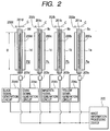
- Fig. 2 is a block diagram of an exposure unit employed in the image forming apparatus according to the present invention.
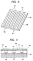
- Fig. 3 is a perspective view of a single-chip light emission element array formed on a single substrate employed in the present invention.
- Fig. 4 is a cross-sectional view of the light emission element array employed in the present invention.
-
- The present invention is firstly featured by an image forming apparatus provided with a photosensitive member, exposure means having a single-chip light emission element array formed by integrating a plurality of light emission elements in a single chip and adapted to execute the entire exposure in the main scanning direction (with a main scanning distance D) relative to the movement of the photosensitive member by the light emission from the single-chip light emission element array, and developing means provided around the photosensitive member.
- The present invention is secondly featured by an image forming apparatus provided with mutually independent photosensitive members, a plurality of single-chip light emission element arrays each of which consists of integrated light emission elements and is obtained by forming light emission element arrays, each consisting of such plurality of light emission elements, in a plurality of rows on a single substrate and mutually separating such plurality of rows of the light emission element arrays, and a plurality of developing means provided respectively around the plurality of photosensitive members.
- In a first preferred embodiment of the present invention, the light emission element is an organic light emission element.
- In a second preferred embodiment of the present invention, the photosensitive member is an organic or inorganic electrophotographic photosensitive member.
- In a third preferred embodiment of the present invention, the above-described mutually independent photosensitive members are respectively shaped as drums and are arrayed linearly.
- In a fourth preferred embodiment of the present invention, the plurality of single-chip light emission element arrays, provided respectively corresponding to the plurality of photosensitive members, are independently connected to first drive means for driving cyan image information for forming a cyan image, second drive means for driving magenta image information for forming a magenta image, and third drive means for driving yellow image information for forming a yellow image.
- In a fifth preferred embodiment of the present invention, the plurality of single-chip light emission element arrays, provided respectively corresponding to the plurality of photosensitive members, are independently connected to first drive means for driving cyan image information for forming a cyan image, second drive means for driving magenta image information for forming a magenta image, third drive means for driving yellow image information for forming a yellow image, and fourth drive means for driving black image information for forming a black image.
- In a sixth preferred embodiment of the present invention, the plurality of developing means comprise first developing means for forming a cyan image, second developing means for forming a magenta image, and third developing means for forming a yellow image which are independently operable each other.
- In a seventh preferred embodiment of the present invention, the plurality of developing means comprise first developing means for forming a cyan image, second developing means for forming a magenta image, third developing means for forming a yellow image, and fourth developing means for forming a black image which are independently operable each other.
- In an eighth preferred embodiment of the present invention, the chip length of the single-chip light emission element array is so selected that the entire main scanning length, relative to the movement of the photosensitive member, can be exposed with such single-chip array.
- In a ninth preferred embodiment of the present invention, the photosensitive members are respectively in the form of a drum having the same diameter.
- In a tenth preferred embodiment of the present invention, the photosensitive members are composed of a same photosensitive layer.
- Now, the present invention will be clarified in detail by preferred embodiments, with reference to the attached drawings. Fig. 1 is across-sectional view of a color electrophotographic copying apparatus, which is the image forming apparatus of the present invention.
- In the illustrated color copying apparatus, a printing medium such as paper is housed in a cassette 6 and is fed to a transport unit from the cassette 6, along the progress of an image forming operation (hereinafter also called printing operation). A
conveyor belt 31, being supported between adriving roller 35 and twoidler rollers roller 35 and therollers belt 31, as thedriving roller 35 is rotated by amotor 38. - Along the
conveyor belt 31, there are provided four image forming units Pa, Pb, Pc and Pd of a similar structure. The configuration of such units will be briefly explained in the following, taking the image forming unit Pa for the first color as an example. - In the image forming unit Pa, a cylindrical photosensitive member or a
photosensitive drum 1a, rotating in a direction of an arrow B, is provided in the vicinity of theconveyor belt 31. In the course of rotation of thephotosensitive drum 1a, a photosensitive layer provided on the surface thereof is uniformly charged by aprimary charger 4a, consisting of a contact charger. Then, the charged photosensitive layer is exposed to a light image of the yellow component of the original image, by the light emission from exposure means 8a consisting of the aforementioned single-chip light emission element array adapted to irradiating the entire main scanning area of the photosensitive drum, thereby forming an electrostatic latent image of the yellow component. The portion bearing such electrostatic latent image moves in succession by its rotation to the position of a yellow developingunit 2a and is rendered visible therein by image development with yellow toner supplied from the yellow developingunit 2a. - The yellow toner image reaches, by the rotation of the
photosensitive drum 1a, a transfer position corresponding to acorona charger 3a, opposed to thedrum 1a across theconveyor belt 31. In synchronization, the printing medium is transported to the transfer position by theconveyor belt 31. Subsequently a transfer bias voltage is applied to thecorona charger 3a, whereby the yellow toner image borne on thephotosensitive drum 1a is transferred onto the printing medium along the rotation of thephotosensitive drum 1. - With the rotation of the
photosensitive drum 1a, the toner remaining therein is eliminated by a cleaning unit (not shown), whereby the photosensitive drum is readied for entering the next image forming cycle. On the other hand, the printing medium bearing the transferred yellow toner image is transported by theconveyor belt 31 to the printing portion composed of the image forming unit Pb of the second color. - The image forming unit Pb of the second color has a configuration similar to that of the image forming unit Pa of the first color, wherein the exposure of the light image of the magenta component of the original image is executed by the light emission from the exposure means 8b employing the single-chip light emission element array in a similar manner as explained above to form an electrostatic latent image of the magenta component. Then the latent image is developed with magenta toner to obtain a magenta toner image which is transferred, in a transfer position, onto the printing medium in superposition with the yellow toner image formed previously. Similarly, in the course of transportation of the printing medium, electrostatic latent images of cyan component and black component are formed in the image forming units Pc and Pd by the light emissions from the exposure means 8c and 8d consisting of the single-chip light emission element arrays, and a cyan toner image and a black toner image respectively formed in these units are transferred in superposition, whereby a color image consisting of superposed four color toner images is obtained on the printing medium.
- As in the image forming unit Pa of the first color, the image forming units Pb, Pc and Pd of the second, third and fourth colors are provided respectively with
photosensitive drums units corona chargers primary chargers - After having passed through the processes in the image forming units Pa, Pb, Pc and Pd, the printing medium bearing the toner images of four colors is further transported, then subjected to charge elimination by a corona separator 7, separated from the
conveyor belt 31 and is transferred to afixing unit 5 provided with afixing roller 51 and apressure roller 52 positioned in a pair. The transferred toner images are fixed by pressurization and heating in a nip portion of therollers - Fig. 2 is a block diagram showing the details of the image forming units Pa, Pb, Pc and Pd shown in Fig. 1.
- In the image forming units Pa, Pb, Pc and Pd, the exposure means 8a, 8b, 8c and 8d positioned respectively corresponding to the
photosensitive drums emission element array 200a for yellow, a lightemission element array 200b for magenta, a lightemission element array 200c for cyan and a lightemission element array 200d for black, which are respectively connected a yellow signal drive circuit (IC) 202a, a magenta signal drive circuit (IC) 202b, a cyan signal drive circuit (IC) 202c and a black signal drive circuit (IC) 202d throughwiring units signal generation circuit 204a, a magentasignal generation circuit 204b, a cyansignal generation circuit 204c and a blacksignal generation circuit 204d. The light emitting elements employed in the above-mentioned yellow, magenta, cyan and black lightemission element arrays - A counter electrode provided in each of the yellow light
emission element array 200a, magenta lightemission element array 200b, cyan lightemission element array 200c and black lightemission element array 200d is utilized as a common electrode, and the timing of respective driving operations is controlled by a yellowcommon drive circuit 203a, a magentacommon drive circuit 203b, a cyancommon drive circuit 203c and a blackcommon drive circuit 203d. The common driving operations, as well as the yellow, magenta, cyan and black image signals, are controlled by an imageinformation processing unit 205 in a CPU (not shown). - For each of the yellow light
emission element array 200a, magenta lightemission element array 200b, cyan lightemission element array 200c and black lightemission element array 200d of the present invention, there is employed a single-chip (one-chip) light emission element array so positioned as to cover the entire main scanning distance D in the main scanning direction relative to the rotating displacement of thephotosensitive drum arrays - In a preferred embodiment of the present invention, the above-described single-chip light emission element arrays employed in the yellow, magenta, cyan and black light
emission element arrays - In Fig. 2, arrows C indicate the sub scanning direction of the rotating photosensitive members. The
photosensitive drums - Fig. 3 is a perspective view of a single-chip light emission
element array substrate 300 provided on asingle glass substrate 303 at a prior step in which single-chip lightemission element arrays 301 employed in the above-described yellow, magenta, cyan and black lightemission element arrays - The
glass substrate 303 to be employed in the present invention may have any size as long as the light emission element arrays can be formed in a single chip. - Fig. 4 is a cross-sectional view of the single-chip light
emission element array 301 in the longitudinal direction thereof, in the single-chip light emissionelement array substrate 300 on theglass substrate 303 shown in Fig. 3. Each light emitting element is composed of asegment electrode 403, acounter electrode 402 and alight emitting layer 401 provided between the pairedelectrodes segment electrode 403 and thelight emitting layer 401 or between thecounter electrode 402 and thelight emitting layer 401. As explained in the foregoing, thecounter electrode 402 is used as a common electrode for applying a common signal, while thesegment electrode 403 is used as an information signal electrode for applying an image signal. The light emitting elements on a single substrate are covered by aprotective layer 404, and asealant 405 is provided for mutually separating the light emitting elements. - The
light emitting layer 401 of the light emitting elements of the present invention is preferably composed of an organic electroluminescent (EL) light emitting element, but it can also be composed of an inorganic EL element. - In the following there will be explained examples of the organic EL that can be employed in the present invention.
- Examples of the materials constituting the organic EL to be employed in the present invention include those disclosed in EP-A-349,265 (1990) assigned to Scozzafava; U.S. Patent No. 4,356,429 assigned to Tang.; U.S. Patent No. 4,539,507 assigned to VanSlyke et al.; U.S. Patent No. 4,720,432 assigned to VanSlyke et al.; U.S. Patent No. 4,769,292 assigned to Tang et al.; U.S. Patent No. 4,885,211 assigned to Tang et al.; U.S. Patent No. 4,950,950 assigned to Perry et al.; U.S. Patent No. 5,059,861 assigned to Littman et al.; U.S. Patent No. 5,047,687 assigned to VanSlyke; U.S. Patent No. 5,073,446 assigned to Scozzafava et al.; U.S. Patent No. 5,059,862 assigned to VanSlyke et al.; U.S. Patent No. 5,061,617 assigned to VanSlyke et al.; U.S. Patent No. 5,151,629 assigned to VanSlyke; U.S. Patent No. 5,294,869 assigned to Tang et al.; and U.S. Patent No. 5,294,870 assigned to Tang et al.
- The EL layer is composed of an organic hole injection/transfer layer in contact with an anode, and an electron injection/transfer layer which forms a junction with the organic hole injection/transfer layer. The hole injection/transfer layer is formed by a single material or plural materials, and is composed of a hole injection layer which is in contact with an anode and with a continuous hole transfer layer provided between the hole injection layer and an electron injection/transfer layer. Similarly the electron injection/transfer layer is formed by a single material or a plurality of materials, and is composed of an electron injection layer which is in contact with the anode and with a continuous electron transfer layer provided between the electron injection layer and the hole injection/transfer layer. The hole-electron recombination and luminescence take place in the electron injection/transfer layer, adjacent to the junction between the electron injection/transfer layer and the hole injection/transfer layer. The compound constituting the organic EL layer is typically deposited by evaporation, but it can also be deposited by other known methods.
- In a preferred embodiment, the organic material constituting the hole injection layer has the following general formula:wherein:

- Q is N or C-R, in which R is an alkyl radical such as methyl or ethyl);
- M is a metal atom, a metal oxide or a metal halide;
- T1 and T2 are independently each other a hydrogen atom, an alkyl radical or a radical of an unsaturated six-membered ring which is unsubstituted or substituted by a substituent such as a halogen atom. A preferred alkyl radical may contains 1 to 6 carbon atoms and a preferred radical of the unsubstituted unsaturated six-membered ring may be an aryl radical such as a phenyl radical.
-
- In a preferred embodiment, the hole transfer layer is composed of an aromatic tertiary amine, of which a preferred sub class includes tetraaryldiamine represented by the following formula:wherein Are is an arylene radical; n is an integer of from 1 to 4; and AR, R7, R8 and R9 are independently each other selected aryl radicals. In a preferred embodiment, the luminescent electron injection/transfer layer contains a metal oxinoid compound, of which preferred examples are represented by the following general formula:
 wherein R2 to R7 respectively mean possible substituents. In another preferred embodiment, the metal oxinoid compound is represented by the following formula:
 wherein R2 to R7 have the same meaning as defined above; and L1 to L5 represent independently each other a hydrogen atom or a hydrocarbon radical containing 1 to 12 carbon atoms, and L1 and L2 or L2 and L3 together may form a fused benzo ring. In another preferred embodiment, the metal oxinoid compound is represented by the following formula:
 wherein R2 to R6 respectively represent a hydrogen atom or a possible substituent. The examples described above merely represent the preferred organic material that can be employed in the electroluminescent layer. Such examples are not intended to limit the scope of the present invention but merely designate the organic electroluminescent layer in general sense. As will be understood from the foregoing examples, the organic EL material contains a coordinate compound having an organic ligand.
- The
segment electrode 403 to be employed in the light emitting element of the present invention can be composed of reflective metal such as aluminum, silver, zinc, gold or chromium, and thecounter electrode 402 can be composed of a transparent conductive film such as Indium Tin Oxide (ITO) or tin oxide. - The
sealant 405 to be employed in the present invention can be composed of inorganic insulating substance such as silicon oxide or silicon nitride, or organic insulating resin such as epoxy resin. Also theprotective film 404 to be employed in the present invention can be composed of a film of an inorganic insulating substance such as silicon oxide or silicon nitride, or organic insulating resin such as epoxy resin. - In the image forming apparatus of the present invention, the photosensitive layer of the
photosensitive members - On the element prepared in the above-described manner, the protective film (404) was prepared by sputtering silicon nitride in a thickness of 150 nm. The steps from the formation of the organic layer to the formation of the protective layer were executed in a same vacuum chamber.
- As the anode of the organic LED there is preferably used a material with a large work function, and may be used, in addition to ITO employed in the present embodiment, for example, tin oxide, gold, platinum, palladium, selenium, iridium or copper iodide.
- On the other hand, as the cathode there is preferably used a material with a small work function, and may be used, in addition to Mg/Ag employed in the present embodiment, for example, Mg, Al, Li, In or alloys thereof.
- As to the hole transport layer there may be used, in addition to TPD, any of the organic substances shown in the following Table 1.
- In addition to such organic substances, there may also be employed an inorganic substance such as a-Si or a-SiC.
- As to the electron transport layer there may be used, in addition to Alq3, any of the substances shown in the following Table 2.
- Also the electron transport layer or the hole transport layer may be doped with a dopant dye shown in the following Table 3.
- The material constituting the organic LED desirably has a light emission spectrum matching the sensitivity of the photosensitive drum to be used.
- On a
glass substrate 303 of 230 mm × 40 mm × 0.7 mm, a metal mask with a line width of 50 µm and a line pitch of 80 µm was placed and ITO was sputtered with a thickness of 100 nm to form theanode 403. The transparent substrate was then subjected to UV ion rinsing treatment for 30 minutes at 150°C. - Then, N,N'-bis(3-methylphenyl)-N,N'-diphenyl-(1,1'-biphenyl)-4,4'-diamine (hereinafter represented as TPD) as the hole transport layer and tris(8-quinolynol)aluminum (hereinafter represented as Alq3) as the electron transport layer were deposited by vacuum deposition with respective thicknesses of 50 nm in this order. The vacuum deposition was executed under vacuum of 1 × 10⁻⁶ torr and with a film forming rate of 0.3 nm/sec. The
organic layer 401 was formed in the above-explained manner. - Then, a metal mask with a line width of 40 µm was placed and Mg and Ag were codeposited with a deposition rate ratio of 10 : 1, whereby a Mg/Ag alloy (Mg:Ag=10:1) was deposited with a thickness of 200 nm to form the
cathode 402. The film forming rate was 1 nm/sec. - The single-chip light emission
element array substrate 300 prepared in this manner was then cut along theseparation lines 302 shown in Fig. 3 to obtain four single-chip lightemission element arrays 301 each having a size of 230 mm × 10 mm. Then a cover glass of a dimension of 220 mm × 5 mm × 0.5 mm was placed on the elements and was sealed with epoxy resin. - The steps from the cutting to the sealing were executed in a nitrogen atmosphere.
- The single-chip light emission element array thus prepared was connected to a driver and was given a DC voltage, with the positive side at the ITO electrode and the negative side at the Mg/Ag electrode, whereby green light was emitted from the intersection of the ITO electrode and the Mg/Ag electrode.
- The four single-chip light emission element arrays thus prepared were measured as to a fluctuation in the amount of light emission among the pixels.
- As a result, the fluctuation in the amount of light emission from each pixels of a single-chip light emission element array was within ±3%, and the fluctuation in the amount of light emission among the four single-chip light emission element arrays was also within ±3%.


- As explained in the foregoing, the present invention employs the novel single-chip light emission element arrays instead of the conventional jointed LED's, thereby reducing the cost of the light emission element array in the image forming apparatus, and improving the color reproducibility in the main scanning direction. Also, since the four single-chip light emission element arrays provided respectively corresponding to the photosensitive members are taken from a single substrate and have therefore substantially equal light emission characteristics, the compensation of the characteristics among the different element arrays can be dispensed with and the cost required therefor can be significantly reduced.
Claims (23)
- An image forming apparatus comprising:a photosensitive member;an exposure means including a single-chip light emission element array formed by integrating a plurality of light emitting elements in a single chip which exposure means executes the exposure in the main scanning direction relative to the movement of the photosensitive member, by the light emission from said single-chip light emission element array; anda developing means provided around said photosensitive member.
- The image forming apparatus according to claim 1, wherein said light emitting element is an organic light emitting element.
- The image forming apparatus according to claim 1, wherein said photosensitive member is an electrophotographic photosensitive member.
- The image forming apparatus according to claim 3, wherein said electrophotographic photosensitive member is an organic electrophotographic photosensitive member.
- The image forming apparatus according to claim 3, wherein said electrophotographic photosensitive member is an inorganic electrophotographic photosensitive member.
- The image forming apparatus according to claim 5, wherein said inorganic electrophotographic photosensitive member is an amorphous silicon electrophotographic photosensitive member.
- An image forming apparatus comprising:a plurality of photosensitive members provided mutually independently;an exposure means including a plurality of single-chip light emission element arrays obtained by forming, on a single substrate, a plurality of light emission element arrays each consisting of a plurality of light emitting elements and separating each of said plurality of light emission element arrays, and constructed by positioning said plurality of single-chip light emission element arrays respectively corresponding to said plurality of photosensitive members; anda plurality of developing means provided respectively around said plurality of photosensitive members.
- The image forming apparatus according to claim 7, wherein said light emitting element is an organic light emitting element.
- The image forming apparatus according to claim 7, wherein said photosensitive member is an electrophotographic photosensitive member.
- The image forming apparatus according to claim 9, wherein said electrophotographic photosensitive member is an organic electrophotographic photosensitive member.
- The image forming apparatus according to claim 9, wherein said electrophotographic photosensitive member is an inorganic electrophotographic photosensitive member.
- The image forming apparatus according to claim 11, wherein said inorganic electrophotographic photosensitive member is an amorphous silicon electrophotographic photosensitive member.
- The image forming apparatus according to claim 7, wherein said photosensitive members disposed independently each other are each in the form of a drum and are arrayed linearly.
- The image forming apparatus according to claim 7, wherein the single-chip light emission element arrays positioned respectively corresponding to said photosensitive members are independently connected to a first drive means for driving cyan image information for forming a cyan image, a second drive means for driving magenta image information for forming a magenta image, and a third drive means for driving yellow image information for forming a yellow image.
- The image forming apparatus according to claim 7, wherein the single-chip light emission element arrays positioned respectively corresponding to said photosensitive members are independently connected to a first drive means for driving cyan image information for forming a cyan image, a second drive means for driving magenta image information for forming a magenta image, a third drive means for driving yellow image information for forming a yellow image, and a fourth drive means for driving black image information for forming a black image.
- The image forming apparatus according to claim 7, wherein said developing means comprise a first developing means for generating a cyan image, a second developing means for generating a magenta image, and a third developing means for generating a yellow image which are independently operable each other.
- The image forming apparatus according to claim 7, wherein said developing means comprise a first developing means for generating a cyan image, a second developing means for generating a magenta image, a third developing means for generating a yellow image, and a fourth developing means for generating a black image which are independently operable each other.
- The image forming apparatus according to claim 7, wherein the chip of said single-chip light emission element array has such a length that the exposure in the main scanning direction relative to the movement of the photosensitive member can be performed with one single chip.
- The image forming apparatus according to claim 7, wherein said photosensitive members are respectively in the form of a drum having the same diameter.
- The image forming apparatus according to claim 7, wherein said photosensitive members are formed from photosensitive layers of the same kind.
- An exposure device (8) for use as exposure means in the image forming apparatus of claim 1, comprising:a linear array (200) of light emitting elements (401-403);a drive circuit array (202) having a respective driver for each light emitting element; anda wiring interface (201) connecting each light emitting element to its respective driver;
characterised in thatsaid linear array is comprised of a single jointless substrate (303) on which are provided said light emitting elements (401-403) spaced apart and spanning a distance not less than the main scanning distance (D) of the image forming apparatus for which it is intended, each light emitting element comprising an anode (403), an electroluminescent composite layer (401) of an organic hole transport layer and an electron transport layer, and a common cathode. - A method of producing a set of exposure devices (8a-8d) for use as exposure means in the image forming apparatus of claim 7, each exposure device comprising a linear array (200) of light emitting elements, a drive circuit array (202) having a respective driver for each light emitting element, and a wiring interface (201) connecting each light emitting element to its respective driver, which method is performed by:forming transparent anode electrodes (403) for each linear array (200) on the surface of a common transparent substrate (303);forming an electroluminescent composite layer (401), comprising an organic hole transparent layer and an electron transparent layer, on each anode electrode (403);infilling the spaces between anode electrodes with a sealant (405);forming a respective common cathode for each linear array;cleaving (302) said common transparent substrate to separate each respective linear array; andassembling each linear array with its respective wiring interface and drive circuit array to complete each exposure device (8a-8d).
- The exposure device of claim 21 or one of the exposure devices (8a-8d) produced by the method of claim 22, arranged in cooperative combination with a photosensitive drum (1a-1d) together with a signal generation circuit (204a-204d) arranged for controlling the drive circuit array (202) thereof, and an image information processing device (205) for controlling operation of said signal generation circuit.
Applications Claiming Priority (3)
| Application Number | Priority Date | Filing Date | Title |
|---|---|---|---|
| JP30861297A JPH11138899A (en) | 1997-11-11 | 1997-11-11 | Image forming system |
| JP308612/97 | 1997-11-11 | ||
| JP30861297 | 1997-11-11 |
Publications (2)
| Publication Number | Publication Date |
|---|---|
| EP0916506A2 true EP0916506A2 (en) | 1999-05-19 |
| EP0916506A3 EP0916506A3 (en) | 1999-09-08 |
Family
ID=17983151
Family Applications (1)
| Application Number | Title | Priority Date | Filing Date |
|---|---|---|---|
| EP98309346A Withdrawn EP0916506A3 (en) | 1997-11-11 | 1998-11-10 | Image forming apparatus |
Country Status (3)
| Country | Link |
|---|---|
| US (1) | US6236416B1 (en) |
| EP (1) | EP0916506A3 (en) |
| JP (1) | JPH11138899A (en) |
Cited By (7)
| Publication number | Priority date | Publication date | Assignee | Title |
|---|---|---|---|---|
| DE10001914A1 (en) * | 2000-01-19 | 2001-07-26 | Heidelberger Druckmasch Ag | Photosensitive material exposure method, has individually controlled light sources each used for exposure of given number of raster points or pixels |
| EP1324156A1 (en) * | 2001-12-25 | 2003-07-02 | Seiko Epson Corporation | Image forming apparatus with an organic electrolumluminescent array exposure head |
| US6731322B2 (en) * | 2000-06-14 | 2004-05-04 | Fuji Photo Film Co., Ltd. | Exposing apparatus |
| WO2004051382A2 (en) * | 2002-12-05 | 2004-06-17 | Matsushita Electric Industrial Co., Ltd. | Image forming apparatus with cooling means for exposing means having a organic electroluminescence element |
| US6844945B2 (en) | 2001-11-30 | 2005-01-18 | Dai Nippon Printing Co., Ltd. | Hologram having authenticating information recorded therein |
| EP1564006A3 (en) * | 2004-02-16 | 2008-03-05 | Seiko Epson Corporation | Line head and image formation apparatus employing the same |
| EP3007243A3 (en) * | 2001-01-15 | 2016-06-15 | Sony Corporation | Light-emitting device and process for production thereof |
Families Citing this family (7)
| Publication number | Priority date | Publication date | Assignee | Title |
|---|---|---|---|---|
| JP3626728B2 (en) * | 2000-05-23 | 2005-03-09 | 長瀬産業株式会社 | Organic EL display and method for manufacturing organic EL display |
| CN100423532C (en) * | 2001-08-09 | 2008-10-01 | 松下电器产业株式会社 | Light for image pickup device and driving device therefor |
| CN1262897C (en) | 2002-08-06 | 2006-07-05 | 精工爱普生株式会社 | Image carrier box, explosure head and image forming apparatus using same |
| CN2682455Y (en) | 2002-08-09 | 2005-03-02 | 精工爱普生株式会社 | Photo lighthead and image forming device using the photo lighthead |
| EP1598199A3 (en) | 2004-05-20 | 2009-05-06 | Seiko Epson Corporation | Line head and image forming apparatus incorporating the same |
| US7486306B2 (en) | 2004-11-29 | 2009-02-03 | Seiko Epson Corporation | Optical writing device and method of manufacturing the same |
| US7663653B2 (en) | 2005-02-24 | 2010-02-16 | Seiko Epson Corporation | Optical head and image forming apparatus incorporating the same |
Citations (8)
| Publication number | Priority date | Publication date | Assignee | Title |
|---|---|---|---|---|
| US4356429A (en) | 1980-07-17 | 1982-10-26 | Eastman Kodak Company | Organic electroluminescent cell |
| US4539507A (en) | 1983-03-25 | 1985-09-03 | Eastman Kodak Company | Organic electroluminescent devices having improved power conversion efficiencies |
| US4720432A (en) | 1987-02-11 | 1988-01-19 | Eastman Kodak Company | Electroluminescent device with organic luminescent medium |
| US4769292A (en) | 1987-03-02 | 1988-09-06 | Eastman Kodak Company | Electroluminescent device with modified thin film luminescent zone |
| US4885211A (en) | 1987-02-11 | 1989-12-05 | Eastman Kodak Company | Electroluminescent device with improved cathode |
| EP0349265A2 (en) | 1988-06-27 | 1990-01-03 | EASTMAN KODAK COMPANY (a New Jersey corporation) | Electroluminescent devices |
| US4950950A (en) | 1989-05-18 | 1990-08-21 | Eastman Kodak Company | Electroluminescent device with silazane-containing luminescent zone |
| US5059861A (en) | 1990-07-26 | 1991-10-22 | Eastman Kodak Company | Organic electroluminescent device with stabilizing cathode capping layer |
Family Cites Families (26)
| Publication number | Priority date | Publication date | Assignee | Title |
|---|---|---|---|---|
| JPS5714058A (en) * | 1980-06-28 | 1982-01-25 | Ricoh Co Ltd | Printer |
| US4721977A (en) * | 1984-11-26 | 1988-01-26 | Kentek Information Systems, Inc. | Electrographic printer with abutting chips each having an array of charge-discharging elements |
| EP0238095A1 (en) * | 1986-03-20 | 1987-09-23 | Minolta Camera Kabushiki Kaisha | Photosensitive member composed of charge transporting layer and charge generating layer |
| GB8722946D0 (en) * | 1987-09-30 | 1987-11-04 | Plessey Co Plc | Light emitting diode array |
| EP0335553B1 (en) | 1988-03-18 | 1999-09-15 | Nippon Sheet Glass Co., Ltd. | Self-scanning light-emitting element array |
| US5257049A (en) | 1990-07-03 | 1993-10-26 | Agfa-Gevaert N.V. | LED exposure head with overlapping electric circuits |
| US5047687A (en) | 1990-07-26 | 1991-09-10 | Eastman Kodak Company | Organic electroluminescent device with stabilized cathode |
| US5059862A (en) | 1990-07-26 | 1991-10-22 | Eastman Kodak Company | Electroluminescent device with improved cathode |
| US5073446A (en) | 1990-07-26 | 1991-12-17 | Eastman Kodak Company | Organic electroluminescent device with stabilizing fused metal particle cathode |
| US5061617A (en) | 1990-12-07 | 1991-10-29 | Eastman Kodak Company | Process for the preparation of high chloride tabular grain emulsions |
| US5151629A (en) | 1991-08-01 | 1992-09-29 | Eastman Kodak Company | Blue emitting internal junction organic electroluminescent device (I) |
| US5300961A (en) | 1991-12-16 | 1994-04-05 | Xerox Corporation | Method and apparatus for aligning multiple print bars in a single pass system |
| US5294869A (en) | 1991-12-30 | 1994-03-15 | Eastman Kodak Company | Organic electroluminescent multicolor image display device |
| US5294870A (en) | 1991-12-30 | 1994-03-15 | Eastman Kodak Company | Organic electroluminescent multicolor image display device |
| DE4303225C2 (en) * | 1993-02-04 | 1996-08-14 | Siemens Nixdorf Inf Syst | Optical character generator for an electrographic printer |
| US5339150A (en) | 1993-03-23 | 1994-08-16 | Xerox Corporation | Mark detection circuit for an electrographic printing machine |
| JPH06302855A (en) | 1993-03-29 | 1994-10-28 | Minnesota Mining & Mfg Co <3M> | Optical scanning device |
| JPH07140753A (en) | 1993-11-19 | 1995-06-02 | Fujitsu Ltd | Color image forming device |
| JPH07314771A (en) | 1994-05-20 | 1995-12-05 | Sharp Corp | Led write device |
| JPH0848052A (en) * | 1994-08-09 | 1996-02-20 | Oki Electric Ind Co Ltd | Optical printing head having el array |
| JP3452982B2 (en) * | 1994-08-24 | 2003-10-06 | ローム株式会社 | LED print head, LED array chip, and method of manufacturing the LED array chip |
| JPH0890832A (en) | 1994-09-27 | 1996-04-09 | Oki Electric Ind Co Ltd | Light emitting element array and optical head |
| JP3385134B2 (en) * | 1994-11-14 | 2003-03-10 | 株式会社沖データ | Electrophotographic recording device |
| JP3194423B2 (en) * | 1996-05-30 | 2001-07-30 | キヤノン株式会社 | Image forming device |
| JP3703234B2 (en) * | 1996-12-24 | 2005-10-05 | キヤノン株式会社 | Image recording device |
| JP2942230B2 (en) * | 1998-01-12 | 1999-08-30 | キヤノン株式会社 | Image forming apparatus and light emitting device |
-
1997
- 1997-11-11 JP JP30861297A patent/JPH11138899A/en active Pending
-
1998
- 1998-11-06 US US09/187,398 patent/US6236416B1/en not_active Expired - Lifetime
- 1998-11-10 EP EP98309346A patent/EP0916506A3/en not_active Withdrawn
Patent Citations (8)
| Publication number | Priority date | Publication date | Assignee | Title |
|---|---|---|---|---|
| US4356429A (en) | 1980-07-17 | 1982-10-26 | Eastman Kodak Company | Organic electroluminescent cell |
| US4539507A (en) | 1983-03-25 | 1985-09-03 | Eastman Kodak Company | Organic electroluminescent devices having improved power conversion efficiencies |
| US4720432A (en) | 1987-02-11 | 1988-01-19 | Eastman Kodak Company | Electroluminescent device with organic luminescent medium |
| US4885211A (en) | 1987-02-11 | 1989-12-05 | Eastman Kodak Company | Electroluminescent device with improved cathode |
| US4769292A (en) | 1987-03-02 | 1988-09-06 | Eastman Kodak Company | Electroluminescent device with modified thin film luminescent zone |
| EP0349265A2 (en) | 1988-06-27 | 1990-01-03 | EASTMAN KODAK COMPANY (a New Jersey corporation) | Electroluminescent devices |
| US4950950A (en) | 1989-05-18 | 1990-08-21 | Eastman Kodak Company | Electroluminescent device with silazane-containing luminescent zone |
| US5059861A (en) | 1990-07-26 | 1991-10-22 | Eastman Kodak Company | Organic electroluminescent device with stabilizing cathode capping layer |
Cited By (9)
| Publication number | Priority date | Publication date | Assignee | Title |
|---|---|---|---|---|
| DE10001914A1 (en) * | 2000-01-19 | 2001-07-26 | Heidelberger Druckmasch Ag | Photosensitive material exposure method, has individually controlled light sources each used for exposure of given number of raster points or pixels |
| US6731322B2 (en) * | 2000-06-14 | 2004-05-04 | Fuji Photo Film Co., Ltd. | Exposing apparatus |
| EP3007243A3 (en) * | 2001-01-15 | 2016-06-15 | Sony Corporation | Light-emitting device and process for production thereof |
| US6844945B2 (en) | 2001-11-30 | 2005-01-18 | Dai Nippon Printing Co., Ltd. | Hologram having authenticating information recorded therein |
| EP1324156A1 (en) * | 2001-12-25 | 2003-07-02 | Seiko Epson Corporation | Image forming apparatus with an organic electrolumluminescent array exposure head |
| WO2004051382A2 (en) * | 2002-12-05 | 2004-06-17 | Matsushita Electric Industrial Co., Ltd. | Image forming apparatus with cooling means for exposing means having a organic electroluminescence element |
| WO2004051382A3 (en) * | 2002-12-05 | 2004-11-18 | Matsushita Electric Ind Co Ltd | Image forming apparatus with cooling means for exposing means having a organic electroluminescence element |
| US7116345B2 (en) | 2002-12-05 | 2006-10-03 | Matsushita Electric Industrial Co., Ltd. | Image forming apparatus having a cooler for an organic electroluminescence element |
| EP1564006A3 (en) * | 2004-02-16 | 2008-03-05 | Seiko Epson Corporation | Line head and image formation apparatus employing the same |
Also Published As
| Publication number | Publication date |
|---|---|
| EP0916506A3 (en) | 1999-09-08 |
| US6236416B1 (en) | 2001-05-22 |
| JPH11138899A (en) | 1999-05-25 |
Similar Documents
| Publication | Publication Date | Title |
|---|---|---|
| JP2942230B2 (en) | Image forming apparatus and light emitting device | |
| EP0916506A2 (en) | Image forming apparatus | |
| US6504565B1 (en) | Light-emitting device, exposure device, and image forming apparatus | |
| US6794816B2 (en) | Organic EL panel and the manufacture thereof | |
| US8427517B2 (en) | Light-emitting element, exposure head and image-forming apparatus | |
| US6573920B2 (en) | Method of manufacturing a printer with an electroluminescent (EL) pixel array | |
| EP1009046B1 (en) | Light emitting element array, method of forming the array and image forming apparatus | |
| JP3039778B2 (en) | Image forming device | |
| US6133933A (en) | Color Xerographic printing system with multicolor printbar | |
| JP2000277253A (en) | Luminous element, light emitting device, display device, aligner, and image forming device | |
| JP2007311752A (en) | Light-emitting device and manufacturing method therefor | |
| JP2007290329A (en) | Light-receiving element, light-emitting device, light head and image forming apparatus | |
| JP3631074B2 (en) | Light emitting device | |
| JP4143180B2 (en) | Multicolor image forming apparatus | |
| JP2007283491A (en) | Light emitting element, light emitting device using this light emitting element, optical head and image forming apparatus | |
| JP2003341141A (en) | Optical head and imaging apparatus using the same | |
| JP4154045B2 (en) | Image forming apparatus | |
| JP4541535B2 (en) | Organic light emitting diode array for optical head | |
| JPS59102259A (en) | Electrophotography recording device | |
| JP2000289249A (en) | Exposing unit and imaging apparatus employing it | |
| JPH08244272A (en) | Optical printer head | |
| JPH0848052A (en) | Optical printing head having el array | |
| JP2000127491A (en) | Exposure device and image forming device | |
| JP2007294944A (en) | Method of manufacturing sealing body, method of manufacturing light emitting device using the same, sealing body, light emitting device, exposure device and image forming device using the exposure device | |
| JP2007290393A (en) | Exposure device and image forming apparatus using it |
Legal Events
| Date | Code | Title | Description |
|---|---|---|---|
| PUAI | Public reference made under article 153(3) epc to a published international application that has entered the european phase |
Free format text: ORIGINAL CODE: 0009012 |
|
| AK | Designated contracting states |
Kind code of ref document: A2 Designated state(s): DE FR GB NL |
|
| AX | Request for extension of the european patent |
Free format text: AL;LT;LV;MK;RO;SI |
|
| PUAL | Search report despatched |
Free format text: ORIGINAL CODE: 0009013 |
|
| AK | Designated contracting states |
Kind code of ref document: A3 Designated state(s): AT BE CH CY DE DK ES FI FR GB GR IE IT LI LU MC NL PT SE |
|
| AX | Request for extension of the european patent |
Free format text: AL;LT;LV;MK;RO;SI |
|
| RIC1 | Information provided on ipc code assigned before grant |
Free format text: 6B 41J 2/45 A, 6G 03G 5/07 B |
|
| 17P | Request for examination filed |
Effective date: 20000121 |
|
| AKX | Designation fees paid |
Free format text: DE FR GB NL |
|
| 17Q | First examination report despatched |
Effective date: 20030218 |
|
| STAA | Information on the status of an ep patent application or granted ep patent |
Free format text: STATUS: THE APPLICATION IS DEEMED TO BE WITHDRAWN |
|
| 18D | Application deemed to be withdrawn |
Effective date: 20030701 |