EP0915529A1 - Positionierbare Satellitenantenne mit wiederkonfigurierbarer Richtcharakteristik - Google Patents
Positionierbare Satellitenantenne mit wiederkonfigurierbarer Richtcharakteristik Download PDFInfo
- Publication number
- EP0915529A1 EP0915529A1 EP98309113A EP98309113A EP0915529A1 EP 0915529 A1 EP0915529 A1 EP 0915529A1 EP 98309113 A EP98309113 A EP 98309113A EP 98309113 A EP98309113 A EP 98309113A EP 0915529 A1 EP0915529 A1 EP 0915529A1
- Authority
- EP
- European Patent Office
- Prior art keywords
- feed
- antenna
- feed elements
- reflector
- earth
- Prior art date
- Legal status (The legal status is an assumption and is not a legal conclusion. Google has not performed a legal analysis and makes no representation as to the accuracy of the status listed.)
- Withdrawn
Links
Images

Classifications
-
- H—ELECTRICITY
- H01—ELECTRIC ELEMENTS
- H01Q—ANTENNAS, i.e. RADIO AERIALS
- H01Q3/00—Arrangements for changing or varying the orientation or the shape of the directional pattern of the waves radiated from an antenna or antenna system
- H01Q3/26—Arrangements for changing or varying the orientation or the shape of the directional pattern of the waves radiated from an antenna or antenna system varying the relative phase or relative amplitude of energisation between two or more active radiating elements; varying the distribution of energy across a radiating aperture
- H01Q3/2658—Phased-array fed focussing structure
-
- H—ELECTRICITY
- H01—ELECTRIC ELEMENTS
- H01Q—ANTENNAS, i.e. RADIO AERIALS
- H01Q1/00—Details of, or arrangements associated with, antennas
- H01Q1/27—Adaptation for use in or on movable bodies
- H01Q1/28—Adaptation for use in or on aircraft, missiles, satellites, or balloons
- H01Q1/288—Satellite antennas
-
- H—ELECTRICITY
- H01—ELECTRIC ELEMENTS
- H01Q—ANTENNAS, i.e. RADIO AERIALS
- H01Q19/00—Combinations of primary active antenna elements and units with secondary devices, e.g. with quasi-optical devices, for giving the antenna a desired directional characteristic
- H01Q19/10—Combinations of primary active antenna elements and units with secondary devices, e.g. with quasi-optical devices, for giving the antenna a desired directional characteristic using reflecting surfaces
- H01Q19/12—Combinations of primary active antenna elements and units with secondary devices, e.g. with quasi-optical devices, for giving the antenna a desired directional characteristic using reflecting surfaces wherein the surfaces are concave
- H01Q19/17—Combinations of primary active antenna elements and units with secondary devices, e.g. with quasi-optical devices, for giving the antenna a desired directional characteristic using reflecting surfaces wherein the surfaces are concave the primary radiating source comprising two or more radiating elements
-
- H—ELECTRICITY
- H01—ELECTRIC ELEMENTS
- H01Q—ANTENNAS, i.e. RADIO AERIALS
- H01Q3/00—Arrangements for changing or varying the orientation or the shape of the directional pattern of the waves radiated from an antenna or antenna system
- H01Q3/02—Arrangements for changing or varying the orientation or the shape of the directional pattern of the waves radiated from an antenna or antenna system using mechanical movement of antenna or antenna system as a whole
- H01Q3/08—Arrangements for changing or varying the orientation or the shape of the directional pattern of the waves radiated from an antenna or antenna system using mechanical movement of antenna or antenna system as a whole for varying two co-ordinates of the orientation
-
- H—ELECTRICITY
- H01—ELECTRIC ELEMENTS
- H01Q—ANTENNAS, i.e. RADIO AERIALS
- H01Q3/00—Arrangements for changing or varying the orientation or the shape of the directional pattern of the waves radiated from an antenna or antenna system
- H01Q3/12—Arrangements for changing or varying the orientation or the shape of the directional pattern of the waves radiated from an antenna or antenna system using mechanical relative movement between primary active elements and secondary devices of antennas or antenna systems
- H01Q3/16—Arrangements for changing or varying the orientation or the shape of the directional pattern of the waves radiated from an antenna or antenna system using mechanical relative movement between primary active elements and secondary devices of antennas or antenna systems for varying relative position of primary active element and a reflecting device
-
- H—ELECTRICITY
- H01—ELECTRIC ELEMENTS
- H01Q—ANTENNAS, i.e. RADIO AERIALS
- H01Q3/00—Arrangements for changing or varying the orientation or the shape of the directional pattern of the waves radiated from an antenna or antenna system
- H01Q3/24—Arrangements for changing or varying the orientation or the shape of the directional pattern of the waves radiated from an antenna or antenna system varying the orientation by switching energy from one active radiating element to another, e.g. for beam switching
- H01Q3/245—Arrangements for changing or varying the orientation or the shape of the directional pattern of the waves radiated from an antenna or antenna system varying the orientation by switching energy from one active radiating element to another, e.g. for beam switching in the focal plane of a focussing device
-
- H—ELECTRICITY
- H04—ELECTRIC COMMUNICATION TECHNIQUE
- H04B—TRANSMISSION
- H04B7/00—Radio transmission systems, i.e. using radiation field
- H04B7/14—Relay systems
- H04B7/15—Active relay systems
- H04B7/185—Space-based or airborne stations; Stations for satellite systems
- H04B7/1851—Systems using a satellite or space-based relay
- H04B7/18519—Operations control, administration or maintenance
-
- H—ELECTRICITY
- H04—ELECTRIC COMMUNICATION TECHNIQUE
- H04B—TRANSMISSION
- H04B7/00—Radio transmission systems, i.e. using radiation field
- H04B7/14—Relay systems
- H04B7/15—Active relay systems
- H04B7/204—Multiple access
- H04B7/2041—Spot beam multiple access
Definitions
- This invention relates to mechanically steerable antennas, suitable for use on board a communications satellite encircling the earth and, more particularly, to an antenna having an array of feed elements illuminating a reflector wherein the reflector is a shaped-beam reflector and wherein, upon a repositioning of the antenna relative to the satellite, there is an adjustment of the beam configuration.
- one or more antennas on board the satellite direct beams of radiation to selected locations on the earth's surface as the satellite progresses in a stationary orbit about the earth. Based on considerations of communication traffic, it may be desirable to reorient an antenna relative to the body of the satellite so as to illuminate another portion of the earth's surface.
- Each portion of the earth's surface to be illuminated is characterized by a desired beam footprint designating the specific area of the earth's surface wherein are located receiving and/or transmitting stations which are to communicate with the satellite via the antenna.
- the antenna includes both a reflector and an array of feeds which illuminate the reflector to produce a beam configuration and corresponding footprint. However, with a repositioning of the antenna to illuminate different regions of the earth, it is desirable frequently to adjust the configuration of the footprint to meet local traffic conditions.
- two antennas on board a single satellite may be directed to illuminate various areas of the earth's surface in footprints configured to overlap edge regions of neighbouring footprints.
- antennas carried by different satellites may cooperate by illuminating various areas of the earth's surface wherein footprints from the beams of the various antennas are to overlap slightly at the peripheral regions of the respective beam footprints.
- the configurations of the various footprints may vary, depending on the viewing angles by which the satellite directs the beam to the earth.
- the footprints may vary such that a relatively small populated region of the earth may be assigned to one beam. A much larger region of the earth of relatively sparse population may employ a single antenna covering the larger region. Therefore, upon a repositioning of a beam, it may be necessary to provide for adjustment of the beam configuration.
- the present invention seeks to improve the capability for adjustment of footprint configuration by means of an antenna system suitable for being carried by a satellite.
- an antenna system suitable for being carried on board a satellite travelling about the earth, the antenna system including an antenna comprising a reflector and an array of feed elements which illuminate the reflector to produce a beam of radiation emitted by the antenna, the system comprising positioning means operative to orient the antenna relative to a body of the satellite for illuminating a desired position of the earth with the beam, a beam controller having a feed network for applying signals to respective ones of the feed elements, wherein the reflector is a shaped reflector operative with the feed elements to produce a beam footprint, and the beam controller is operative to adjust the configuration of the beam to reconfigure the beam footprint to provide a desired footprint on the surface of the earth and the beam controller adjusts relative amplitudes and phases of signals fed to respective ones of the feed elements.
- the system may include an antenna which comprises a reflector illuminated by an array of feed elements, the array being much smaller than a diameter of the reflector.
- the reflector has the general shape of a section of an ellipsoid or parabola, by way of example, and the reflector is further shaped to provide for a specific configuration of beam.
- the beam configuration Upon deployment of a satellite encircling the earth, the beam configuration produces a footprint on the surface of the earth.
- An antenna positioning mechanism is provided for moving the antenna relative to a body of the spacecraft.
- a repositioning of the beam results in illumination of a different portion of the earth's surface with a possible consequential need for an adjustment of the configuration of the beam footprint upon the earth's surface.
- the invention provides for adjustment of the configuration of the beam configuration. Such adjustment may be by adjustment of relative signal strengths and for phase shifts among signals of elements of the feed. Due to the relatively small size of the array of feed elements, relative to the diameter of the reflector, the primary contribution to the configuration of the beam is the geometry of the reflector. An offsetting in the position of one feed element relative to another feed element results in an inclination of their respective beams relative to each other.
- Summation of the electric and magnetic fields of the respective beams produces a resultant beam having a footprint different from the footprint of any one of the beams.
- Adjustment of the relative phases and/or amplitudes of the signals of the respective feed elements results in an adjustment of the configuration of the resultant beam to suit a specific situation to be handled by the communication satellite.
- Beam control circuitry suitable for adjustment of the beam configuration typically comprises a set of adjustable power dividers and adjustable phase shifters connected in a network for applying the desired signals to respective ones of the elements of the feed. Adjustment occurs by multiple steps to approximate a continuously variable (analog) form of adjustment. Operation of the power dividers and of the phase shifters may be controlled electronically by means of digital coefficients stored in a memory wherein specific sets of coefficients have been previously established for development of a specific beam footprint. New footprint configurations can be developed by sensing beam intensity at various locations on the earth's surface and calculating, via simulation on a computer, the necessary coefficients for the new footprint. These coefficients can then be transmitted to the satellite for storage in the memory.
- Fig. 1 shows a satellite 10 carrying an antenna system 10A which includes an antenna 12 affixed to a body 14 of the satellite 10 by a positioning mechanism 16.
- the positioning mechanism 16 serves to pivot the antenna 12 relative to the body 14 to provide for an orientation of the antenna 12 in a desired direction relative to the satellite 10.
- the antenna 12 comprises a reflector 18 and an array 20 of feed elements 22 which illuminate a front concave side of the reflector 18.
- a frame 24 extends from a base portion of the reflector 18 for supporting the feed elements 22 at a location at or near a focus of the reflector 18 and offset from an axis of a main beam of the reflector 18.
- the satellite 10 is constructed in conventional fashion, and includes electronic circuitry 26 powered with electric power provided by solar panels 28 carried by the satellite 10.
- the electronic circuitry 26 serves to generate electromagnetic signals radiated as a beam 30 from the antenna 12, and to control a cross-sectional shape of the beam 30.
- Alternative positions of the beam 30 are indicated at 32 and 34, which alternative positions result from a pivoting of the antenna 12 by the positioning mechanism 16.
- the satellite 10 travels in an orbit about the earth 36 with the antenna 12 facing the earth for illumination of a portion of the earth's surface by the beam 30.
- illumination of another portion of the earth's surface is accomplished via the beam 32 or the beam 34, by way of example.
- an actual footprint 38 of an illumination pattern is shown in solid line while a desired configuration of the footprint is indicated by a dashed line at 40.
- Various ground stations 42 are shown at different locations on the earth's surface for receiving radiated signals (down-link) transmitted from the satellite 10, and for transmitting signals (up-link) to the satellite 10.
- One of the ground stations 42, namely station 42A may be provided with a computer 44 for calculation of a desired set of coefficients for control of beam cross section, in accordance with the invention, as will be described hereinafter.
- the electronics unit 26 comprises a feed network 46 connecting with an assembly 48 of the feed elements 22 for imparting phase and amplitude to each of the respective signals that are applied to various ones of the feed elements 22.
- a driver 50 is responsive to coefficients of phase and amplitude stored within a memory 52 for driving variable power dividers and variable phase shifters of the feed network 46 (as will be described in Fig. 3) to impart the desired relative amplitudes and relative phases among the signals of the various feed elements 22.
- a transmit/receive unit 53 which includes a receiver 54 of up-link signals and a transmitter 55 of down-link signals, a command and control receiver 56, and a communications control unit 58.
- the receivers 54 and 56 and the transmitter 55 connect with the feed assembly 48 via the feed network 46.
- the control unit 58 connects with the command and control receiver 56 and the transmit/receive unit 53.
- the feed network 46 is operative to pass both up-link signals from the feed assembly 48 to the transceiver 54 and down-link signals from the transceiver 54 to the feed assembly 48.
- the feed network 46 imparts various phases and amplitudes to signals of respective ones of the feed elements 22, in a manner to be described with reference to Fig. 3, to provide a desired cross-sectional configuration to a beam, such as the beam 30 (Fig. 1) produced by the antenna 12.
- the transmit/receive unit 53 is operative in response to signals of the communications control unit 58 for receiving up-link signals in various up-link channels and for retransmitting the signals as down-link signals in various down-link channels.
- command and control signals to the receiver 56 for operation of the positioning mechanism 16 to direct a specific orientation of the antenna 12, for selecting coefficients of the memory 52 to configure a beam such as the beam 30, and for instructing the communications control unit 58 in the handling of communications traffic.
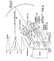
- Fig. 3 shows details in the construction of the antenna 12 including also details in the construction of the feed network 46 connecting with the feed elements 22 of the antenna 12, four of the feed elements 22 being shown by way of example.
- the feed network 46 comprises a transmit portion 46A and a receive portion 46B.
- the network transmit portion 46A comprises a plurality of variable phase shifters (VPS) 60 of which individual ones are further identified as 60A, 60B, 60C and 60D, and a plurality of variable power dividers (VPD) 62 of which individual ones thereof are further identified as 62A, 62B and 62C.
- the array 20 of the feed elements 22 is positioned, preferably, at a focal point 64 of the reflector 18.
- the reflector 18 serves the function of gathering and collimating the rays of radiation emitted by respective ones of the feed elements 22 to produce desired beams of radiation.
- Each of the respective feed elements 22 also acts with the reflector 18 to produce a beam of radiation, four such beams being shown, by way of example, as beams 66 disposed symmetrically about an axis 68 of an array of the beams.
- the network receive portion 46B is constructed in a fashion analogous to the construction of the network transmit portion 46A, and may include phase shifters (not shown) for setting relative phases among received signals of the feed elements 22, and power combiners (not shown) for combining received signals of the various feed elements 22 to form the received beam.
- signal separators 70 interconnect respective ones of the feed elements 22 with both the transmit portion 46A and the receive portion 46B of the network 46.
- a signal separator 70 may be an orthogonal mode junction (OMJ) for the case of orthogonally polarized transmit and received signals, or a diplexer in the case of copolarized signals.
- OMJ orthogonal mode junction
- the electric and the magnetic fields of respective ones of the beams 66 sum together in the far field of the reflector 18 to produce a beam, such as the beam 30 in Fig. 1, having a desired cross-sectional configuration.
- the radiating aperture of the reflector 18 is greater than the radiating aperture of the feed array 20, at least by a factor of approximately ten for improved directivity of the beam 30, a factor in the range of 50-100 being used in a preferred embodiment of the invention.
- Adjustment of relative phases and amplitude of the signals emitted by each of the feed elements 22, with respect to each other effects the summation of the electric and magnetic fields of the beams 66 for control of the cross-sectional configuration of the resulting beam 30.
- the operation of the feed network 46 may be described with respect to the transmission of a down-link signal via the network transmit portion 46A.
- a transmitter 55 outputs the down-link signal to power divider 62A which operates to divide the power of the signal between power dividers 62B and 62C.
- the power divider 62B provides for a further division of the signal power among two signal channels, and the power divider 62C operates similarly to divide its signal power among two further signal channels.
- Each of the signal channels comprises a phase shifter 60 and a feed element 22.
- Power for the first signal channel is provided by the power divider 62B in concert with the phase shifter 60A
- power for the second signal channel is provided by the power divider 62B in concert with the phase shifter 60B
- power for the third signal channel is provided by the power divider 62C in concert with the phase shifter 60C
- power for the fourth signal channel is provided by the power divider 62C in concert with the phase shifter 60D.
- Control signal lines are provided for respective ones of the power dividers 62 and the phase shifters 60 of the network transmit portion 46A, and also for the variable phase shifters and the variable power combiners (not shown) of the network receive portion 46B.
- the control signal lines connect with the driver 50 to enable the driver 50 to communicate, in the case of transmitted signals, with the respective power dividers 62 and phase shifters 60 for commanding the respective power dividers 62 and phase shifters 60 to provide, respectively, desired power divisions among the signal channels.
- Corresponding operation of the driver applies for control of the components of the network receive portion 46B for the case of received signals.
- the command and control receiver 56 supplies the phase and amplitude coefficients to the memory 52 in accordance with instructions received from the ground station 42A.
- the memory 52 is also provided with coefficients of phase and amplitude prior to a launching of the satellite 10, which coefficients serve to define a beam configuration in the absence of specific requests by the ground station 42A. This allows ground control to establish the setting of any of the variable components of the network 46 to obtain any of numerous beam shapes.
- the memory 52 in conjunction with the driver 50 and the feed network 46, serves as a beam controller for controlling the configuration of the beam 30 radiated by the antenna 12.
- the command and control receiver 56 outputs two forms of signals, one form of signal being the coefficients to be stored in memory 52, and the other form of signal being an address for addressing the memory 52 to output a specific set of the coefficients to the driver 50 for accomplishing the desired beam configuration.
- the command and control receiver 56 also serves as a director of antenna orientation by commanding the positioning mechanism 16 to orient the antenna 12 with a desired orientation relative to the body 14 of the satellite 10.
- the shaped reflector 18 focuses radiation from respective ones of the feeds 22 to produce beams which sum together to give a scanned beam 72 of desired cross-sectional configuration.
- the specific locations of the feeds 22 is a matter of choice in the design of the antenna 12 for performance of a specific mission but, in a typical situation, the feeds 22 would be spaced apart by one to two wavelengths of the radiation emitted by the antenna 12, and the radiating aperture of an individual feed element would be approximately one wavelength in diameter.
- the number of the feeds 22 is also determined by the mission of the satellite and the amount of control desired over peripheral regions of the beam footprint on the earth's surface. Thus, for very fine adjustment of the footprint, by way of example, a larger number of the feeds 22 would be employed.
- the feeds 22 may be distributed uniformly about the focal point 64 or, if adjustments are to be made primarily in an east-west direction of the footprint, by way of example, more of the feeds 22 may be disposed horizontally than vertically in the assembly 48 (Fig. 2). Continuous adjustment of the phase shifters 60 may be attained by either analog or digital circuitry, as is well known in the construction of phase shifters.
- control of power division of the power dividers 62 for continuous adjustment of power ratios may be attained either by analog or digital circuitry, such circuitry being well known for adjustment of power ratios.
- the invention is able to redirect a beam of radiation while controlling the configuration of the beam cross section.
Applications Claiming Priority (2)
| Application Number | Priority Date | Filing Date | Title |
|---|---|---|---|
| US08/966,122 US5949370A (en) | 1997-11-07 | 1997-11-07 | Positionable satellite antenna with reconfigurable beam |
| US966122 | 1997-11-07 |
Publications (1)
| Publication Number | Publication Date |
|---|---|
| EP0915529A1 true EP0915529A1 (de) | 1999-05-12 |
Family
ID=25510942
Family Applications (1)
| Application Number | Title | Priority Date | Filing Date |
|---|---|---|---|
| EP98309113A Withdrawn EP0915529A1 (de) | 1997-11-07 | 1998-11-06 | Positionierbare Satellitenantenne mit wiederkonfigurierbarer Richtcharakteristik |
Country Status (2)
| Country | Link |
|---|---|
| US (1) | US5949370A (de) |
| EP (1) | EP0915529A1 (de) |
Cited By (19)
| Publication number | Priority date | Publication date | Assignee | Title |
|---|---|---|---|---|
| EP1076377A2 (de) * | 1999-08-11 | 2001-02-14 | Hughes Electronics Corporation | System zum Ausrichten einer Satellitenantenne |
| US6192217B1 (en) | 1999-07-01 | 2001-02-20 | Assuresat, Inc. | Universal replacement communications satellite |
| DE19945062A1 (de) * | 1999-09-20 | 2001-04-12 | Daimler Chrysler Ag | Reflektor mit geformter Oberfläche und räumlich getrennten Foki zur Ausleuchtung identischer Gebiete, Antennensystem und Verfahren zur Oberflächenermittlung |
| EP1223691A2 (de) * | 2001-01-12 | 2002-07-17 | TRW Inc. | Verfahren und Gerät zur Steuerung der Konfiguration der Antennastrahlen in einem Kommunikationssatellit |
| KR100350938B1 (ko) * | 1999-06-29 | 2002-08-28 | 티알더블류 인코포레이티드 | 무선 주파수 빔 조향을 위한 방법 및 장치 |
| EP1317782A1 (de) * | 2000-07-10 | 2003-06-11 | Andrew Corporation | Zellulare antenne |
| WO2007007011A2 (fr) * | 2005-07-13 | 2007-01-18 | Thales | Antenne reseau a reflecteur(s) conforme(s), a forte reconfigurabilite en orbite |
| WO2007082721A2 (en) * | 2006-01-18 | 2007-07-26 | M.N.C. Microsat Networks (Cyprus) Limited | Systems and methods for tracking mobile terrestrial terminals for satellite communications |
| US7327698B1 (en) | 1999-06-03 | 2008-02-05 | The Directv Group, Inc. | Method and system for providing satellite communications using on-orbit payload configuration and reconfiguration |
| US7962134B2 (en) | 2006-01-18 | 2011-06-14 | M.N.C. Microsat Networks (Cyprus) Limited | Systems and methods for communicating with satellites via non-compliant antennas |
| US8050628B2 (en) | 2007-07-17 | 2011-11-01 | M.N.C. Microsat Networks (Cyprus) Limited | Systems and methods for mitigating radio relay link interference in mobile satellite communications |
| US8078141B2 (en) | 2006-01-18 | 2011-12-13 | Overhorizon (Cyprus) Plc | Systems and methods for collecting and processing satellite communications network usage information |
| CN102427169A (zh) * | 2011-08-30 | 2012-04-25 | 四川大学 | 微波合束发射装置 |
| US8326217B2 (en) | 2006-01-18 | 2012-12-04 | Overhorizon (Cyprus) Plc | Systems and methods for satellite communications with mobile terrestrial terminals |
| US8713324B2 (en) | 2006-01-18 | 2014-04-29 | Overhorizon (Cyprus) Plc | Systems and methods for tracking mobile terrestrial terminals for satellite communications |
| US8948080B2 (en) | 2007-07-17 | 2015-02-03 | Overhorizon (Cyprus) Plc | Methods comprising satellites having a regenerative payload, onboard computer, payload interface and interference elimination system |
| WO2015082000A1 (en) * | 2013-12-04 | 2015-06-11 | Telefonaktiebolaget L M Ericsson (Publ) | A wireless communication system node with re-configurable antenna devices |
| EP2919321A4 (de) * | 2012-11-07 | 2016-07-06 | Mitsubishi Electric Corp | Arraygespeiste reflektorantennenvorrichtung und herstellungsverfahren dafür |
| WO2016146160A1 (en) * | 2015-03-16 | 2016-09-22 | Telefonaktiebolaget Lm Ericsson (Publ) | Mimo link between wireless communication nodes |
Families Citing this family (25)
| Publication number | Priority date | Publication date | Assignee | Title |
|---|---|---|---|---|
| US6289004B1 (en) * | 1998-03-12 | 2001-09-11 | Interdigital Technology Corporation | Adaptive cancellation of fixed interferers |
| FR2815323B1 (fr) * | 2000-10-16 | 2003-01-31 | Cit Alcatel | Perfectionnements apportes aux satellites geostationnaires |
| US7639196B2 (en) * | 2001-07-10 | 2009-12-29 | Andrew Llc | Cellular antenna and systems and methods therefor |
| US6871045B2 (en) | 2001-07-18 | 2005-03-22 | Philip A. Rubin | In-orbit reconfigurable communications satellite |
| WO2003019720A1 (en) * | 2001-08-23 | 2003-03-06 | Ems Technologies, Inc. | Microstrip phase shifter |
| BR0215914A (pt) * | 2002-11-08 | 2006-05-02 | Ems Technologies Inc | divisor de potência variável |
| US7221239B2 (en) * | 2002-11-08 | 2007-05-22 | Andrew Corporation | Variable power divider |
| US6922169B2 (en) | 2003-02-14 | 2005-07-26 | Andrew Corporation | Antenna, base station and power coupler |
| US8018390B2 (en) * | 2003-06-16 | 2011-09-13 | Andrew Llc | Cellular antenna and systems and methods therefor |
| US7427962B2 (en) * | 2003-06-16 | 2008-09-23 | Andrew Corporation | Base station antenna rotation mechanism |
| KR100579129B1 (ko) * | 2003-12-26 | 2006-05-12 | 한국전자통신연구원 | 성형 반사판을 이용한 오프셋 하이브리드 안테나 |
| US6965343B1 (en) * | 2004-06-17 | 2005-11-15 | The Aerospace Corporation | System and method for antenna tracking |
| US7463191B2 (en) * | 2004-06-17 | 2008-12-09 | New Jersey Institute Of Technology | Antenna beam steering and tracking techniques |
| US7557675B2 (en) | 2005-03-22 | 2009-07-07 | Radiacion Y Microondas, S.A. | Broad band mechanical phase shifter |
| US20060250316A1 (en) * | 2005-05-06 | 2006-11-09 | Space Systems/Loral, Inc. | Selectable subreflector configurations for antenna beam reconfigurability |
| US20090061941A1 (en) * | 2006-03-17 | 2009-03-05 | Steve Clark | Telecommunications antenna monitoring system |
| US7599711B2 (en) * | 2006-04-12 | 2009-10-06 | Adc Telecommunications, Inc. | Systems and methods for analog transport of RF voice/data communications |
| JP2014017708A (ja) * | 2012-07-10 | 2014-01-30 | Nippon Hoso Kyokai <Nhk> | 空間合成アンテナ装置及び鏡面修整反射鏡の製造方法 |
| US9337535B2 (en) * | 2012-07-30 | 2016-05-10 | Lockheed Martin Corporation | Low cost, high-performance, switched multi-feed steerable antenna system |
| US9806429B2 (en) * | 2013-03-14 | 2017-10-31 | John Russell Wilbur | Wireless signal enhancer |
| US10476141B2 (en) * | 2017-09-25 | 2019-11-12 | United States Of America As Represented By The Administrator Of Nasa | Ka-band high-gain earth cover antenna |
| US10461409B1 (en) * | 2017-12-04 | 2019-10-29 | Space Systems/Loral, Llc | Pointing system improvement with imaging array feeds |
| GB201811459D0 (en) * | 2018-07-12 | 2018-08-29 | Airbus Defence & Space Ltd | Reconfigurable active array-fed reflector antenna |
| FR3085157B1 (fr) * | 2018-08-23 | 2020-11-06 | Airbus Defence & Space Sas | Vehicule spatial, lanceur et empilement de vehicules spatiaux |
| US10897075B2 (en) * | 2018-11-30 | 2021-01-19 | Northrop Grumman Systems Corporation | Wideband reflectarray using electrically re-focusable phased array feed |
Citations (4)
| Publication number | Priority date | Publication date | Assignee | Title |
|---|---|---|---|---|
| US4965588A (en) * | 1988-03-18 | 1990-10-23 | Societe Anonyme Dite : Alcatel Espace | Electronically scanned antenna |
| US5115248A (en) * | 1989-09-26 | 1992-05-19 | Agence Spatiale Europeenne | Multibeam antenna feed device |
| US5355138A (en) * | 1992-09-11 | 1994-10-11 | France Telecom | Antenna beam coverage reconfiguration |
| EP0845834A2 (de) * | 1996-12-02 | 1998-06-03 | Space Systems/Loral, Inc. | Verfahren und Vorrichtung zum Rekonfigurieren von Antennenstrahlungsdiagrammen |
Family Cites Families (6)
| Publication number | Priority date | Publication date | Assignee | Title |
|---|---|---|---|---|
| US3898667A (en) * | 1974-02-06 | 1975-08-05 | Rca Corp | Compact frequency reuse antenna |
| US4647938A (en) * | 1984-10-29 | 1987-03-03 | Agence Spatiale Europeenne | Double grid reflector antenna |
| GB2264006B (en) * | 1992-02-01 | 1995-09-27 | British Aerospace Space And Co | A reflector antenna assembly for dual linear polarisation |
| FR2729505A1 (fr) * | 1995-01-18 | 1996-07-19 | Alcatel Espace | Antenne multifaisceaux forte capacite a balayage electronique en emission |
| US5587714A (en) * | 1995-03-10 | 1996-12-24 | Space Systems/Loral, Inc. | Spacecraft antenna pointing error correction |
| FR2732163B1 (fr) * | 1995-03-20 | 1997-05-30 | Europ Agence Spatiale | Dispositif d'alimentation d'une antenne multisources et multifaisceaux |
-
1997
- 1997-11-07 US US08/966,122 patent/US5949370A/en not_active Expired - Fee Related
-
1998
- 1998-11-06 EP EP98309113A patent/EP0915529A1/de not_active Withdrawn
Patent Citations (4)
| Publication number | Priority date | Publication date | Assignee | Title |
|---|---|---|---|---|
| US4965588A (en) * | 1988-03-18 | 1990-10-23 | Societe Anonyme Dite : Alcatel Espace | Electronically scanned antenna |
| US5115248A (en) * | 1989-09-26 | 1992-05-19 | Agence Spatiale Europeenne | Multibeam antenna feed device |
| US5355138A (en) * | 1992-09-11 | 1994-10-11 | France Telecom | Antenna beam coverage reconfiguration |
| EP0845834A2 (de) * | 1996-12-02 | 1998-06-03 | Space Systems/Loral, Inc. | Verfahren und Vorrichtung zum Rekonfigurieren von Antennenstrahlungsdiagrammen |
Cited By (33)
| Publication number | Priority date | Publication date | Assignee | Title |
|---|---|---|---|---|
| US7327698B1 (en) | 1999-06-03 | 2008-02-05 | The Directv Group, Inc. | Method and system for providing satellite communications using on-orbit payload configuration and reconfiguration |
| KR100350938B1 (ko) * | 1999-06-29 | 2002-08-28 | 티알더블류 인코포레이티드 | 무선 주파수 빔 조향을 위한 방법 및 장치 |
| US6192217B1 (en) | 1999-07-01 | 2001-02-20 | Assuresat, Inc. | Universal replacement communications satellite |
| EP1076377A3 (de) * | 1999-08-11 | 2003-11-12 | Hughes Electronics Corporation | System zum Ausrichten einer Satellitenantenne |
| EP1076377A2 (de) * | 1999-08-11 | 2001-02-14 | Hughes Electronics Corporation | System zum Ausrichten einer Satellitenantenne |
| DE19945062A1 (de) * | 1999-09-20 | 2001-04-12 | Daimler Chrysler Ag | Reflektor mit geformter Oberfläche und räumlich getrennten Foki zur Ausleuchtung identischer Gebiete, Antennensystem und Verfahren zur Oberflächenermittlung |
| US6255997B1 (en) | 1999-09-20 | 2001-07-03 | Daimlerchrysler Ag | Antenna reflector having a configured surface with separated focuses for covering identical surface areas and method for ascertaining the configured surface |
| US7986973B2 (en) | 2000-07-10 | 2011-07-26 | Andrew Llc | Cellular antenna |
| EP1317782A1 (de) * | 2000-07-10 | 2003-06-11 | Andrew Corporation | Zellulare antenne |
| EP1689026A1 (de) * | 2000-07-10 | 2006-08-09 | Andrew Corporation | Zellulare Antenne |
| EP1317782B1 (de) * | 2000-07-10 | 2006-12-20 | Andrew Corporation | Zellulare antenne |
| US7899496B2 (en) | 2000-07-10 | 2011-03-01 | Andrew Llc | Cellular antenna |
| EP1223691A3 (de) * | 2001-01-12 | 2005-03-09 | Northrop Grumman Corporation | Verfahren und Gerät zur Steuerung der Konfiguration der Antennastrahlen in einem Kommunikationssatellit |
| EP1223691A2 (de) * | 2001-01-12 | 2002-07-17 | TRW Inc. | Verfahren und Gerät zur Steuerung der Konfiguration der Antennastrahlen in einem Kommunikationssatellit |
| WO2007007011A2 (fr) * | 2005-07-13 | 2007-01-18 | Thales | Antenne reseau a reflecteur(s) conforme(s), a forte reconfigurabilite en orbite |
| WO2007007011A3 (fr) * | 2005-07-13 | 2007-07-19 | Alcatel Lucent | Antenne reseau a reflecteur(s) conforme(s), a forte reconfigurabilite en orbite |
| FR2888674A1 (fr) * | 2005-07-13 | 2007-01-19 | Alcatel Sa | Antenne reseau a reflecteur(s) conforme(s), a forte reconfigurabilite en orbite |
| US7714792B2 (en) | 2005-07-13 | 2010-05-11 | Thales | Array antenna with shaped reflector(s), highly reconfigurable in orbit |
| US7962134B2 (en) | 2006-01-18 | 2011-06-14 | M.N.C. Microsat Networks (Cyprus) Limited | Systems and methods for communicating with satellites via non-compliant antennas |
| WO2007082721A3 (en) * | 2006-01-18 | 2007-11-15 | M N C Microsat Networks Cyprus | Systems and methods for tracking mobile terrestrial terminals for satellite communications |
| US8078141B2 (en) | 2006-01-18 | 2011-12-13 | Overhorizon (Cyprus) Plc | Systems and methods for collecting and processing satellite communications network usage information |
| WO2007082721A2 (en) * | 2006-01-18 | 2007-07-26 | M.N.C. Microsat Networks (Cyprus) Limited | Systems and methods for tracking mobile terrestrial terminals for satellite communications |
| US8326217B2 (en) | 2006-01-18 | 2012-12-04 | Overhorizon (Cyprus) Plc | Systems and methods for satellite communications with mobile terrestrial terminals |
| US8713324B2 (en) | 2006-01-18 | 2014-04-29 | Overhorizon (Cyprus) Plc | Systems and methods for tracking mobile terrestrial terminals for satellite communications |
| US8948080B2 (en) | 2007-07-17 | 2015-02-03 | Overhorizon (Cyprus) Plc | Methods comprising satellites having a regenerative payload, onboard computer, payload interface and interference elimination system |
| US8050628B2 (en) | 2007-07-17 | 2011-11-01 | M.N.C. Microsat Networks (Cyprus) Limited | Systems and methods for mitigating radio relay link interference in mobile satellite communications |
| CN102427169A (zh) * | 2011-08-30 | 2012-04-25 | 四川大学 | 微波合束发射装置 |
| CN102427169B (zh) * | 2011-08-30 | 2014-11-26 | 四川大学 | 微波合束发射装置 |
| EP2919321A4 (de) * | 2012-11-07 | 2016-07-06 | Mitsubishi Electric Corp | Arraygespeiste reflektorantennenvorrichtung und herstellungsverfahren dafür |
| US9601827B2 (en) | 2012-11-07 | 2017-03-21 | Mitsubishi Electric Corporation | Array-fed reflector antenna device and method of controlling this device |
| WO2015082000A1 (en) * | 2013-12-04 | 2015-06-11 | Telefonaktiebolaget L M Ericsson (Publ) | A wireless communication system node with re-configurable antenna devices |
| US10205235B2 (en) | 2013-12-04 | 2019-02-12 | Telefonaktiebolaget Lm Ericsson (Publ) | Wireless communication system node with re-configurable antenna devices |
| WO2016146160A1 (en) * | 2015-03-16 | 2016-09-22 | Telefonaktiebolaget Lm Ericsson (Publ) | Mimo link between wireless communication nodes |
Also Published As
| Publication number | Publication date |
|---|---|
| US5949370A (en) | 1999-09-07 |
Similar Documents
| Publication | Publication Date | Title |
|---|---|---|
| US5949370A (en) | Positionable satellite antenna with reconfigurable beam | |
| US5821908A (en) | Spherical lens antenna having an electronically steerable beam | |
| US6366256B1 (en) | Multi-beam reflector antenna system with a simple beamforming network | |
| US6456252B1 (en) | Phase-only reconfigurable multi-feed reflector antenna for shaped beams | |
| US6169513B1 (en) | Thinned multiple beam phased array antenna | |
| EP0466126B1 (de) | Verfahren und Vorrichtung zur Erzeugung mehrerer frequenzadressierbarer Abtaststrahlungskeulen | |
| US6018316A (en) | Multiple beam antenna system and method | |
| US5280297A (en) | Active reflectarray antenna for communication satellite frequency re-use | |
| US5276452A (en) | Scan compensation for array antenna on a curved surface | |
| EP0845833B1 (de) | Rekonfigurierbarer profilierter Reflektor im Orbit mit Speise/Reflektor-Defokussierung und kardanaufgehängtem Reflektor | |
| US4972151A (en) | Steered-beam satellite communication system | |
| AU613458B2 (en) | An electronically scanned antenna | |
| US5038147A (en) | Electronically scanned antenna | |
| US6429823B1 (en) | Horn reflect array | |
| US6392611B1 (en) | Array fed multiple beam array reflector antenna systems and method | |
| EP1076377B1 (de) | System zum Ausrichten einer Satellitenantenne | |
| EP0920076A2 (de) | Vielfach-Strahlungskeulen durch geformte Reflektorantenne | |
| US6160519A (en) | Two-dimensionally steered antenna system | |
| US5321413A (en) | Offset active antenna having two reflectors | |
| US6570528B1 (en) | Antenna system for multiple orbits and multiple areas | |
| EP0683543B1 (de) | Mehrkeulen-Antennensystem mit sequentiellem Offset | |
| US3918064A (en) | Wide angle antenna system | |
| WO1991003846A1 (fr) | Systeme d'antenne microbande | |
| JPS61164302A (ja) | アレ−アンテナ |
Legal Events
| Date | Code | Title | Description |
|---|---|---|---|
| PUAI | Public reference made under article 153(3) epc to a published international application that has entered the european phase |
Free format text: ORIGINAL CODE: 0009012 |
|
| AK | Designated contracting states |
Kind code of ref document: A1 Designated state(s): DE FR IT |
|
| AX | Request for extension of the european patent |
Free format text: AL;LT;LV;MK;RO;SI |
|
| 17P | Request for examination filed |
Effective date: 19990512 |
|
| AKX | Designation fees paid |
Free format text: DE FR IT |
|
| 17Q | First examination report despatched |
Effective date: 20000127 |
|
| GRAH | Despatch of communication of intention to grant a patent |
Free format text: ORIGINAL CODE: EPIDOS IGRA |
|
| STAA | Information on the status of an ep patent application or granted ep patent |
Free format text: STATUS: THE APPLICATION IS DEEMED TO BE WITHDRAWN |
|
| 18D | Application deemed to be withdrawn |
Effective date: 20030603 |