EP0915449A2 - Fastener structure - Google Patents
Fastener structure Download PDFInfo
- Publication number
- EP0915449A2 EP0915449A2 EP98120972A EP98120972A EP0915449A2 EP 0915449 A2 EP0915449 A2 EP 0915449A2 EP 98120972 A EP98120972 A EP 98120972A EP 98120972 A EP98120972 A EP 98120972A EP 0915449 A2 EP0915449 A2 EP 0915449A2
- Authority
- EP
- European Patent Office
- Prior art keywords
- fastener
- fastener structure
- support element
- filament
- linear support
- Prior art date
- Legal status (The legal status is an assumption and is not a legal conclusion. Google has not performed a legal analysis and makes no representation as to the accuracy of the status listed.)
- Granted
Links
Images


Classifications
-
- B—PERFORMING OPERATIONS; TRANSPORTING
- B65—CONVEYING; PACKING; STORING; HANDLING THIN OR FILAMENTARY MATERIAL
- B65C—LABELLING OR TAGGING MACHINES, APPARATUS, OR PROCESSES
- B65C7/00—Affixing tags
- B65C7/003—Affixing tags using paddle-shaped plastic pins
- B65C7/005—Portable tools
-
- G—PHYSICS
- G09—EDUCATION; CRYPTOGRAPHY; DISPLAY; ADVERTISING; SEALS
- G09F—DISPLAYING; ADVERTISING; SIGNS; LABELS OR NAME-PLATES; SEALS
- G09F3/00—Labels, tag tickets, or similar identification or indication means; Seals; Postage or like stamps
- G09F3/08—Fastening or securing by means not forming part of the material of the label itself
- G09F3/14—Fastening or securing by means not forming part of the material of the label itself by strings, straps, chains, or wires
-
- Y—GENERAL TAGGING OF NEW TECHNOLOGICAL DEVELOPMENTS; GENERAL TAGGING OF CROSS-SECTIONAL TECHNOLOGIES SPANNING OVER SEVERAL SECTIONS OF THE IPC; TECHNICAL SUBJECTS COVERED BY FORMER USPC CROSS-REFERENCE ART COLLECTIONS [XRACs] AND DIGESTS
- Y10—TECHNICAL SUBJECTS COVERED BY FORMER USPC
- Y10S—TECHNICAL SUBJECTS COVERED BY FORMER USPC CROSS-REFERENCE ART COLLECTIONS [XRACs] AND DIGESTS
- Y10S206/00—Special receptacle or package
- Y10S206/82—Separable, striplike plural articles
-
- Y—GENERAL TAGGING OF NEW TECHNOLOGICAL DEVELOPMENTS; GENERAL TAGGING OF CROSS-SECTIONAL TECHNOLOGIES SPANNING OVER SEVERAL SECTIONS OF THE IPC; TECHNICAL SUBJECTS COVERED BY FORMER USPC CROSS-REFERENCE ART COLLECTIONS [XRACs] AND DIGESTS
- Y10—TECHNICAL SUBJECTS COVERED BY FORMER USPC
- Y10T—TECHNICAL SUBJECTS COVERED BY FORMER US CLASSIFICATION
- Y10T24/00—Buckles, buttons, clasps, etc.
- Y10T24/46—Pin or separate essential cooperating device therefor
- Y10T24/4691—Penetrating portion includes relatively movable structure for resisting extraction
Definitions
- the present invention relates to a fastener structure, and more particularly to a fastener that is used for the purpose of affixing various labels, including tags indicating brand names, material, method of handling or price, to objects such as clothing, sundry items, footwear, socks and bags, clothes hangers, display shelves, and product display apparatuses, and to fastener that is used to bundle together a number of items of clothing or sundry items as one group of products, and to a fastener structure for supplying the above-noted fastener.
- the fastener 10 as shown in Fig. 8, comprises a head part 3, a filament 2 that is connected to the head part 3, and a crossbar 1, which is provided on the end of the filament 2 opposite from the end that is connected to the head part 3, and which is approximately perpendicular to the filament 2.
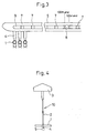
- This fastener 10 for example as shown in Fig. 5, a plurality of fasteners 10 are formed on a structure 11 so that they are linked and mutually parallel to one another, after which, for example as shown in Fig. 6, a special fastener attaching apparatus 30, that is, a gun is used to poke and pass the individual fasteners 10 as they are cut away from the above-noted fastener structure 11, thereby attaching them to a prescribed product or object.
- a special fastener attaching apparatus 30 that is, a gun is used to poke and pass the individual fasteners 10 as they are cut away from the above-noted fastener structure 11, thereby attaching them to a prescribed product or object.
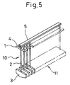
- a fastener structure 11 that is provided at the upper surface of the above-noted fastener attaching apparatus 30 is inserted through a supply aperture 32 of a supply part 31 thereof, so that, as shown for example in Fig. 6, a trigger part 16 can be operated, the result being that individual fasteners 10 that are separated away from the fastener structure 11 are inserted into a hollow needle 12, after which they are ejected from an end of the hollow needle that protrudes from the opposite side of a product or object, thereby attaching the fastener 10 to the product or object.
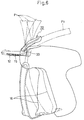
- the filament 2 of the fastener 10 is guided into the product or object via a slit 33 that is provided in the fastener attaching apparatus 30 and a slit 15 that is provide at the side of the hollow needle 12.
- the fastener structure 11 is mounted at the upper supply aperture 31 of the fastener attaching apparatus 30, the operation will be performed with a long section of the fastener structure 11 upright in an approximately perpendicular attitude with respect to the fastener attaching apparatus 30 at the upper supply aperture 31 thereof, the result being that the fastener structure 11 not only flops around, making the above-noted operation difficult, but also in many cases can come into contact with other products or objects, can also come into contact with the operator's hand or fingers, can cause damage to products and injury to the operator, thereby not only lowering product quality, but also reducing the working efficiency in order to prevent such risks as noted above.
- a method has been developed to limit the long protrusion of the fastener structure 30 from the top of the fastener attaching apparatus, to provide stable supply of the fastener structure 11, and to improve work efficiency and prevent work accidents, this method being on of providing a limiting guide 22 for the fastener structure 11 in the region of the fastener structure supply aperture 31 of the fastener attaching apparatus 30, this acting to deform the shape of the feed path of the fastener structure 11, for example so as to be a curve as indicated by P2 in Fig. 6.
- the present invention has the following basic technical constitution.
- the present invention is a structure that is a collection of a plurality of fasteners, each of which comprises a head part, a filament that is connected to the head part, and a crossbar that is provided on the end of the filament opposite from the end that is connected to the head part, and which is approximately perpendicular to the filament, wherein each of the fasteners is connected to a common linear support element, via a linking section that is an extension that crosses over the above-noted crossbar in the axial direction of the filament, so that the head parts and the crossbars of each of the fasteners are mutually parallel, a force that bends the above-noted common linear support element along a plane formed by a group of filaments being smaller than a force that bends the fastener structure in another direction.
- the fastener structure of the present invention is provided with a plurality of apertures intermittently in the longitudinal direction of the common linear support element.
- a fastener structure according to the present invention can easily be bent in a direction of the arrangement of the fasteners and, as a result, can be easily manufactured in a long configuration suitable for, and used with, a specific limiting guide 22, as shown in Fig. 6.
- FIG. 1 is a perspective view of an example of a fastener structure 10 according to the present invention
- this drawing shows a structure 11 that is formed as a collection of a plurality of fasteners 10, this fastener comprising a head part 3, a filament 2 that is connected to the head part 3, and a crossbar 1 that is provided on the end of the filament 2 that is opposite the end thereof which is connected to the head 3 and which is approximately perpendicular to the filament 2.
- Each of these structures 10 is connected to a common linear support element 5, via a linking section 4 that is an extension that crosses over the above-noted crossbar 1 in the axial direction of the filament, so that the head parts 3 and the crossbars 1 of each of the fasteners 10 are mutually parallel, a force that bends the above-noted common linear support element 5 along a plane S formed by a group of filaments 2 being smaller than a force that bends the fastener structure 11 in another direction.
- the common linear support element 5 be configured so as to enable it to be easily bent in the direction indicated above but so that, in other directions, such as the direction D1 or the direction D2 that are indicated in Fig. 9, it is difficult to bend.
- the common linear support element 5 in a fastener structure 11 according to the present invention have a cross-section which has a length in the direction that coincides with the axial direction of the filament 2 that is greater than the length in the direction that is perpendicular to the filament, that is, the direction that of the crossbar 4.
- the cross-section of the common linear support element 5 is configured so that length L1 as shown in Fig. 2, which coincides with the axial direction of the filament 2, is greater than the length L2, which coincides with the direction of the crossbar 4.
- the present invention does not impose any particular restriction with regard to the shape of the head 3 and, while a shape having some degree of surface area such as shown in Fig. 1 is preferable, it is also possible to have a head that has a shape similar to that of the crossbar 4.
- the common linear support element 5 of the present invention as shown in Fig. 3, be provided with apertures 7, these being provided intermittently along the longitudinal direction thereof.
- This configuration not only makes the common linear support element 5 more flexible, but also contributes to a reduction in weight, a reduction in raw materials used, and a reduction in cost.
- the common linear support element 5 have at least on one side thereof a groove 9 along the longitudinal direction thereof.
- This configuration in addition to imparting flexibility to the common linear support element 5, contributes to a reduction in weight, a reduction in raw materials used, and a reduction in cost, and also makes it possible to maintain the strength required to resist bending in the direction shown in Fig. 9.
- some aperture 8 of the above-noted plurality of apertures 7 is of a different shape than the apertures 7.
- the shape of the aperture 8, the size thereof, and the arrangement ratio thereof with respect to the other apertures 7 can be arbitrarily established.
- the fastener structure 11 according to the present invention be formed as one piece from a synthetic resin material such as nylon or polypropylene.
- the fastener structure according to the present invention even in the case in which this structure is long, can be used with a fastener attaching apparatus 30 as used in the past to perform highly safe attachment.
Landscapes
- Physics & Mathematics (AREA)
- General Physics & Mathematics (AREA)
- Engineering & Computer Science (AREA)
- Theoretical Computer Science (AREA)
- Labeling Devices (AREA)
- Slide Fasteners, Snap Fasteners, And Hook Fasteners (AREA)
- Mutual Connection Of Rods And Tubes (AREA)
Abstract
Description
- The present invention relates to a fastener structure, and more particularly to a fastener that is used for the purpose of affixing various labels, including tags indicating brand names, material, method of handling or price, to objects such as clothing, sundry items, footwear, socks and bags, clothes hangers, display shelves, and product display apparatuses, and to fastener that is used to bundle together a number of items of clothing or sundry items as one group of products, and to a fastener structure for supplying the above-noted fastener.
- In the past, one means of attaching a label or tag to a product or bundling a number of products together was the
fastener 10 as shown in Fig. 8. - The
fastener 10, as shown in Fig. 8, comprises ahead part 3, afilament 2 that is connected to thehead part 3, and acrossbar 1, which is provided on the end of thefilament 2 opposite from the end that is connected to thehead part 3, and which is approximately perpendicular to thefilament 2. - This fastener 10, for example as shown in Fig. 5, a plurality of
fasteners 10 are formed on astructure 11 so that they are linked and mutually parallel to one another, after which, for example as shown in Fig. 6, a special fastener attaching apparatus 30, that is, a gun is used to poke and pass theindividual fasteners 10 as they are cut away from the above-notedfastener structure 11, thereby attaching them to a prescribed product or object. - More specifically, as shown in Fig. 7, a
fastener structure 11 that is provided at the upper surface of the above-noted fastener attaching apparatus 30 is inserted through asupply aperture 32 of asupply part 31 thereof, so that, as shown for example in Fig. 6, atrigger part 16 can be operated, the result being thatindividual fasteners 10 that are separated away from thefastener structure 11 are inserted into ahollow needle 12, after which they are ejected from an end of the hollow needle that protrudes from the opposite side of a product or object, thereby attaching thefastener 10 to the product or object. - During this process, the
filament 2 of thefastener 10 is guided into the product or object via aslit 33 that is provided in the fastener attaching apparatus 30 and aslit 15 that is provide at the side of thehollow needle 12. - In using the above-noted
fastener structure 11 and fastener attaching apparatus 30 in the past to attach afastener 10 to an individual product or object, because of the small number offasteners 10 which make up thefastener structure 11 and the length of the fastener structure, which was not that great, when performing the operation of attaching the above-notedfastener 10, the operation is performed with thefastener structure 11, as shown by P1 in Fig. 6, standing upright from theupper supply aperture 31 of the fastener attaching apparatus 30, in an approximate perpendicular attitude thereto. - However, to achieve the object of improving the efficiency of the above-described operation, recent years have seen an increase in the number of
fasteners 10 that make up thefastener structure 11, which has resulted in afastener structure 11 of great length. - If the above-noted operation is performed under the above-noted conditions, if the
fastener structure 11 is mounted at theupper supply aperture 31 of the fastener attaching apparatus 30, the operation will be performed with a long section of thefastener structure 11 upright in an approximately perpendicular attitude with respect to the fastener attaching apparatus 30 at theupper supply aperture 31 thereof, the result being that thefastener structure 11 not only flops around, making the above-noted operation difficult, but also in many cases can come into contact with other products or objects, can also come into contact with the operator's hand or fingers, can cause damage to products and injury to the operator, thereby not only lowering product quality, but also reducing the working efficiency in order to prevent such risks as noted above. - For the above-noted reason, as shown in Fig. 6, a method has been developed to limit the long protrusion of the fastener structure 30 from the top of the fastener attaching apparatus, to provide stable supply of the
fastener structure 11, and to improve work efficiency and prevent work accidents, this method being on of providing alimiting guide 22 for thefastener structure 11 in the region of the fastenerstructure supply aperture 31 of the fastener attaching apparatus 30, this acting to deform the shape of the feed path of thefastener structure 11, for example so as to be a curve as indicated by P2 in Fig. 6. - In the past, however, because the
fastener structure 11 was designed with the understanding that it would protrude approximately perpendicularly from the fastener attaching apparatus 30, that is, in the direction indicated as P1 in Fig. 6, it was formed so as to rigid, making it difficult to bend it in the curve indicated as P2 in Fig. 6. - Therefore, if a
fastener structure 11 of the past were to be forcibly bent to a curved shape such as indicated as P2 in Fig. 6, because of the excessive load that would be placed on the configuration of the fastener structure, there was the problem of damaging the fastener attaching apparatus 30. - For the above-noted reason, in the past it was only practical to use a
short fastener structure 11 or, stated differently, to use afastener structure 11 that does not havemany fasteners 10, this resulting in a worsening of efficiency and an increase in cost. - Accordingly, it is an object of the present invention to provide a fastener structure that overcomes the above-noted drawbacks of the prior art, and one which, even if the length of the
fastener structure 11 becomes great, it is possible to use a fastener attaching apparatus of the past to achieve highly safe attachment of the fasteners. - In order to achieve the above-noted object, the present invention has the following basic technical constitution. Specifically, the present invention is a structure that is a collection of a plurality of fasteners, each of which comprises a head part, a filament that is connected to the head part, and a crossbar that is provided on the end of the filament opposite from the end that is connected to the head part, and which is approximately perpendicular to the filament, wherein each of the fasteners is connected to a common linear support element, via a linking section that is an extension that crosses over the above-noted crossbar in the axial direction of the filament, so that the head parts and the crossbars of each of the fasteners are mutually parallel, a force that bends the above-noted common linear support element along a plane formed by a group of filaments being smaller than a force that bends the fastener structure in another direction.
- And more specifically, the fastener structure of the present invention is provided with a plurality of apertures intermittently in the longitudinal direction of the common linear support element.
- By adopting the above-described technical constitution, a fastener structure according to the present invention can easily be bent in a direction of the arrangement of the fasteners and, as a result, can be easily manufactured in a long configuration suitable for, and used with, a specific
limiting guide 22, as shown in Fig. 6. -
- Fig. 1 is a perspective view that shows the configuration of a specific example of fastener structure according to the present invention.
- Fig. 2 is a side view that shows an example of the configuration of a common linear support element of a fastener structure according to the present invention.
- Fig. 3 is a cross-sectional view that shows an example of the configuration of a common linear support element of a fastener structure according to the present invention.
- Fig. 4 is a drawing that shows a specific example of the configuration of a fastener of the past.
- Fig. 5 is a drawing that shows an specific example of the configuration of a fastener structure of the past.
- Fig. 6 is a plan view that shows the configuration of a specific example of a fastener attaching apparatus of the past.
- Fig. 7 is a plan view that shows a specific example of the structure of the fastener supply part of a fastener attaching apparatus of the past.
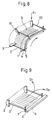
- Fig. 8 is a perspective view that illustrates an example of the case of bending a fastener structure according to the present invention into a curve.
- Fig. 9 is a perspective view that shows the direction in which it is difficult to bend the fastener structure according to the present invention.
-
- Preferred embodiments of the present invention will be described in detail below, with reference being made to relevant accompanying drawings.
- Specifically, referring to Fig. 1, which is a perspective view of an example of a
fastener structure 10 according to the present invention, this drawing shows astructure 11 that is formed as a collection of a plurality offasteners 10, this fastener comprising ahead part 3, afilament 2 that is connected to thehead part 3, and acrossbar 1 that is provided on the end of thefilament 2 that is opposite the end thereof which is connected to thehead 3 and which is approximately perpendicular to thefilament 2. Each of thesestructures 10 is connected to a commonlinear support element 5, via a linkingsection 4 that is an extension that crosses over the above-notedcrossbar 1 in the axial direction of the filament, so that thehead parts 3 and thecrossbars 1 of each of thefasteners 10 are mutually parallel, a force that bends the above-noted commonlinear support element 5 along a plane S formed by a group offilaments 2 being smaller than a force that bends thefastener structure 11 in another direction. - That is, in contrast to a
fastener structure 11 of the past, wherein the commonlinear support element 5, as shown in Fig. 5, was formed so as to be quite thick, a result being that it was impossible bend the commonlinear support element 5 along the plane S formed by a large number of filaments, in the case of thefastener structure 11 according to the present invention, as shown in Fig. 8, it is possible to easily bend the commonlinear support element 5 along theplane 8 that is formed by a group offilaments 2. - That is, as shown in Fig. 8, if one end of the
fastener structure 11 is fixed to a holding part so that the filaments are parallel, and an appropriate force F1 is applied to the other end of thefastener structure 11 perpendicularly to this plane S, it is possible to easily bend the commonlinear support element 5 as shown in Fig. 8. - For this reason, it is desirable that, in a
fastener structure 11 according to the present invention the commonlinear support element 5 be configured so as to enable it to be easily bent in the direction indicated above but so that, in other directions, such as the direction D1 or the direction D2 that are indicated in Fig. 9, it is difficult to bend. - Specifically, it is desirable that the common
linear support element 5 in afastener structure 11 according to the present invention have a cross-section which has a length in the direction that coincides with the axial direction of thefilament 2 that is greater than the length in the direction that is perpendicular to the filament, that is, the direction that of thecrossbar 4. - That is, the cross-section of the common
linear support element 5 is configured so that length L1 as shown in Fig. 2, which coincides with the axial direction of thefilament 2, is greater than the length L2, which coincides with the direction of thecrossbar 4. - The present invention does not impose any particular restriction with regard to the shape of the
head 3 and, while a shape having some degree of surface area such as shown in Fig. 1 is preferable, it is also possible to have a head that has a shape similar to that of thecrossbar 4. - It is desirable that the common
linear support element 5 of the present invention, as shown in Fig. 3, be provided withapertures 7, these being provided intermittently along the longitudinal direction thereof. - This configuration not only makes the common
linear support element 5 more flexible, but also contributes to a reduction in weight, a reduction in raw materials used, and a reduction in cost. - There are no particular restrictions placed on the aperture surface of the
aperture 7, the number of these apertures, and the interval of the apertures, these being establishable as appropriate. - Additionally, in a
fastener structure 11 according to the present invention, it is also desirable that the commonlinear support element 5 have at least on one side thereof agroove 9 along the longitudinal direction thereof. - This configuration, in addition to imparting flexibility to the common
linear support element 5, contributes to a reduction in weight, a reduction in raw materials used, and a reduction in cost, and also makes it possible to maintain the strength required to resist bending in the direction shown in Fig. 9. - Furthermore, in the present invention, it is possible for some
aperture 8 of the above-noted plurality ofapertures 7 to be of a different shape than theapertures 7. - There is no particular specification of a condition for mixing apertures having a different shape at a prescribed interval wit other apertures.
- That is, the shape of the
aperture 8, the size thereof, and the arrangement ratio thereof with respect to theother apertures 7 can be arbitrarily established. - For example, as shown in Fig. 3, it is possible after a prescribed number of
continuous apertures 7 of a rectangular shape, to have oneround aperture 8, after which there is a prescribed number ofrectangular apertures 7, in which case the position of theaperture 8 can be established in accordance with the number offasteners 10. - That is, by inserting an
aperture 8 every 100apertures 7, if onefastener structure 11 includes 300fasteners 10, if a user uses thefasteners 10 in units of 100, this can be used as a guide in dividing up thefastener structure 11 into these units. - It is desirable that the
fastener structure 11 according to the present invention be formed as one piece from a synthetic resin material such as nylon or polypropylene. - By virtue of the above-noted technical constitution, the fastener structure according to the present invention, even in the case in which this structure is long, can be used with a fastener attaching apparatus 30 as used in the past to perform highly safe attachment.
Claims (5)
- A structure comprising a collection of a plurality of fasteners, each said fastener comprising a head part, a filament that is connected to said head part, and a crossbar that is provided on an end of said filament that is opposite from the end that is connected to said head, and that is approximately perpendicular to said filament, wherein each of said fasteners is connected to a common linear support element, via a linking section that is an extension that crosses over said crossbar in the axial direction of said filament, so that said head parts and said crossbars of each of said fasteners are mutually parallel, a force that bends said common linear support element along a plane formed by a group of said filaments being smaller than a force that bends said fastener structure in another direction and wherein said common linear support element further characterizing in that said common linear support element being formed in it a plurality of apertures intermittently in the longitudinal direction thereof.
- A fastener structure according to claim 1, wherein said common linear support element has formed in it a groove along the longitudinal direction thereof.
- A fastener structure according to claim 1, wherein part of said plurality of apertures has a shape that differs from the other apertures.
- A fastener structure according to any one of claims 1 to 3, wherein said common linear support element has a cross-section having a length in a direction that coincides with the axial direction of said filament that is greater than a length that is perpendicular to said filament.
- A fastener structure according to claim 4, wherein said fastener structure is fabricated as one unit from synthetic resin material.
Applications Claiming Priority (3)
| Application Number | Priority Date | Filing Date | Title |
|---|---|---|---|
| JP30675897A JP4059551B2 (en) | 1997-11-10 | 1997-11-10 | Locking piece structure |
| JP306758/97 | 1997-11-10 | ||
| JP30675897 | 1997-11-10 |
Publications (3)
| Publication Number | Publication Date |
|---|---|
| EP0915449A2 true EP0915449A2 (en) | 1999-05-12 |
| EP0915449A3 EP0915449A3 (en) | 2000-08-02 |
| EP0915449B1 EP0915449B1 (en) | 2004-05-06 |
Family
ID=17960956
Family Applications (1)
| Application Number | Title | Priority Date | Filing Date |
|---|---|---|---|
| EP98120972A Expired - Lifetime EP0915449B1 (en) | 1997-11-10 | 1998-11-05 | Fastener structure |
Country Status (4)
| Country | Link |
|---|---|
| US (1) | US6062384A (en) |
| EP (1) | EP0915449B1 (en) |
| JP (1) | JP4059551B2 (en) |
| DE (1) | DE69823612T2 (en) |
Cited By (2)
| Publication number | Priority date | Publication date | Assignee | Title |
|---|---|---|---|---|
| EP1112938A1 (en) * | 1999-11-10 | 2001-07-04 | Kotec's Co. Ltd. | Apparatus for attaching tag pins |
| EP1659066A3 (en) * | 2004-11-12 | 2006-07-26 | Kotec's Co., Ltd. | Device for use with a tag attaching apparatus |
Families Citing this family (11)
| Publication number | Priority date | Publication date | Assignee | Title |
|---|---|---|---|---|
| GB0208288D0 (en) * | 2002-04-10 | 2002-05-22 | Lyon Arthur C | Attachment |
| US7147374B2 (en) * | 2002-12-26 | 2006-12-12 | Ajootian Janice K | Combination cosmetic purse and display package |
| US7654618B2 (en) * | 2005-04-08 | 2010-02-02 | Tk Holdings Inc. | Webbing tack |
| US20080235918A1 (en) * | 2007-04-02 | 2008-10-02 | Laura Mooney | Fastener |
| EP2301851A1 (en) | 2008-05-28 | 2011-03-30 | M.I.T. International Co., Ltd. | Locking piece fixing device |
| US20120279023A1 (en) * | 2011-05-06 | 2012-11-08 | Avery Dennison Corporation | Plastic Fastening Device Comprising a Recycled Thermoplastic Resin |
| USD738712S1 (en) * | 2012-11-29 | 2015-09-15 | Avery Dennison Corporation | Notched fastener strip |
| USD836426S1 (en) * | 2017-01-04 | 2018-12-25 | Avery Dennison Corporation | Fastener |
| USD835502S1 (en) * | 2017-01-04 | 2018-12-11 | Avery Dennison Corporation | Fastener |
| USD835501S1 (en) * | 2017-01-04 | 2018-12-11 | Avery Dennison Corporation | Fastener |
| USD835500S1 (en) * | 2017-01-04 | 2018-12-11 | Avery Dennison Corporation | Fastener |
Citations (4)
| Publication number | Priority date | Publication date | Assignee | Title |
|---|---|---|---|---|
| CH598058A5 (en) * | 1976-09-09 | 1978-04-28 | Japan Banok Co Ltd | Moulded synthetic material resin tag pin |
| US4417682A (en) * | 1980-10-24 | 1983-11-29 | Japan Bano'k Co., Ltd. | Tag attaching machine |
| US4664306A (en) * | 1986-04-22 | 1987-05-12 | Kwik Ticket, Inc. | Tag attacher |
| US5405070A (en) * | 1993-01-29 | 1995-04-11 | Kunreuther; Steven | Clip of attachments |
Family Cites Families (5)
| Publication number | Priority date | Publication date | Assignee | Title |
|---|---|---|---|---|
| US32332A (en) * | 1861-05-14 | Improvement in electro-magnetic bathing apparatus | ||
| NL6710444A (en) * | 1967-07-28 | 1969-01-30 | ||
| US4712677A (en) * | 1977-08-24 | 1987-12-15 | Dennison Manufacturing Company | Method and apparatus for dispensing fasteners |
| US4456123A (en) * | 1979-08-31 | 1984-06-26 | Dennison Manufacturing Company | Method and apparatus for dispensing fasteners |
| US5110638A (en) * | 1990-03-20 | 1992-05-05 | Raychem Corporation | Marker device with permanent indicia |
-
1997
- 1997-11-10 JP JP30675897A patent/JP4059551B2/en not_active Expired - Fee Related
-
1998
- 1998-11-05 EP EP98120972A patent/EP0915449B1/en not_active Expired - Lifetime
- 1998-11-05 DE DE69823612T patent/DE69823612T2/en not_active Expired - Fee Related
- 1998-11-06 US US09/187,260 patent/US6062384A/en not_active Expired - Fee Related
Patent Citations (4)
| Publication number | Priority date | Publication date | Assignee | Title |
|---|---|---|---|---|
| CH598058A5 (en) * | 1976-09-09 | 1978-04-28 | Japan Banok Co Ltd | Moulded synthetic material resin tag pin |
| US4417682A (en) * | 1980-10-24 | 1983-11-29 | Japan Bano'k Co., Ltd. | Tag attaching machine |
| US4664306A (en) * | 1986-04-22 | 1987-05-12 | Kwik Ticket, Inc. | Tag attacher |
| US5405070A (en) * | 1993-01-29 | 1995-04-11 | Kunreuther; Steven | Clip of attachments |
Cited By (3)
| Publication number | Priority date | Publication date | Assignee | Title |
|---|---|---|---|---|
| EP1112938A1 (en) * | 1999-11-10 | 2001-07-04 | Kotec's Co. Ltd. | Apparatus for attaching tag pins |
| EP1659066A3 (en) * | 2004-11-12 | 2006-07-26 | Kotec's Co., Ltd. | Device for use with a tag attaching apparatus |
| US7380694B2 (en) | 2004-11-12 | 2008-06-03 | Kotec's Co., Ltd. | Attachment to be used for an apparatus for attaching a tag-attaching pin |
Also Published As
| Publication number | Publication date |
|---|---|
| EP0915449A3 (en) | 2000-08-02 |
| JP4059551B2 (en) | 2008-03-12 |
| DE69823612T2 (en) | 2005-04-21 |
| US6062384A (en) | 2000-05-16 |
| JPH11143367A (en) | 1999-05-28 |
| DE69823612D1 (en) | 2004-06-09 |
| EP0915449B1 (en) | 2004-05-06 |
Similar Documents
| Publication | Publication Date | Title |
|---|---|---|
| EP0915449B1 (en) | Fastener structure | |
| AU701131B2 (en) | Button fastener and clip | |
| GB2270713A (en) | Tag fastener | |
| EP0608610A1 (en) | Improved clip of attachments | |
| US9193492B2 (en) | Method of applying notched fastener stock | |
| US6561350B1 (en) | Sticking device | |
| US3924298A (en) | Attachment and mounting construction | |
| CA2337769C (en) | Fastener clip | |
| EP0903715A2 (en) | Label supporting means | |
| US6732899B2 (en) | System for dispensing plastic fasteners | |
| US20030164393A1 (en) | Locking element attaching device | |
| US6595360B2 (en) | Fastening element | |
| CA1048746A (en) | Attachment and mounting construction | |
| US20120159903A1 (en) | Wide filament fastener | |
| US9789991B2 (en) | Reactor plate assembly and brush anvil for use in conjunction therewith | |
| US20180178454A1 (en) | Method for coupling together a plurality of items and plastic fastener for use therewith | |
| JPH06329138A (en) | Label hanger magazine | |
| CN101107642A (en) | Tag holder with flexible thread | |
| EP1083537A2 (en) | Sealing implement | |
| US10196166B2 (en) | Method of penetrating material with a fastener dispensing needle | |
| KR200155118Y1 (en) | Loop connected attachments | |
| GB2114493A (en) | Fastener attacher | |
| JPH08156926A (en) | Tag-attaching machine | |
| NL8200513A (en) | ATTACHERS FOR CONNECTORS. | |
| JPH07291246A (en) | Label hanger magazine |
Legal Events
| Date | Code | Title | Description |
|---|---|---|---|
| PUAI | Public reference made under article 153(3) epc to a published international application that has entered the european phase |
Free format text: ORIGINAL CODE: 0009012 |
|
| AK | Designated contracting states |
Kind code of ref document: A2 Designated state(s): DE FR GB IT |
|
| AX | Request for extension of the european patent |
Free format text: AL;LT;LV;MK;RO;SI |
|
| PUAL | Search report despatched |
Free format text: ORIGINAL CODE: 0009013 |
|
| AK | Designated contracting states |
Kind code of ref document: A3 Designated state(s): AT BE CH CY DE DK ES FI FR GB GR IE IT LI LU MC NL PT SE |
|
| AX | Request for extension of the european patent |
Free format text: AL;LT;LV;MK;RO;SI |
|
| 17P | Request for examination filed |
Effective date: 20010202 |
|
| AKX | Designation fees paid |
Free format text: DE FR GB IT |
|
| GRAP | Despatch of communication of intention to grant a patent |
Free format text: ORIGINAL CODE: EPIDOSNIGR1 |
|
| RTI1 | Title (correction) |
Free format text: FASTENER STRUCTURE |
|
| GRAS | Grant fee paid |
Free format text: ORIGINAL CODE: EPIDOSNIGR3 |
|
| GRAA | (expected) grant |
Free format text: ORIGINAL CODE: 0009210 |
|
| AK | Designated contracting states |
Kind code of ref document: B1 Designated state(s): DE FR GB IT |
|
| REG | Reference to a national code |
Ref country code: GB Ref legal event code: FG4D |
|
| REF | Corresponds to: |
Ref document number: 69823612 Country of ref document: DE Date of ref document: 20040609 Kind code of ref document: P |
|
| ET | Fr: translation filed | ||
| PLBE | No opposition filed within time limit |
Free format text: ORIGINAL CODE: 0009261 |
|
| STAA | Information on the status of an ep patent application or granted ep patent |
Free format text: STATUS: NO OPPOSITION FILED WITHIN TIME LIMIT |
|
| 26N | No opposition filed |
Effective date: 20050208 |
|
| REG | Reference to a national code |
Ref country code: HK Ref legal event code: WD Ref document number: 1021055 Country of ref document: HK |
|
| PGFP | Annual fee paid to national office [announced via postgrant information from national office to epo] |
Ref country code: DE Payment date: 20071130 Year of fee payment: 10 |
|
| PGFP | Annual fee paid to national office [announced via postgrant information from national office to epo] |
Ref country code: IT Payment date: 20071022 Year of fee payment: 10 |
|
| PGFP | Annual fee paid to national office [announced via postgrant information from national office to epo] |
Ref country code: GB Payment date: 20071018 Year of fee payment: 10 Ref country code: FR Payment date: 20071011 Year of fee payment: 10 |
|
| GBPC | Gb: european patent ceased through non-payment of renewal fee |
Effective date: 20081105 |
|
| PG25 | Lapsed in a contracting state [announced via postgrant information from national office to epo] |
Ref country code: IT Free format text: LAPSE BECAUSE OF NON-PAYMENT OF DUE FEES Effective date: 20081105 |
|
| REG | Reference to a national code |
Ref country code: FR Ref legal event code: ST Effective date: 20090731 |
|
| PG25 | Lapsed in a contracting state [announced via postgrant information from national office to epo] |
Ref country code: DE Free format text: LAPSE BECAUSE OF NON-PAYMENT OF DUE FEES Effective date: 20090603 |
|
| PG25 | Lapsed in a contracting state [announced via postgrant information from national office to epo] |
Ref country code: GB Free format text: LAPSE BECAUSE OF NON-PAYMENT OF DUE FEES Effective date: 20081105 |
|
| PG25 | Lapsed in a contracting state [announced via postgrant information from national office to epo] |
Ref country code: FR Free format text: LAPSE BECAUSE OF NON-PAYMENT OF DUE FEES Effective date: 20081130 |