EP0914879A1 - Method and apparatus for automatic bending of metal sheets - Google Patents
Method and apparatus for automatic bending of metal sheets Download PDFInfo
- Publication number
- EP0914879A1 EP0914879A1 EP98119190A EP98119190A EP0914879A1 EP 0914879 A1 EP0914879 A1 EP 0914879A1 EP 98119190 A EP98119190 A EP 98119190A EP 98119190 A EP98119190 A EP 98119190A EP 0914879 A1 EP0914879 A1 EP 0914879A1
- Authority
- EP
- European Patent Office
- Prior art keywords
- manipulator
- bending
- sheet
- metal sheet
- press
- Prior art date
- Legal status (The legal status is an assumption and is not a legal conclusion. Google has not performed a legal analysis and makes no representation as to the accuracy of the status listed.)
- Granted
Links
- 238000005452 bending Methods 0.000 title claims abstract description 107
- 239000002184 metal Substances 0.000 title claims abstract description 68
- 238000000034 method Methods 0.000 title claims abstract description 14
- 230000000717 retained effect Effects 0.000 claims 2
- 238000007599 discharging Methods 0.000 claims 1
- 239000000463 material Substances 0.000 description 5
- 238000004422 calculation algorithm Methods 0.000 description 3
- 230000006870 function Effects 0.000 description 3
- 238000004364 calculation method Methods 0.000 description 2
- 238000000151 deposition Methods 0.000 description 2
- 235000004443 Ricinus communis Nutrition 0.000 description 1
- 230000008021 deposition Effects 0.000 description 1
- 238000010586 diagram Methods 0.000 description 1
- 230000000873 masking effect Effects 0.000 description 1
Images


Classifications
-
- B—PERFORMING OPERATIONS; TRANSPORTING
- B21—MECHANICAL METAL-WORKING WITHOUT ESSENTIALLY REMOVING MATERIAL; PUNCHING METAL
- B21D—WORKING OR PROCESSING OF SHEET METAL OR METAL TUBES, RODS OR PROFILES WITHOUT ESSENTIALLY REMOVING MATERIAL; PUNCHING METAL
- B21D43/00—Feeding, positioning or storing devices combined with, or arranged in, or specially adapted for use in connection with, apparatus for working or processing sheet metal, metal tubes or metal profiles; Associations therewith of cutting devices
- B21D43/02—Advancing work in relation to the stroke of the die or tool
- B21D43/026—Combination of two or more feeding devices provided for in B21D43/04 - B21D43/18
-
- B—PERFORMING OPERATIONS; TRANSPORTING
- B21—MECHANICAL METAL-WORKING WITHOUT ESSENTIALLY REMOVING MATERIAL; PUNCHING METAL
- B21D—WORKING OR PROCESSING OF SHEET METAL OR METAL TUBES, RODS OR PROFILES WITHOUT ESSENTIALLY REMOVING MATERIAL; PUNCHING METAL
- B21D43/00—Feeding, positioning or storing devices combined with, or arranged in, or specially adapted for use in connection with, apparatus for working or processing sheet metal, metal tubes or metal profiles; Associations therewith of cutting devices
- B21D43/02—Advancing work in relation to the stroke of the die or tool
- B21D43/04—Advancing work in relation to the stroke of the die or tool by means in mechanical engagement with the work
- B21D43/10—Advancing work in relation to the stroke of the die or tool by means in mechanical engagement with the work by grippers
- B21D43/105—Manipulators, i.e. mechanical arms carrying a gripper element having several degrees of freedom
-
- B—PERFORMING OPERATIONS; TRANSPORTING
- B21—MECHANICAL METAL-WORKING WITHOUT ESSENTIALLY REMOVING MATERIAL; PUNCHING METAL
- B21D—WORKING OR PROCESSING OF SHEET METAL OR METAL TUBES, RODS OR PROFILES WITHOUT ESSENTIALLY REMOVING MATERIAL; PUNCHING METAL
- B21D5/00—Bending sheet metal along straight lines, e.g. to form simple curves
- B21D5/02—Bending sheet metal along straight lines, e.g. to form simple curves on press brakes without making use of clamping means
Definitions
- the present invention relates to bending of metal sheets by a bending press having a reciprocable bending mould and more precisely it relates to a method and an apparatus for automatic bending of metal sheets having high versatility of use, particularly for the automatic bending of small metal sheets, whereby it is possible to perform a number of bends on a same sheet in extremely short spaces of time; dead times resulting on standard bending presses from the picking up operation of a metal sheet and releasing of the same after bending, are therefore eliminated.
- Apparatuses for automatic bending of metal sheet material that is to say bending presses appropriately slaved by a robot, have been variously used and proposed in some prior documents, for example in US-A-4.594.870, EP-A-O 555 908 and EP-A-O 742 054.
- All these automatic bending apparatuses generally involve the use of a single robot or automatic device to perform all the picking up operations of each sheet, bending and releasing of the same bent piece, carrying out all the bending operations during a working cycle, in a single phase by means of the single robot or manipulator.
- EP-A-O 742 054 suggests the use of a Cartesian robot having several powered axes for slaving a bending press; by means of a particular calculation algorithm the gripping member of the robot is allowed to follow the sheet during bending movements, continuously controlling the position of gripping means as a function of the movement of a mould member of the same bending press, which is continuously detected by an appropriate sensor.
- the general object of the present invention is to provide an apparatus for automatic bending of metal sheets or more generally sheet material, which is suitable for fulfilling the needs referred above.
- a further object of the present invention is to provide a method for automatic bending of sheet material by means of an apparatus which can be easily slaved to any type of press, such that the handling operations of the pieces can take place in masked conditions and without dead working times for the same press, in that the operations of picking up a sheet to be bent and of releasing the bent part can take place during the same bending cycle, with the press in operation.
- the apparatus comprises first and second independent manipulators, for example anthropomorphic robots, which are movable along a linear path, each robot having an articulated arm and a picking up member defining a number of rotational axes and control means which allow each of the two manipulators to independently move along said travelling path parallel to the front side of a bending press and to follow the various movements of a metal sheet during the bending operations, sequentially performing the steps of the entire working cycle which is divided between and sequentially performed by the two manipulators.
- first and second independent manipulators for example anthropomorphic robots, which are movable along a linear path, each robot having an articulated arm and a picking up member defining a number of rotational axes and control means which allow each of the two manipulators to independently move along said travelling path parallel to the front side of a bending press and to follow the various movements of a metal sheet during the bending operations, sequentially performing the steps of the entire working cycle which is divided between and sequentially performed by the two manipulators.
- first and second independent manipulators
- the time for picking up a sheet and for releasing a bent piece is substantially equal to the effective working cycle of the press, also in view of the fact that few bends only are normally made on sheets with small dimensions.
- the cycle for bending a sheet is performed as a single operation divided between or sequentially performed by the two manipulators, so that when the first manipulator picks up a sheet and performs part of the bending cycle, for example the first two bends, the second manipulator releases the previously bent piece and puts itself in a stand-by conditions; then the first manipulator releases the partially bent sheet clamped into the moulds of the press, after which the second manipulator, intervenes to take it and complete the bending cycle.
- the first manipulator has already picked up a new metal sheet to start a new bending cycle.
- the other one picks up a new sheet to be bent or discharges an already bent piece.
- the advantage of the present invention therefore resided in the fact that it makes possible to mask into the working cycle of the press the handling steps for picking up and releasing the pieces, thanks to the alternating and combined use of the two manipulators, co-related to the working cycle of the bending press.
- the apparatus according to the invention is totally independent of the type of machine to be used for bending, which can be either of manual or automatic type, in this way achieving high working flexibility.
- the first manipulator picks up a metal sheet and makes the first half of the bends.
- the first manipulator similarly to what has been referred previously, releases the partially bent piece clamped between the moulds of the press in order to pick up a new sheet, while the second manipulator takes the previous sheet which is already partially bent, clamped between the two moulds of the press.
- the completion of bending of the previous sheet by the second manipulator can therefore take place simultaneously to the start of the bending for the new sheet by the first manipulator.
- the two manipulators perform the same bending operations, simultaneously on two different sheets in different working positions of the same press.
- the apparatus substantially comprises a bending press 10 as well as a robotised device 11 for picking up and manipulating the metal sheets which are to be bent according to a programmed bending scheme.
- the bending press 10 can be of any conventional type, for example it can consist of a hydraulic press having a frame structure 12 for supporting a lower mould member 13 and respectively an upper mould member 14 vertically reciprocable in respect to the fixed mould member 13, for example by means of a pair of hydraulic cylinders 15.
- the press 10 is of the type comprising an upper movable mould member; however it may also be of the type having a lower movable mould member, or with both mould members which are moving relatively one in relation to the other.
- Reference 16 in Figure 3 denotes a front sensor for the positioning of a metal sheet between the mould members of the press, which together with side sensors supply control signals indicative of the presence and correct positioning of the metal sheet between the mould members 13 and 14. In this way a control signal is provided for the starting of each bending operation, as explained hereinbelow.
- Reference 17 in Figure 3 finally denotes a signal generator, of the linear and absolute type, directly or indirectly interlocked to the movable mould member 14 to supply reference signals indicative of the positions reached by the same movable mould member 14 during its forward movement towards the lower mould member 13, to allow a correct performance of each bending operation of a sheet.
- the robotised device 11 for picking up and manipulating metal sheets to be bent in a bending press substantially comprises a base frame 18 for supporting a first manipulator or robotised arm 19, as well as a second manipulator 20, the twin or wholly identical to the previous one.
- the manipulators 19 and 20 can slide or move parallel to the front side of the bending press 10, on a pair of tracks or guides 21 which parallely extend above the longitudinal sides of the support base 18.
- the support base 18 is also provided with pivotable or castor wheels 22 which allow its movement and correct positioning in relation to the press 10.
- a bridge frame 23 extends upwards from the base 18 to support an electronic equipment for controlling the two manipulators 19 and 20, whose operation is slaved to the press 10 in the manner described hereinunder.
- Each manipulator for example the manipulator 19, comprises in turn a base body 24 provided with wheels or runners 25 moving along the guides 21.
- the lateral movement of each manipulator 19 and 20 can be achieved by any suitable drive means, for example of the hydraulic, pneumatic or electric type.
- an electric motor 26 is provided for a pair of cogged wheels 27, each of which engages with a cogged belt 28 stretched between two cross members 29 at the ends of the support base 18.
- Each manipulator 19 and 20 also comprises a articulated arm 30 provided with a gripping member 31 which can be moved on four polar rotational axes. More particularly the articulated arm 30 comprises a first arm portion 30A capable of rotating around a horizontal axis 32 parallel to the guides 21, under the control of a first drive motor 33.
- the articulated arm 30 also comprises a second arm portion 30B capable of rotating around a second horizontal axis 34, parallel to the previous one, under the control of a second drive motor 35.
- the gripping member 31 is provided with two drive motors 31' and 31'' to rotate on two axes orthogonal one to the other, of which one is parallel to the axes 32-34 and the other one longitudinal to the same gripping member 31.
- the various motors for driving the two manipulators are also fitted with respective encoders or signal generators for providing reference signals which at all times give information on the exact position in space of the gripping member 31.
- reference 36 in Figure 2 denotes the position for loading or picking up of the metal sheets to be bent, while 37 denotes the unloading or releasing position for the bent pieces.
- the working area of the two manipulators 19 and 20 can be any one along and on both sides of the support base 18 in that physically the articulated arm 30 of each manipulator can pick up and release the metal sheets alongside the press 10, or it can use a zone to the rear of the base 18 by simple rotation in a vertical plane of the articulated arm.
- the manipulators 19 and 20 can therefore work easily both on the front side and on the rear one, according to the space available.
- FIG. 4 of the accompanying drawings shows schematically the electronic device for the control and slaving of the two manipulators 19 and 20 to the bending press 10.
- the electronic control device comprises a microprocessor 40 having a volatile memory, for example a RAM, wherein a program may be stored for controlling and slaving the two manipulators 19 and 20 to the movements of the movable mould member of the press 10, by means of the position signals supplied to the microprocessor 40 by the sensor 17 via a digital-analogic converter 41.
- a program may be stored for controlling and slaving the two manipulators 19 and 20 to the movements of the movable mould member of the press 10, by means of the position signals supplied to the microprocessor 40 by the sensor 17 via a digital-analogic converter 41.
- Program and calculation means are also provided comprising an appropriate algorithm or mathematical formula for computing the co-ordinates of the translation and rotational movements of the gripping member 31 of each manipulator, in accordance with the movement of the metal sheet during bending into the press.
- the algorithm is stored in a permanent memory 42, for example an EPROM, connected to the microprocessor 40 via the bus 43.
- reference 44 denotes a further programmable and erasable memory, for example an EEPROM wherein some variable calculation data are programmed and/or stored, such as for example the maximum width of the bending cavity of the mould member 13 and the zero point on the Z axis of the movable mould member 14, on the basis of which the microprocessor 40 will calculate the co-ordinates of movement of the gripping member 31 for the metal sheets to be bent. All this is known and explained in greater detail in the application EP-A-O 742 054 mentioned previously.
- the apparatus comprises a bending press 10 and a robotised device 11 for picking up and manipulating metal sheets to be bent, which is slaved to the press itself.
- the robotised device is formed by two independent manipulators or robots 19 and 20, between which the entire bending cycle of a sheet is divided so that the first manipulator 19 picks up a metal sheet 50 from a stack in the loading position 36 at one end of the support and guide structure 18, while the other manipulator 20 is at a standstill facing the press 10 in a waiting or stand-by condition ( Figure 5).
- the first manipulator 19 Having completed the first bending steps for the sheet 50 by means of the first manipulator 19, the latter releases the partially bent sheet 50 which is left clamped between the closed mould members 13 and 14 of the press.
- the second manipulator 20 moves towards the bent sheet clamped by the bending mould members and in the brief instant for clamping of the partially bent sheet by said second manipulator 20, the first manipulator 19 moves again to the left ( Figure 7) into the picking up position to pick up a new metal sheet 51, while the second manipulator 20, which was already ready, is slaved to the press 10 and moves its articulated arm towards the metal sheet 50, already partially bent, taking it with its gripping member in the correct position, after which the same manipulator 20 returns to the previous working position ( Figure 8) where it completes the cycle of bending of the sheet 50 as a function of the programmed work program.
- the first manipulator 19 has already taken from the stack the new metal sheet 51 to be bent, in turn adopting a waiting or stand-by condition.
- the manipulator 20 moves completely to the right in Figure 9, where it rotates at the rear its articulated arm 30 to release and deposit the bent metal sheet or piece 50 in the unloading zone 37.
- the first manipulator 19 is slaved again to the press 10 in order to position the new metal sheet 51 between the mould members 13 and 14 of the press and to perform once again a first part of the working cycle, for the new sheet, while the previous finished piece is deposited by the second manipulator in the unloading zone 37.
- the working cycle of the entire apparatus can thus be cyclically repeated and continue in the manner described above.
- the great advantage of the apparatus and method according to the invention is therefore linked to the alternate use of the two manipulators 19 and 20 in sequentially performing two different parts of the bending cycle on a same metal sheet and in performing a picking up and a releasing of a metal sheet or bent piece by one of the two manipulators while the other one is working; this allows masking of the so-called handling steps of the sheets, that is to say the picking-up of a sheet to be bent, and the releasing and deposition of a bent piece, drastically reducing working times, in particular for small metal sheets.
- the apparatus as described hitherto, can be used for bending both asymmetrical and symmetrical pieces.
- the apparatus allows the two manipulators to be simultaneously used to conjointly perform the two separated parts of the bending cycle on separate sheets.
- the first manipulator 19 picks up a metal sheet from the stack in the zone 36 and performs the first half of the bends on it. Subsequently, as in the previous bending cycle, the manipulator 19 releases the partially bent sheet clamped in the press in order to pick up a new sheet. In the meantime the second manipulator moves in the position, takes the first partially bent sheet still clamped between the mould members of the press and completes its bending. Given the symmetry of the piece to be made, this latter operation can take place simultaneously with the bending of the new metal sheet taken from the first manipulator.
Landscapes
- Engineering & Computer Science (AREA)
- Mechanical Engineering (AREA)
- Bending Of Plates, Rods, And Pipes (AREA)
- Folding Of Thin Sheet-Like Materials, Special Discharging Devices, And Others (AREA)
Abstract
Description
- The present invention relates to bending of metal sheets by a bending press having a reciprocable bending mould and more precisely it relates to a method and an apparatus for automatic bending of metal sheets having high versatility of use, particularly for the automatic bending of small metal sheets, whereby it is possible to perform a number of bends on a same sheet in extremely short spaces of time; dead times resulting on standard bending presses from the picking up operation of a metal sheet and releasing of the same after bending, are therefore eliminated.
- Apparatuses for automatic bending of metal sheet material, that is to say bending presses appropriately slaved by a robot, have been variously used and proposed in some prior documents, for example in US-A-4.594.870, EP-A-O 555 908 and EP-A-O 742 054.
- All these automatic bending apparatuses generally involve the use of a single robot or automatic device to perform all the picking up operations of each sheet, bending and releasing of the same bent piece, carrying out all the bending operations during a working cycle, in a single phase by means of the single robot or manipulator.
- More particularly EP-A-O 742 054, of the same Applicant, suggests the use of a Cartesian robot having several powered axes for slaving a bending press; by means of a particular calculation algorithm the gripping member of the robot is allowed to follow the sheet during bending movements, continuously controlling the position of gripping means as a function of the movement of a mould member of the same bending press, which is continuously detected by an appropriate sensor.
- However the robots or apparatuses of the known type allow sheets of comparatively high weight and large size only to be worked, reaching a limit for small sheets, for example with dimensions of a few hundred millimetres or slightly larger, up to pieces having a gripping edge of about 50 mm.
- Therefore, when bending a sheet material small in size, manual operations are usually required in that the use of a conventional robot or automatic bending apparatus would be disadvantageous as regards the total cycle time. Indeed the operations for handling the piece, in particular for picking up the metal sheet and releasing the same bent piece, would require overall a comparatively longer time than that which is required for performing solely the bending operations, with consequent long dead times for the press at the picking up of a new sheet and releasing of the bent piece.
- Research especially carried out has shown that there is the need to fulfil a very widespread market demand in bending pieces of small dimensions, little considered previously, and to provide automatic bending apparatuses which represent a valid economical alternative to the manual use of a bending press and to a conventional robot.
- Therefore the general object of the present invention is to provide an apparatus for automatic bending of metal sheets or more generally sheet material, which is suitable for fulfilling the needs referred above.
- A further object of the present invention is to provide a method for automatic bending of sheet material by means of an apparatus which can be easily slaved to any type of press, such that the handling operations of the pieces can take place in masked conditions and without dead working times for the same press, in that the operations of picking up a sheet to be bent and of releasing the bent part can take place during the same bending cycle, with the press in operation.
- The above can be achieved by means of a method for automatic bending of sheet material according to
claim 1, and respectively by means of automatic apparatus according to claim 5. - According to the invention, the apparatus comprises first and second independent manipulators, for example anthropomorphic robots, which are movable along a linear path, each robot having an articulated arm and a picking up member defining a number of rotational axes and control means which allow each of the two manipulators to independently move along said travelling path parallel to the front side of a bending press and to follow the various movements of a metal sheet during the bending operations, sequentially performing the steps of the entire working cycle which is divided between and sequentially performed by the two manipulators.
- As referred previously, in bending panels or metal sheets which are small in size, the time for picking up a sheet and for releasing a bent piece is substantially equal to the effective working cycle of the press, also in view of the fact that few bends only are normally made on sheets with small dimensions.
- Thanks to the use of two independent and selectively operable manipulators having integrated working cycles, appropriately slaved to a single bending press, the time for picking up and releasing a piece is masked, so that the bending press is always maintained in a bending condition; dead times are so avoided.
- According to the basic feature of the present invention the cycle for bending a sheet is performed as a single operation divided between or sequentially performed by the two manipulators, so that when the first manipulator picks up a sheet and performs part of the bending cycle, for example the first two bends, the second manipulator releases the previously bent piece and puts itself in a stand-by conditions; then the first manipulator releases the partially bent sheet clamped into the moulds of the press, after which the second manipulator, intervenes to take it and complete the bending cycle.
- Once the bending cycle has ended and the second manipulator is unloading the bent piece, the first manipulator has already picked up a new metal sheet to start a new bending cycle. In brief, according to an aspect of the present invention, while one of the manipulators is working to make some bends, the other one picks up a new sheet to be bent or discharges an already bent piece.
- The advantage of the present invention therefore resided in the fact that it makes possible to mask into the working cycle of the press the handling steps for picking up and releasing the pieces, thanks to the alternating and combined use of the two manipulators, co-related to the working cycle of the bending press.
- The apparatus according to the invention is totally independent of the type of machine to be used for bending, which can be either of manual or automatic type, in this way achieving high working flexibility.
- According to another aspect of the invention it is possible to use the two robotised arms simultaneously, for conjointly bending two separated sheets, to make perfectly symmetrical pieces.
- This can be achieved in that at the starting the first manipulator picks up a metal sheet and makes the first half of the bends. At this point the first manipulator, similarly to what has been referred previously, releases the partially bent piece clamped between the moulds of the press in order to pick up a new sheet, while the second manipulator takes the previous sheet which is already partially bent, clamped between the two moulds of the press. The completion of bending of the previous sheet by the second manipulator can therefore take place simultaneously to the start of the bending for the new sheet by the first manipulator. In practice, the two manipulators perform the same bending operations, simultaneously on two different sheets in different working positions of the same press.
- These and further features of the invention will be made clearer by the following description, with reference to the example of the accompanying drawings, in which:
- Fig. 1 is a front view of an apparatus for automatic bending of metal sheets, according to the invention;
- Fig. 2 is a top view of the apparatus of Figure 1;
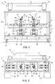
- Fig. 3 is a side view of the apparatus of Figure 1;
- Fig. 4 is a block diagram showing the control circuit for the apparatus of Figure 1;
- Figs. 5 to 10 show schematically the working steps of a bending cycle which can be performed by the method and by the apparatus for automatic bending according to the invention.
-
- As shown in Figures 1 to 3, the apparatus substantially comprises a
bending press 10 as well as arobotised device 11 for picking up and manipulating the metal sheets which are to be bent according to a programmed bending scheme. - The
bending press 10 can be of any conventional type, for example it can consist of a hydraulic press having aframe structure 12 for supporting alower mould member 13 and respectively anupper mould member 14 vertically reciprocable in respect to thefixed mould member 13, for example by means of a pair ofhydraulic cylinders 15. - In the case shown, the
press 10 is of the type comprising an upper movable mould member; however it may also be of the type having a lower movable mould member, or with both mould members which are moving relatively one in relation to the other. -
Reference 16 in Figure 3 denotes a front sensor for the positioning of a metal sheet between the mould members of the press, which together with side sensors supply control signals indicative of the presence and correct positioning of the metal sheet between themould members -
Reference 17 in Figure 3 finally denotes a signal generator, of the linear and absolute type, directly or indirectly interlocked to themovable mould member 14 to supply reference signals indicative of the positions reached by the samemovable mould member 14 during its forward movement towards thelower mould member 13, to allow a correct performance of each bending operation of a sheet. - According to the invention the
robotised device 11 for picking up and manipulating metal sheets to be bent in a bending press, substantially comprises abase frame 18 for supporting a first manipulator or robotisedarm 19, as well as asecond manipulator 20, the twin or wholly identical to the previous one. - The
manipulators bending press 10, on a pair of tracks orguides 21 which parallely extend above the longitudinal sides of thesupport base 18. Thesupport base 18 is also provided with pivotable orcastor wheels 22 which allow its movement and correct positioning in relation to thepress 10. - A
bridge frame 23 extends upwards from thebase 18 to support an electronic equipment for controlling the twomanipulators press 10 in the manner described hereinunder. - Each manipulator, for example the
manipulator 19, comprises in turn abase body 24 provided with wheels orrunners 25 moving along theguides 21. The lateral movement of eachmanipulator electric motor 26 is provided for a pair ofcogged wheels 27, each of which engages with acogged belt 28 stretched between twocross members 29 at the ends of thesupport base 18. - Each
manipulator arm 30 provided with agripping member 31 which can be moved on four polar rotational axes. More particularly the articulatedarm 30 comprises afirst arm portion 30A capable of rotating around ahorizontal axis 32 parallel to theguides 21, under the control of afirst drive motor 33. - The articulated
arm 30 also comprises a second arm portion 30B capable of rotating around a secondhorizontal axis 34, parallel to the previous one, under the control of asecond drive motor 35. - In turn the
gripping member 31 is provided with twodrive motors member 31. The various motors for driving the two manipulators are also fitted with respective encoders or signal generators for providing reference signals which at all times give information on the exact position in space of thegripping member 31. - Finally,
reference 36 in Figure 2 denotes the position for loading or picking up of the metal sheets to be bent, while 37 denotes the unloading or releasing position for the bent pieces. - The working area of the two
manipulators support base 18 in that physically thearticulated arm 30 of each manipulator can pick up and release the metal sheets alongside thepress 10, or it can use a zone to the rear of thebase 18 by simple rotation in a vertical plane of the articulated arm. Themanipulators - Figure 4 of the accompanying drawings shows schematically the electronic device for the control and slaving of the two
manipulators bending press 10. - As indicated schematically in Figure 4, the electronic control device comprises a
microprocessor 40 having a volatile memory, for example a RAM, wherein a program may be stored for controlling and slaving the twomanipulators press 10, by means of the position signals supplied to themicroprocessor 40 by thesensor 17 via a digital-analogic converter 41. - Program and calculation means are also provided comprising an appropriate algorithm or mathematical formula for computing the co-ordinates of the translation and rotational movements of the
gripping member 31 of each manipulator, in accordance with the movement of the metal sheet during bending into the press. The algorithm is stored in apermanent memory 42, for example an EPROM, connected to themicroprocessor 40 via thebus 43. Moreover,reference 44 denotes a further programmable and erasable memory, for example an EEPROM wherein some variable calculation data are programmed and/or stored, such as for example the maximum width of the bending cavity of themould member 13 and the zero point on the Z axis of themovable mould member 14, on the basis of which themicroprocessor 40 will calculate the co-ordinates of movement of the grippingmember 31 for the metal sheets to be bent. All this is known and explained in greater detail in the application EP-A-O 742 054 mentioned previously. - Finally 45 and 46 in Figure 4 denote the internal CPU which selectively controls the movements of each of the two
manipulators - With reference now to Figures 5 to 10, we will describe the working mode of the entire apparatus and the fundamental steps of the process for automatic bending of metal sheets, according to the invention.
- As mentioned previously, the apparatus comprises a bending
press 10 and arobotised device 11 for picking up and manipulating metal sheets to be bent, which is slaved to the press itself. - The robotised device, as referred previously, is formed by two independent manipulators or
robots first manipulator 19 picks up ametal sheet 50 from a stack in theloading position 36 at one end of the support and guidestructure 18, while theother manipulator 20 is at a standstill facing thepress 10 in a waiting or stand-by condition (Figure 5). - The
first manipulator 19, once it has taken asheet 50, rotates its articulatedarm 30 forwards, towards thepress 10, disposing in the working position of Figure 6, in which it performs a first part of the working cycle for bending themetal sheet 50 previously picked up and correctly positioned between the mould members of thepress 10, under the control of themicroprocessor 40, as a function of the control signals supplied by the position sensor orsensors second manipulator 20 remains standstill in the previous waiting condition. - Having completed the first bending steps for the
sheet 50 by means of thefirst manipulator 19, the latter releases the partiallybent sheet 50 which is left clamped between theclosed mould members second manipulator 20 moves towards the bent sheet clamped by the bending mould members and in the brief instant for clamping of the partially bent sheet by saidsecond manipulator 20, thefirst manipulator 19 moves again to the left (Figure 7) into the picking up position to pick up anew metal sheet 51, while thesecond manipulator 20, which was already ready, is slaved to thepress 10 and moves its articulated arm towards themetal sheet 50, already partially bent, taking it with its gripping member in the correct position, after which thesame manipulator 20 returns to the previous working position (Figure 8) where it completes the cycle of bending of thesheet 50 as a function of the programmed work program. - In the meantime the
first manipulator 19 has already taken from the stack thenew metal sheet 51 to be bent, in turn adopting a waiting or stand-by condition. - Having ended the bending cycle of the
first sheet 50, themanipulator 20 moves completely to the right in Figure 9, where it rotates at the rear its articulatedarm 30 to release and deposit the bent metal sheet orpiece 50 in theunloading zone 37. In the meantime thefirst manipulator 19 is slaved again to thepress 10 in order to position thenew metal sheet 51 between themould members unloading zone 37. - The working cycle of the entire apparatus can thus be cyclically repeated and continue in the manner described above. The great advantage of the apparatus and method according to the invention is therefore linked to the alternate use of the two
manipulators - As regards programming, as referred previously, the method is the same as that referred to for the apparatus described in the previous European patent application EP-A-O 742 054, to which reference is made, with the sole difference that now the bending program is divided into two separate parts, each related to one of the two
manipulators - The apparatus, as described hitherto, can be used for bending both asymmetrical and symmetrical pieces.
- In this latter case the apparatus allows the two manipulators to be simultaneously used to conjointly perform the two separated parts of the bending cycle on separate sheets.
- In this respect, at the start of each cycle, the
first manipulator 19 picks up a metal sheet from the stack in thezone 36 and performs the first half of the bends on it. Subsequently, as in the previous bending cycle, themanipulator 19 releases the partially bent sheet clamped in the press in order to pick up a new sheet. In the meantime the second manipulator moves in the position, takes the first partially bent sheet still clamped between the mould members of the press and completes its bending. Given the symmetry of the piece to be made, this latter operation can take place simultaneously with the bending of the new metal sheet taken from the first manipulator. - In practice the two
manipulators - From what has been said and shown by the accompanying drawings it is therefore clear that apparatus has been supplied for automatic bending of metal sheets which allows an entire bending cycle to be performed sequentially on a same sheet, totally eliminating the dead times of the press normally required for the operations of picking up a sheet and releasing or depositing a bent piece, which are now performed while one of the two manipulators operates and performs part of the bending cycle of a sheet.
- It is understood however that what has been said and shown with reference to the accompanying drawings has been given purely by way of a non-limiting example of the general features of the apparatus and method according to the invention; therefore other changes or variants may be made without thereby departing from the present invention.
Claims (12)
- Method for automatic bending operations on a metal sheet to perform a bent piece by means of a press (10) and by a first (19) and by a second (20) manipulator slaved to said press (10), characterised by the steps of:a) picking up a first sheet (50) in a loading zone (36) by the first one (19) of said manipulators (19, 20);b) performing a first set of bends on said first metal sheet (50) during a first working step of the bending cycle with the metal sheet retained and moved under controlled condition by first manipulator (19), maintaining the second manipulator (20) in a stand-by condition;c) clamping the partially bent sheet between mould members (13, 14) of the press (10) at the end of step b), releasing the metal sheet (50) by the first manipulator (19);d) taking the partially bent sheet (50) by the second manipulator (20), while the same sheet (50) is held tightened between the mould members (13, 14) of the bending press (10);e) completing the bending cycle for said first sheet performing a second set of bends by means of the second manipulator (20) to obtain a bent piece; andf) releasing the bent piece (50) by said second manipulator (20) at the end of the step e) and discharging said piece (50) in an unloading zone (37).
- Method according to claim 1, characterized by the additional step of picking up a further metal sheet (51) by means of the first manipulator (19), while the second manipulator (20) is taking said first sheet clamped between the mould members (13, 14) of the press; and performing a set of bends on said further metal sheet according to steps b) to f) of said first metal sheet (50).
- Method according to claim 1 characterized by the additional step of picking up a further metal sheet (51) by means of the first manipulator (19), while the second manipulator (20) is performing said second set of bends step e), and performing a set of bends on said further metal sheet (51) according to step b) to f) of said first metal sheet (50).
- Method for automatic bending operations on a metal sheet, to perform a bent piece on a press (10), moving said sheet by a first (19) and by a second (20) manipulator slaved to said press (10), in particular for bending symmetrical pieces, characterised by the steps of:i) picking up a first metal sheet (50) by the first one (19) of said manipulators (19, 20);ii) performing a first set of bending operations on said first metal sheet (50), with said metal (50) sheet retained and moved between mould members (13, 14) of the press (10) by the first manipulator (19);iii) clamping said partially bent first sheet (50) between the mould members (13, 14) of the press (10) at the end of the step ii), releasing said partially bent first sheet (50) by the first manipulator (19);iv) taking the first partially bent sheet by the second manipulator (20) while the same first sheet is tightly held between the mould members (13, 14);v) picking up a further metal sheet (51) by the first manipulator (19); andvi)conjointly bending said first metal sheet (50) and said further metal sheet (51) held by said first (19) and respectively by said second (20) manipulator, performing said first set of bending operations on said further metal sheet (51), and completing the bending cycle by performing a second set of bending operations on said first metal sheet (50) corresponding to said first bending operations performed on said first metal sheet (50).
- Apparatus for automatic bending of metal sheets (50) to perform a bent piece comprising:a bending press (10) having upper and lower mould members (13, 14) movably supported one in relation to the other to bend a metal sheet (50) positioned therebetween; andactuator means (15) for reciprocating at least one (14) of said mould members (13, 14);a robotised device (11) for picking up and positioning said metal sheet for bending between said mould members (13, 14) of the press (10) characterised in that said robotised device (11) comprises:a support structure having a base portion (18) provided with guides (21) longitudinally extending and parallely arranged to a front side of the bending press (10);first and second manipulators (19, 20) longitudinally movable on the guides (21), each manipulator (19, 20) having an articulated arm (30) provided with a gripping member (31) for retaining said metal sheet (50);programmable control means (40-46), said programmable control means (40-46) for selectively operate the manipulators (19, 20) to pick up a metal sheet (50) by the first one (19) of said manipulators (19, 20), and to sequentially perform first and second sets of bending operations by said first and second manipulators (19, 20) respectively, on said metal sheet (50).
- Apparatus according to claim 5 characterized in that said programmable control means (40-46) comprises a programmable control unit (CPU) for each manipulator (19, 20), said control unit (CPU) being programmed to allow the manipulator (19, 20) to perform a respective set of bending operations by the bending press, on said metal sheet (50).
- Apparatus according to preceding claims 5 and 6 characterized in that the control unit (CPU) of the first manipulator (19) is programmed to perform by said first manipulator (19) a first set of bending operations on a metal sheet (50), and in that the control unit (CPU) of the second manipulator (20) is programmed to perform by said second manipulator (20) a second set of bending operations which differs from the set of bending operations performed by the first manipulator (19) of the robotised device (11).
- Apparatus according to preceding claims 5 and 6 characterized in that the control unit (CPU) of the first manipulator (19) is programmed to perform by said first manipulator (19) a first set of bending operations on a metal sheet (50), and in that the control unit (CPU) of the second manipulator (20) is programmed to perform by said second manipulator (20) a second set of bending operations which corresponds to the set of bending operations performed by the first manipulator (19) of the robotised device (11).
- Apparatus according to claim 8 characterized in that the control units (CPU) of the manipulator (19, 20) are programmed to conjointly perform said first and second sets of bending operations on different metal sheets and in different position of the mould members (13, 14) of the bending press (10).
- Apparatus according to claim 5 characterized in that said control means (40-46) comprises a control unit (CPU) for selectively slaving each of said manipulators (19, 20) to a control unit of the bending press (10).
- Apparatus according to any one of the previous claims, characterised in that each manipulator is of the anthropomorphic type.
- Apparatus according to anyone of the previous claims, characterised in that each manipulator comprises an articulated arm (30) and drive means (40-46) to rotate said arm (30) from a backward position to a forward position of the support structure (23), facing a front side of the press (10).
Applications Claiming Priority (2)
| Application Number | Priority Date | Filing Date | Title |
|---|---|---|---|
| ITMI972453 | 1997-10-31 | ||
| ITMI972453 IT1295906B1 (en) | 1997-10-31 | 1997-10-31 | PROCEDURE AND EQUIPMENT FOR AUTOMATIC FOLDING OF SHEETS IN SHEETS |
Publications (2)
| Publication Number | Publication Date |
|---|---|
| EP0914879A1 true EP0914879A1 (en) | 1999-05-12 |
| EP0914879B1 EP0914879B1 (en) | 2004-05-12 |
Family
ID=11378140
Family Applications (1)
| Application Number | Title | Priority Date | Filing Date |
|---|---|---|---|
| EP19980119190 Expired - Lifetime EP0914879B1 (en) | 1997-10-31 | 1998-10-12 | Method and apparatus for automatic bending of metal sheets |
Country Status (4)
| Country | Link |
|---|---|
| EP (1) | EP0914879B1 (en) |
| DE (1) | DE69823773T2 (en) |
| ES (1) | ES2218742T3 (en) |
| IT (1) | IT1295906B1 (en) |
Cited By (6)
| Publication number | Priority date | Publication date | Assignee | Title |
|---|---|---|---|---|
| WO2003095125A3 (en) * | 2002-05-13 | 2003-12-18 | Trumpf Maschinen Austria Gmbh | Production device, especially a bending press, and method for operating said production device |
| US6938454B2 (en) | 2002-05-13 | 2005-09-06 | Trumpf Maschinen Austria Gmbh & Co. Kg. | Production device, especially a bending press, and method for operating said production device |
| NL1028129C2 (en) * | 2005-01-26 | 2006-07-27 | Safan Bv | Press for bending sheet material comprises manipulators that can be operated independently to insert the sheet material in a desired position |
| WO2018121838A1 (en) * | 2016-12-27 | 2018-07-05 | Abb Schweiz Ag | A pendular handling system for a press line |
| WO2021016646A1 (en) * | 2019-08-01 | 2021-02-04 | Trumpf Maschinen Austria Gmbh & Co. Kg. | Transfer method, manipulation system designed therefor, and bending unit |
| CN114502295A (en) * | 2019-10-10 | 2022-05-13 | 特鲁普机械奥地利有限公司及两合公司 | Method for transporting and/or handling components |
Families Citing this family (3)
| Publication number | Priority date | Publication date | Assignee | Title |
|---|---|---|---|---|
| DE102005060763A1 (en) * | 2005-12-16 | 2007-06-21 | Klingel, Hans, Dr. Ing. e.h. | Binding machine for forming sheet metal workpiece between complementary cross-section designs, has tool changing device for filling of tool carriers, and positioning unit by which the workpieces are bringable in position for machining |
| WO2012019220A1 (en) * | 2010-08-13 | 2012-02-16 | Paul Robert Mccleary | A sheet support assembly |
| CN110586729B (en) * | 2019-09-18 | 2021-06-29 | 上海电机学院 | An automatic stamping device for long-axis complex stamping parts |
Citations (3)
| Publication number | Priority date | Publication date | Assignee | Title |
|---|---|---|---|---|
| US4594870A (en) * | 1982-11-25 | 1986-06-17 | Shin-Meiwa Industry Co., Ltd. | Automatic bending apparatus |
| EP0555908A1 (en) * | 1992-02-14 | 1993-08-18 | L.V.D. Company N.V. | Folding robot |
| US5345806A (en) * | 1989-12-29 | 1994-09-13 | Amada Company, Limited | Device for manipulating sheet metal pieces |
-
1997
- 1997-10-31 IT ITMI972453 patent/IT1295906B1/en active IP Right Grant
-
1998
- 1998-10-12 ES ES98119190T patent/ES2218742T3/en not_active Expired - Lifetime
- 1998-10-12 EP EP19980119190 patent/EP0914879B1/en not_active Expired - Lifetime
- 1998-10-12 DE DE69823773T patent/DE69823773T2/en not_active Expired - Lifetime
Patent Citations (3)
| Publication number | Priority date | Publication date | Assignee | Title |
|---|---|---|---|---|
| US4594870A (en) * | 1982-11-25 | 1986-06-17 | Shin-Meiwa Industry Co., Ltd. | Automatic bending apparatus |
| US5345806A (en) * | 1989-12-29 | 1994-09-13 | Amada Company, Limited | Device for manipulating sheet metal pieces |
| EP0555908A1 (en) * | 1992-02-14 | 1993-08-18 | L.V.D. Company N.V. | Folding robot |
Cited By (15)
| Publication number | Priority date | Publication date | Assignee | Title |
|---|---|---|---|---|
| US6938454B2 (en) | 2002-05-13 | 2005-09-06 | Trumpf Maschinen Austria Gmbh & Co. Kg. | Production device, especially a bending press, and method for operating said production device |
| EP1681111A1 (en) * | 2002-05-13 | 2006-07-19 | Trumpf Maschinen Austria GmbH & CO. KG. | Manufacturing device, in particular bending press, and method for operating said manufacturing device |
| WO2003095125A3 (en) * | 2002-05-13 | 2003-12-18 | Trumpf Maschinen Austria Gmbh | Production device, especially a bending press, and method for operating said production device |
| NL1028129C2 (en) * | 2005-01-26 | 2006-07-27 | Safan Bv | Press for bending sheet material comprises manipulators that can be operated independently to insert the sheet material in a desired position |
| US11278951B2 (en) | 2016-12-27 | 2022-03-22 | Abb Schweiz Ag | Pendular handling system for a press line |
| WO2018121838A1 (en) * | 2016-12-27 | 2018-07-05 | Abb Schweiz Ag | A pendular handling system for a press line |
| CN110167718A (en) * | 2016-12-27 | 2019-08-23 | Abb瑞士股份公司 | Pendulum processing system for press line |
| WO2021016646A1 (en) * | 2019-08-01 | 2021-02-04 | Trumpf Maschinen Austria Gmbh & Co. Kg. | Transfer method, manipulation system designed therefor, and bending unit |
| CN114206522A (en) * | 2019-08-01 | 2022-03-18 | 特鲁普机械奥地利有限公司及两合公司 | Transfer method, handling system and bending equipment designed for this purpose |
| US20220314298A1 (en) * | 2019-08-01 | 2022-10-06 | Trumpf Maschinen Austria Gmbh & Co. Kg. | Transfer method, manipulation system designed therefor, and bending installation |
| JP2022543096A (en) * | 2019-08-01 | 2022-10-07 | トルンプ マシーネン オーストリア ゲゼルシャフト ミット ベシュレンクテル ハフツング ウント コンパニー コマンディトゲゼルシャフト | Transfer method, operating system and bending device configured therefor |
| CN114502295A (en) * | 2019-10-10 | 2022-05-13 | 特鲁普机械奥地利有限公司及两合公司 | Method for transporting and/or handling components |
| JP2023502316A (en) * | 2019-10-10 | 2023-01-24 | トルンプ マシーネン オーストリア ゲゼルシャフト ミット ベシュレンクテル ハフツング ウント コンパニー コマンディトゲゼルシャフト | Method of transporting and/or manipulating components |
| CN114502295B (en) * | 2019-10-10 | 2025-03-18 | 特鲁普机械奥地利有限公司及两合公司 | Method for transporting and/or manipulating components |
| US12434291B2 (en) | 2019-10-10 | 2025-10-07 | Trumpf Maschinen Austria Gmbh & Co. Kg | Method for the transport and/or handling of components |
Also Published As
| Publication number | Publication date |
|---|---|
| EP0914879B1 (en) | 2004-05-12 |
| IT1295906B1 (en) | 1999-05-28 |
| ES2218742T3 (en) | 2004-11-16 |
| ITMI972453A1 (en) | 1999-05-01 |
| DE69823773D1 (en) | 2004-06-17 |
| DE69823773T2 (en) | 2005-05-12 |
Similar Documents
| Publication | Publication Date | Title |
|---|---|---|
| JP5243087B2 (en) | Handling manipulator device | |
| EP0554533B1 (en) | Wire bending apparatus | |
| US7721582B2 (en) | Bending machine for rod-shaped workpieces made from wire, tubular material or the like | |
| CN1733579A (en) | Transfer robot system comprising a manipulator and a temporary container depository moving synchronously with the manipulator | |
| US4594870A (en) | Automatic bending apparatus | |
| EP0914879B1 (en) | Method and apparatus for automatic bending of metal sheets | |
| KR920009855B1 (en) | Automated processing device and metal sheet bending system | |
| CN102348518B (en) | The sheet metal comprising tool holder for sheet-metal working machine loads and unloading unit | |
| GB2215247A (en) | Plate bending machine with manipulator and position control | |
| TWI665150B (en) | Robots and robot systems | |
| JPH06143084A (en) | How to operate a dual-arm robot | |
| JPH0666982U (en) | Plate material gripping device | |
| EP0648577B1 (en) | Apparatus for shaping bars, particularly bars of reinforced concrete | |
| US20060123871A1 (en) | Method and device for reshaping a work piece with automatic handling | |
| JPH06320364A (en) | Part automatic assembling device | |
| JPH08216073A (en) | Robot for loading and unloading work | |
| JPH03128126A (en) | press brake robot | |
| JP2022543096A (en) | Transfer method, operating system and bending device configured therefor | |
| JP2862872B2 (en) | Control method of industrial robot to supply and position plate material to bending machine | |
| JPH0133252B2 (en) | ||
| JP3519092B2 (en) | Work handling method and apparatus by robot | |
| CN107030160B (en) | Flanging device and method for making component flange | |
| CN221186571U (en) | Manipulator for grabbing castings | |
| USRE34569E (en) | Robotized handling device and sheet metal bending system featuring the same | |
| JP2663849B2 (en) | Processing equipment |
Legal Events
| Date | Code | Title | Description |
|---|---|---|---|
| PUAI | Public reference made under article 153(3) epc to a published international application that has entered the european phase |
Free format text: ORIGINAL CODE: 0009012 |
|
| AK | Designated contracting states |
Kind code of ref document: A1 Designated state(s): DE ES FR GB IT |
|
| AX | Request for extension of the european patent |
Free format text: AL;LT;LV;MK;RO;SI |
|
| 17P | Request for examination filed |
Effective date: 19991029 |
|
| AKX | Designation fees paid |
Free format text: DE ES FR GB IT |
|
| 17Q | First examination report despatched |
Effective date: 20030212 |
|
| GRAP | Despatch of communication of intention to grant a patent |
Free format text: ORIGINAL CODE: EPIDOSNIGR1 |
|
| GRAS | Grant fee paid |
Free format text: ORIGINAL CODE: EPIDOSNIGR3 |
|
| GRAA | (expected) grant |
Free format text: ORIGINAL CODE: 0009210 |
|
| RAP1 | Party data changed (applicant data changed or rights of an application transferred) |
Owner name: ANTIL S.P.A. |
|
| RAP1 | Party data changed (applicant data changed or rights of an application transferred) |
Owner name: ANTIL S.P.A. |
|
| AK | Designated contracting states |
Kind code of ref document: B1 Designated state(s): DE ES FR GB IT |
|
| REG | Reference to a national code |
Ref country code: GB Ref legal event code: FG4D |
|
| REF | Corresponds to: |
Ref document number: 69823773 Country of ref document: DE Date of ref document: 20040617 Kind code of ref document: P |
|
| REG | Reference to a national code |
Ref country code: ES Ref legal event code: FG2A Ref document number: 2218742 Country of ref document: ES Kind code of ref document: T3 |
|
| ET | Fr: translation filed | ||
| PLBE | No opposition filed within time limit |
Free format text: ORIGINAL CODE: 0009261 |
|
| STAA | Information on the status of an ep patent application or granted ep patent |
Free format text: STATUS: NO OPPOSITION FILED WITHIN TIME LIMIT |
|
| 26N | No opposition filed |
Effective date: 20050215 |
|
| PGFP | Annual fee paid to national office [announced via postgrant information from national office to epo] |
Ref country code: DE Payment date: 20101013 Year of fee payment: 13 |
|
| PGFP | Annual fee paid to national office [announced via postgrant information from national office to epo] |
Ref country code: GB Payment date: 20101014 Year of fee payment: 13 Ref country code: IT Payment date: 20101021 Year of fee payment: 13 |
|
| PGFP | Annual fee paid to national office [announced via postgrant information from national office to epo] |
Ref country code: ES Payment date: 20111025 Year of fee payment: 14 Ref country code: FR Payment date: 20111104 Year of fee payment: 14 |
|
| GBPC | Gb: european patent ceased through non-payment of renewal fee |
Effective date: 20121012 |
|
| REG | Reference to a national code |
Ref country code: FR Ref legal event code: ST Effective date: 20130628 |
|
| PG25 | Lapsed in a contracting state [announced via postgrant information from national office to epo] |
Ref country code: DE Free format text: LAPSE BECAUSE OF NON-PAYMENT OF DUE FEES Effective date: 20130501 Ref country code: GB Free format text: LAPSE BECAUSE OF NON-PAYMENT OF DUE FEES Effective date: 20121012 |
|
| REG | Reference to a national code |
Ref country code: DE Ref legal event code: R119 Ref document number: 69823773 Country of ref document: DE Effective date: 20130501 |
|
| PG25 | Lapsed in a contracting state [announced via postgrant information from national office to epo] |
Ref country code: FR Free format text: LAPSE BECAUSE OF NON-PAYMENT OF DUE FEES Effective date: 20121031 Ref country code: IT Free format text: LAPSE BECAUSE OF NON-PAYMENT OF DUE FEES Effective date: 20121012 |
|
| REG | Reference to a national code |
Ref country code: ES Ref legal event code: FD2A Effective date: 20140116 |
|
| PG25 | Lapsed in a contracting state [announced via postgrant information from national office to epo] |
Ref country code: ES Free format text: LAPSE BECAUSE OF NON-PAYMENT OF DUE FEES Effective date: 20121013 |