EP0914267B1 - Poutre de pare-chocs et son procede de realisation - Google Patents
Poutre de pare-chocs et son procede de realisation Download PDFInfo
- Publication number
- EP0914267B1 EP0914267B1 EP98925770A EP98925770A EP0914267B1 EP 0914267 B1 EP0914267 B1 EP 0914267B1 EP 98925770 A EP98925770 A EP 98925770A EP 98925770 A EP98925770 A EP 98925770A EP 0914267 B1 EP0914267 B1 EP 0914267B1
- Authority
- EP
- European Patent Office
- Prior art keywords
- mould
- thermoplastic
- mouldable thermoplastic
- drape
- cavity
- Prior art date
- Legal status (The legal status is an assumption and is not a legal conclusion. Google has not performed a legal analysis and makes no representation as to the accuracy of the status listed.)
- Expired - Lifetime
Links
Images

Classifications
-
- B—PERFORMING OPERATIONS; TRANSPORTING
- B60—VEHICLES IN GENERAL
- B60R—VEHICLES, VEHICLE FITTINGS, OR VEHICLE PARTS, NOT OTHERWISE PROVIDED FOR
- B60R19/00—Wheel guards; Radiator guards, e.g. grilles; Obstruction removers; Fittings damping bouncing force in collisions
- B60R19/02—Bumpers, i.e. impact receiving or absorbing members for protecting vehicles or fending off blows from other vehicles or objects
- B60R19/24—Arrangements for mounting bumpers on vehicles
- B60R19/26—Arrangements for mounting bumpers on vehicles comprising yieldable mounting means
- B60R19/36—Combinations of yieldable mounting means of different types
-
- B—PERFORMING OPERATIONS; TRANSPORTING
- B29—WORKING OF PLASTICS; WORKING OF SUBSTANCES IN A PLASTIC STATE IN GENERAL
- B29C—SHAPING OR JOINING OF PLASTICS; SHAPING OF MATERIAL IN A PLASTIC STATE, NOT OTHERWISE PROVIDED FOR; AFTER-TREATMENT OF THE SHAPED PRODUCTS, e.g. REPAIRING
- B29C43/00—Compression moulding, i.e. applying external pressure to flow the moulding material; Apparatus therefor
- B29C43/02—Compression moulding, i.e. applying external pressure to flow the moulding material; Apparatus therefor of articles of definite length, i.e. discrete articles
-
- B—PERFORMING OPERATIONS; TRANSPORTING
- B29—WORKING OF PLASTICS; WORKING OF SUBSTANCES IN A PLASTIC STATE IN GENERAL
- B29C—SHAPING OR JOINING OF PLASTICS; SHAPING OF MATERIAL IN A PLASTIC STATE, NOT OTHERWISE PROVIDED FOR; AFTER-TREATMENT OF THE SHAPED PRODUCTS, e.g. REPAIRING
- B29C43/00—Compression moulding, i.e. applying external pressure to flow the moulding material; Apparatus therefor
- B29C43/02—Compression moulding, i.e. applying external pressure to flow the moulding material; Apparatus therefor of articles of definite length, i.e. discrete articles
- B29C43/18—Compression moulding, i.e. applying external pressure to flow the moulding material; Apparatus therefor of articles of definite length, i.e. discrete articles incorporating preformed parts or layers, e.g. compression moulding around inserts or for coating articles
-
- B—PERFORMING OPERATIONS; TRANSPORTING
- B29—WORKING OF PLASTICS; WORKING OF SUBSTANCES IN A PLASTIC STATE IN GENERAL
- B29C—SHAPING OR JOINING OF PLASTICS; SHAPING OF MATERIAL IN A PLASTIC STATE, NOT OTHERWISE PROVIDED FOR; AFTER-TREATMENT OF THE SHAPED PRODUCTS, e.g. REPAIRING
- B29C43/00—Compression moulding, i.e. applying external pressure to flow the moulding material; Apparatus therefor
- B29C43/02—Compression moulding, i.e. applying external pressure to flow the moulding material; Apparatus therefor of articles of definite length, i.e. discrete articles
- B29C43/20—Making multilayered or multicoloured articles
- B29C43/203—Making multilayered articles
-
- B—PERFORMING OPERATIONS; TRANSPORTING
- B29—WORKING OF PLASTICS; WORKING OF SUBSTANCES IN A PLASTIC STATE IN GENERAL
- B29C—SHAPING OR JOINING OF PLASTICS; SHAPING OF MATERIAL IN A PLASTIC STATE, NOT OTHERWISE PROVIDED FOR; AFTER-TREATMENT OF THE SHAPED PRODUCTS, e.g. REPAIRING
- B29C70/00—Shaping composites, i.e. plastics material comprising reinforcements, fillers or preformed parts, e.g. inserts
- B29C70/04—Shaping composites, i.e. plastics material comprising reinforcements, fillers or preformed parts, e.g. inserts comprising reinforcements only, e.g. self-reinforcing plastics
- B29C70/28—Shaping operations therefor
- B29C70/40—Shaping or impregnating by compression not applied
- B29C70/42—Shaping or impregnating by compression not applied for producing articles of definite length, i.e. discrete articles
- B29C70/46—Shaping or impregnating by compression not applied for producing articles of definite length, i.e. discrete articles using matched moulds, e.g. for deforming sheet moulding compounds [SMC] or prepregs
-
- B—PERFORMING OPERATIONS; TRANSPORTING
- B29—WORKING OF PLASTICS; WORKING OF SUBSTANCES IN A PLASTIC STATE IN GENERAL
- B29K—INDEXING SCHEME ASSOCIATED WITH SUBCLASSES B29B, B29C OR B29D, RELATING TO MOULDING MATERIALS OR TO MATERIALS FOR MOULDS, REINFORCEMENTS, FILLERS OR PREFORMED PARTS, e.g. INSERTS
- B29K2105/00—Condition, form or state of moulded material or of the material to be shaped
- B29K2105/06—Condition, form or state of moulded material or of the material to be shaped containing reinforcements, fillers or inserts
-
- B—PERFORMING OPERATIONS; TRANSPORTING
- B29—WORKING OF PLASTICS; WORKING OF SUBSTANCES IN A PLASTIC STATE IN GENERAL
- B29K—INDEXING SCHEME ASSOCIATED WITH SUBCLASSES B29B, B29C OR B29D, RELATING TO MOULDING MATERIALS OR TO MATERIALS FOR MOULDS, REINFORCEMENTS, FILLERS OR PREFORMED PARTS, e.g. INSERTS
- B29K2105/00—Condition, form or state of moulded material or of the material to be shaped
- B29K2105/06—Condition, form or state of moulded material or of the material to be shaped containing reinforcements, fillers or inserts
- B29K2105/08—Condition, form or state of moulded material or of the material to be shaped containing reinforcements, fillers or inserts of continuous length, e.g. cords, rovings, mats, fabrics, strands or yarns
- B29K2105/0854—Condition, form or state of moulded material or of the material to be shaped containing reinforcements, fillers or inserts of continuous length, e.g. cords, rovings, mats, fabrics, strands or yarns in the form of a non-woven mat
-
- B—PERFORMING OPERATIONS; TRANSPORTING
- B29—WORKING OF PLASTICS; WORKING OF SUBSTANCES IN A PLASTIC STATE IN GENERAL
- B29K—INDEXING SCHEME ASSOCIATED WITH SUBCLASSES B29B, B29C OR B29D, RELATING TO MOULDING MATERIALS OR TO MATERIALS FOR MOULDS, REINFORCEMENTS, FILLERS OR PREFORMED PARTS, e.g. INSERTS
- B29K2105/00—Condition, form or state of moulded material or of the material to be shaped
- B29K2105/25—Solid
- B29K2105/253—Preform
- B29K2105/256—Sheets, plates, blanks or films
-
- B—PERFORMING OPERATIONS; TRANSPORTING
- B29—WORKING OF PLASTICS; WORKING OF SUBSTANCES IN A PLASTIC STATE IN GENERAL
- B29L—INDEXING SCHEME ASSOCIATED WITH SUBCLASS B29C, RELATING TO PARTICULAR ARTICLES
- B29L2031/00—Other particular articles
- B29L2031/30—Vehicles, e.g. ships or aircraft, or body parts thereof
- B29L2031/3005—Body finishings
- B29L2031/3041—Trim panels
-
- B—PERFORMING OPERATIONS; TRANSPORTING
- B29—WORKING OF PLASTICS; WORKING OF SUBSTANCES IN A PLASTIC STATE IN GENERAL
- B29L—INDEXING SCHEME ASSOCIATED WITH SUBCLASS B29C, RELATING TO PARTICULAR ARTICLES
- B29L2031/00—Other particular articles
- B29L2031/30—Vehicles, e.g. ships or aircraft, or body parts thereof
- B29L2031/3044—Bumpers
-
- B—PERFORMING OPERATIONS; TRANSPORTING
- B60—VEHICLES IN GENERAL
- B60R—VEHICLES, VEHICLE FITTINGS, OR VEHICLE PARTS, NOT OTHERWISE PROVIDED FOR
- B60R19/00—Wheel guards; Radiator guards, e.g. grilles; Obstruction removers; Fittings damping bouncing force in collisions
- B60R19/02—Bumpers, i.e. impact receiving or absorbing members for protecting vehicles or fending off blows from other vehicles or objects
- B60R19/24—Arrangements for mounting bumpers on vehicles
- B60R19/26—Arrangements for mounting bumpers on vehicles comprising yieldable mounting means
- B60R19/28—Metallic springs
- B60R19/285—Metallic springs comprising only leaf springs, e.g. the mounting means forming part of the guard itself
-
- B—PERFORMING OPERATIONS; TRANSPORTING
- B60—VEHICLES IN GENERAL
- B60R—VEHICLES, VEHICLE FITTINGS, OR VEHICLE PARTS, NOT OTHERWISE PROVIDED FOR
- B60R19/00—Wheel guards; Radiator guards, e.g. grilles; Obstruction removers; Fittings damping bouncing force in collisions
- B60R19/02—Bumpers, i.e. impact receiving or absorbing members for protecting vehicles or fending off blows from other vehicles or objects
- B60R19/24—Arrangements for mounting bumpers on vehicles
- B60R19/26—Arrangements for mounting bumpers on vehicles comprising yieldable mounting means
- B60R19/34—Arrangements for mounting bumpers on vehicles comprising yieldable mounting means destroyed upon impact, e.g. one-shot type
Definitions
- the present invention relates to a bumper beam, and its production process.
- a beam according to the preamble of claim 1 and a method according to the preamble of claim 3 are known from document JP-A-4201753.
- Both the beam and the local absorbers are known for be relatively expensive to make, which poses a problem in case repair of an accident vehicle.
- the present invention aims to resolve these drawbacks by proposing a new type of bumper beam.
- the present invention relates to a bumper beam obtained by molding a moldable thermoplastic and a drapable thermoplastic material with continuous fibers.
- This beam is characterized by the fact that it presents, in cross section, a constant developed length.
- This feature allows the use of a plate rectangular of continuous fiber thermoplastic material for mold the beam, the width of the plate corresponding to the developed length of the cross section of the beam.
- mouldable is meant the ability of the thermoplastic to creep in a mold filling all its cavities, whatever their depth
- drapable thermoplastic material is meant a material thermoplastic in the form of a textile sheet pre-consolidated or not which, during molding, can only be deform but substantially retains its initial thickness
- thermoplastic material with continuous fibers can use "Twintex” type thermoplastic prepregs from Vetrotex or "Tepex” from Du Pont de Nemours.
- the beam comprises thickeners of thermoplastic material with continuous fibers.
- the present invention also relates to a method for make a beam as described above.
- This process is characterized by the fact that it consists of set a mold so that the cross section of its footprint has a substantially constant developed length, at place a rectangular plate of thermoplastic material drapable with continuous fibers in the open mold and provide thermoplastic material moldable in the mold for molding the beam.
- the plastic can be supplied by injection, by injection-compression, or by extrusion-compression.
- a mold with a positive joint plane is used and the moldable thermoplastic material is brought into the mold open, for example by injection or extrusion, then we close the mold for compressing the two thermoplastics and causing filling the mold imprint.
- traps of fiber thermoplastic material are trapped continuous between two rectangular plates of material drapable thermoplastic, at the places of the corresponding imprint to extra thicknesses of the beam, and the material is deposited thermoplastic with a high creep coefficient on one side of one of the rectangular plates opposite the plates, before closing the mold.
- the bumper 1 includes a shield 2, a beam 3 and two local absorbers 4 only one of which is visible in the figures.
- Each absorber 4 is mounted at the end of a beam 5 of the vehicle and includes an absorbent element 6 with high efficiency, made for example by extruded honeycomb polycarbonate in the form of a sectional pyramid trunk rectangular.
- the shock absorber also has an elastic member consisting of two U-shaped pieces 7 whose ends are distant of a length substantially equal to that of the absorbent element.
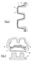
- the developed length L of this section is constant, whatever the cutting plane considered.
- the beam has local excess thicknesses 10 which are obtained by stacking plates 11 of thermoplastic material drape with continuous fibers, judiciously positioned in the mold 12, 13.
- the plates 11 are trapped between two plates rectangular 14 of drapable thermoplastic material, which preferably include continuous fibers, so that when of the closing of the mold, the creep of the thermoplastic material 15 does not cause the displacement of the plates 11 in places mold.
Landscapes
- Engineering & Computer Science (AREA)
- Mechanical Engineering (AREA)
- Casting Or Compression Moulding Of Plastics Or The Like (AREA)
- Vibration Dampers (AREA)
Abstract
Description
- la figure 1 est une vue en perspective d'une extrémité de pare-chocs en vue partiellement éclatée,
- la figure 2 est une vue en section transversale de la poutre du pare-chocs,
- la figure 3 représente le positionnement des plaques et plaquettes de matériau en fibres continues dans le moule lors de la réalisation de la poutre.
Claims (5)
- Poutre de pare-chocs obtenue par moulage d'une matière thermoplastique moulable (15) et d'une matière thermoplastique drapable (14) à fibres continues se présentant sous forme de plaques, caractérisée par le fait qu'elle présente, en section transversale, une longueur développée constante, sur toute la longueur de la poutre.
- Poutre selon la revendication 1, caractérisée par le fait qu'elle comporte des surépaisseurs (10) de matière thermoplastique à fibres continues.
- Procédé pour réaliser une poutre selon l'une quelconque des revendications 1 et 2, caractérisé par le fait qu'il consiste à définir un moule (12,13) de telle sorte que la section transversale de son empreinte présente une longueur développée (L) sensiblement constante sur toute la longueur de l'empreinte, à placer une plaque rectangulaire (14) d'une matière thermoplastique drapable à fibres continues dans le moule ouvert et à apporter de la matière thermoplastique moulable (15) dans le moule pour mouler la poutre.
- Procédé selon la revendication 3, caractérisé par le fait que l'on utilise un moule (12,13) à plan de joint positif et que l'on apporte la matière thermoplastique moulable (15) dans le moule ouvert, puis on ferme le moule pour comprimer les deux matières thermoplastiques (14,15) et provoquer le remplissage de l'empreinte du moule.
- Procédé selon la revendication 4, caractérisé par le fait que l'on emprisonne des plaquettes (11) de matière thermoplastique drapable à fibres continues entre deux plaques rectangulaires (14) de matière thermoplastique drapable, aux endroits de l'empreinte correspondant à des surépaisseurs (10) de la poutre (3), et que l'on dépose la matière thermoplastique moulable (15) d'un côté de l'une des plaques rectangulaires (14) opposé aux plaquettes (11), avant de refermer le moule.
Applications Claiming Priority (3)
| Application Number | Priority Date | Filing Date | Title |
|---|---|---|---|
| FR9706335A FR2763547A1 (fr) | 1997-05-23 | 1997-05-23 | Pare-chocs a absorbeur local |
| FR9706335 | 1997-05-23 | ||
| PCT/FR1998/001031 WO1998052793A1 (fr) | 1997-05-23 | 1998-05-22 | Poutre de pare-chocs et son procede de realisation |
Publications (2)
| Publication Number | Publication Date |
|---|---|
| EP0914267A1 EP0914267A1 (fr) | 1999-05-12 |
| EP0914267B1 true EP0914267B1 (fr) | 2001-11-07 |
Family
ID=9507182
Family Applications (1)
| Application Number | Title | Priority Date | Filing Date |
|---|---|---|---|
| EP98925770A Expired - Lifetime EP0914267B1 (fr) | 1997-05-23 | 1998-05-22 | Poutre de pare-chocs et son procede de realisation |
Country Status (6)
| Country | Link |
|---|---|
| US (1) | US6231094B1 (fr) |
| EP (1) | EP0914267B1 (fr) |
| JP (1) | JP2000515828A (fr) |
| DE (1) | DE69802366T2 (fr) |
| FR (1) | FR2763547A1 (fr) |
| WO (1) | WO1998052793A1 (fr) |
Families Citing this family (23)
| Publication number | Priority date | Publication date | Assignee | Title |
|---|---|---|---|---|
| US7258913B2 (en) * | 2002-10-28 | 2007-08-21 | Certainteed Corp. | Plastic fencing system reinforced with fiberglass reinforced thermoplastic composites |
| EP1060869B1 (fr) * | 1999-06-18 | 2003-11-05 | Blechformwerke Bernsbach AG | Procédé pour la fabrication d'une coque haute performance, platine pour la mise en oeuvre du procédé et coque haute performance obtenue par ce procédé |
| DE19952570A1 (de) * | 1999-11-02 | 2001-05-03 | Bayer Ag | Energieabsorber für ein Absorbieren von Stoßenergie |
| FR2806350B1 (fr) | 2000-03-20 | 2002-12-06 | Plastic Omnium Cie | Piece en matiere plastique renforcee et procede de fabrication |
| ITMI20011170A1 (it) * | 2001-06-01 | 2002-12-01 | Adlev Srl | Struttura di protezione per veicoli, atta ad essere utilizzata, in particolare, nel caso di urti con pedoni |
| US6663150B1 (en) * | 2002-06-06 | 2003-12-16 | Netshape Corporation | Bumper with integrated energy absorber and beam |
| NO20024789D0 (no) * | 2002-10-03 | 2002-10-03 | Norsk Hydro As | Stötfanger |
| EP1443344A1 (fr) * | 2003-01-29 | 2004-08-04 | Heptagon Oy | Production d'éléments à microstructure |
| ITMI20031616A1 (it) * | 2003-08-06 | 2005-02-07 | Adlev Srl | Complesso di paraurti per veicolo e relativo veicolo |
| KR101256688B1 (ko) | 2004-12-06 | 2013-04-19 | 도레이 카부시키가이샤 | 성형 전구체, 섬유 강화 수지 성형체의 제조 방법 및 섬유강화 수지 성형체 |
| ITTV20050101A1 (it) * | 2005-07-12 | 2007-01-13 | Plastal Spa | Paraurti e calandra per veicoli medio-pesanti. |
| KR20080010639A (ko) * | 2006-07-27 | 2008-01-31 | 주식회사 아펙스 | 자동차용 범퍼 보강부재 |
| KR101013901B1 (ko) * | 2007-12-18 | 2011-02-14 | 현대자동차주식회사 | 다단 에너지 완충구조를 갖는 범퍼장치 |
| DE102010013131A1 (de) * | 2009-12-21 | 2011-06-22 | REHAU AG + Co., 95111 | Verfahren zur Herstellung von endlosfaserverstärkten Formteilen aus thermoplastischem Kunststoff sowie Kraftfahrzeugformteil |
| KR101189470B1 (ko) * | 2010-12-06 | 2012-10-12 | 현대자동차주식회사 | 다중 유리섬유 접합식 고강도 플라스틱 백빔 |
| NL2010212C2 (en) * | 2013-01-31 | 2014-08-04 | Voestalpine Polynorm Plastics B V | Method and resulting product of thermoplastic material and comprising a reinforcement. |
| DE102013222923B4 (de) * | 2013-11-11 | 2021-12-30 | Hyundai Motor Company | Herstellungsverfahren für ein aufprallbeständiges Strukturbauteil für ein Kraftfahrzeug, aufprallbeständiges Strukturbauteil für ein Kraftfahrzeug, das nach diesem Verfahren hergestellt wird und Verwendung derselben |
| KR20150072178A (ko) * | 2013-12-19 | 2015-06-29 | 현대자동차주식회사 | 차량용 백빔 |
| JP6137707B2 (ja) | 2015-08-03 | 2017-05-31 | 本田技研工業株式会社 | 自動車用バンパービームの製造方法 |
| KR102187577B1 (ko) * | 2015-08-05 | 2020-12-08 | 현대자동차주식회사 | 범퍼용 빔 |
| SE1750635A1 (en) * | 2017-05-22 | 2018-11-23 | Gestamp Hardtech Ab | Bumper beam with reinforcement patch |
| JP7459687B2 (ja) * | 2020-07-01 | 2024-04-02 | マツダ株式会社 | 車両の前部車体構造 |
| FR3116247A1 (fr) * | 2020-11-18 | 2022-05-20 | Valeo Systemes Thermiques | Ensemble absorbeur d’énergie de choc |
Family Cites Families (20)
| Publication number | Priority date | Publication date | Assignee | Title |
|---|---|---|---|---|
| DE547783C (de) * | 1932-04-06 | Ernest Deveaux | Federnder Traeger fuer Stossstangen von Kraftfahrzeugen | |
| US3663048A (en) * | 1970-04-03 | 1972-05-16 | Gen Motors Corp | Vehicle bumper installation |
| US3933387A (en) * | 1975-03-10 | 1976-01-20 | General Motors Corporation | Thermoformed plastic energy absorber for vehicles |
| GB1575840A (en) * | 1976-03-29 | 1980-10-01 | Budd Co | Bumper spring |
| FR2447300A1 (fr) * | 1979-01-26 | 1980-08-22 | Renault | Contre-lames elastiques pour fixation de pare-chocs de vehicules automobiles |
| US4413856A (en) * | 1981-08-07 | 1983-11-08 | General Motors Corporation | Hardbar energy absorbing bumper system for vehicles |
| US4671550A (en) * | 1985-07-01 | 1987-06-09 | Arpi Co. | Bumper beam |
| JPH0620743B2 (ja) * | 1985-12-26 | 1994-03-23 | 日本板硝子株式会社 | 複合長繊維強化熱可塑性樹脂スタンパブルシ−ト及びそれを成形してなるバンパ−ビ−ム |
| US4904008A (en) * | 1986-09-02 | 1990-02-27 | Concept Analysis Corporation | Molded one-piece bumper |
| EP0272635B1 (fr) * | 1986-12-19 | 1992-08-05 | Takeda Chemical Industries, Ltd. | Procédé de moulage de plastiques renforcés par des fibres |
| DE3833048C2 (de) * | 1988-09-29 | 1994-03-24 | Bayerische Motoren Werke Ag | Stoßfänger für Kraftfahrzeuge, insbesondere Personenkraftwagen |
| US5037599A (en) * | 1989-06-26 | 1991-08-06 | Basf Aktiengesellschaft | Single diaphragm forming of drapeable thermoplastic impregnated composite materials |
| US5141273A (en) * | 1989-10-11 | 1992-08-25 | The Budd Company | Molded composite bumper |
| JPH04208417A (ja) * | 1990-11-30 | 1992-07-30 | Nippon Steel Corp | 繊維強化熱可塑性樹脂成形品及びその成形方法 |
| JPH04201753A (ja) * | 1990-11-30 | 1992-07-22 | Nippon G Ii Plast Kk | バンパービーム |
| US5290079A (en) * | 1992-12-22 | 1994-03-01 | General Motors Corporation | Reinforced composite impact beam for a bumper assembly and method |
| KR960013914A (ko) * | 1994-10-04 | 1996-05-22 | 고오사이 아끼오 | 충격흡수 구조체 |
| FR2749535B1 (fr) * | 1996-06-07 | 1998-08-28 | Manducher Sa | Piece a base de materiau thermoplastique pour vehicule automobile et procede de fabrication de cette piece |
| FR2749796B1 (fr) * | 1996-06-13 | 1998-07-31 | Plastic Omnium Cie | Procede pour realiser une piece en matiere thermoplastique renforcee, poutre de pare-chocs et pare-chocs comprenant une telle poutre |
| US6004650A (en) * | 1996-12-31 | 1999-12-21 | Owens Corning Fiberglas Technology, Inc. | Fiber reinforced composite part and method of making same |
-
1997
- 1997-05-23 FR FR9706335A patent/FR2763547A1/fr active Pending
-
1998
- 1998-05-22 JP JP10550065A patent/JP2000515828A/ja active Pending
- 1998-05-22 DE DE69802366T patent/DE69802366T2/de not_active Expired - Lifetime
- 1998-05-22 WO PCT/FR1998/001031 patent/WO1998052793A1/fr not_active Ceased
- 1998-05-22 EP EP98925770A patent/EP0914267B1/fr not_active Expired - Lifetime
- 1998-05-22 US US09/230,103 patent/US6231094B1/en not_active Expired - Lifetime
Also Published As
| Publication number | Publication date |
|---|---|
| JP2000515828A (ja) | 2000-11-28 |
| US6231094B1 (en) | 2001-05-15 |
| FR2763547A1 (fr) | 1998-11-27 |
| WO1998052793A1 (fr) | 1998-11-26 |
| DE69802366T2 (de) | 2002-07-11 |
| DE69802366D1 (de) | 2001-12-13 |
| EP0914267A1 (fr) | 1999-05-12 |
Similar Documents
| Publication | Publication Date | Title |
|---|---|---|
| WO1998052793A1 (fr) | Poutre de pare-chocs et son procede de realisation | |
| EP0812674B1 (fr) | Procédé pour réaliser une pièce en matière thermoplastique renforcée, poutre de pare-chocs et pare-chocs comprenant une telle poutre | |
| EP1136239B1 (fr) | Procédé de fabrication d'une pièce en matière plastique renforcée et moule | |
| CA2147727A1 (fr) | Face avant technique de vehicule automobile | |
| FR2620628A2 (fr) | Procede pour realiser un ski et ski fait selon ce procede | |
| EP1315606B1 (fr) | Unite de moulage comportant une chambre de compensation delimitee par une membrane, membrane pour une telle unite et machine munie d'une telle unite | |
| WO2003024748A1 (fr) | Poutre de pare-chocs pour vehicule comprenant une traverse et deux absorbeurs de chocs | |
| EP0428885A1 (fr) | Procédé de réalisation d'un ski par injection, et structure de ski | |
| WO2011117546A1 (fr) | Procede de realisation en continu d'une piece de liaison en materiau composite | |
| CA2692294A1 (fr) | Bielle structurale en materiau composite et procede de realisation d 'une telle bielle | |
| EP0269470A2 (fr) | Procédé de fabrication d' un cadre à structure composite | |
| FR2729329A1 (fr) | Procede et dispositif pour la realisation d'une partie au moins d'un moule de pneumatique comportant au moins un element moulant un motif non demoulable | |
| EP0332495B1 (fr) | Procédé de fabrication de pièces de carrosserie d'automobile, notamment d'aileron ou becquet arrière, et pièces obtenues par mise en oeuvre de ce procédé | |
| EP0589116A1 (fr) | Procédé de fabrication d'un objet multicouche par moulage, objet obtenu et application à la fabrication de tableaux de bord et/ou d'éléments d'habillage d'une carrosserie de véhicule | |
| EP0659111B1 (fr) | Procede de fabrication de pieces en matiere plastique par moulage-thermoformage controle | |
| FR2757124A1 (fr) | Carenage sous moteur absorbeur de chocs | |
| EP0081834B1 (fr) | Ski du type à noyau à structure allégée et son procédé de fabrication | |
| FR2763546A1 (fr) | Poutre de pare-chocs et son procede de realisation | |
| FR2957843A1 (fr) | Procede de realisation d'une piece de liaison en materiau composite et piece obtenue | |
| EP3636410B1 (fr) | Procédé de fabrication d'une pièce surmoulée formant pièce structurelle de véhicule | |
| EP0976519A1 (fr) | Procédé d'ancrage d'une masse thermoplastique et pièce obtenue par mise en oeuvre de ce procédé | |
| FR3072322A1 (fr) | Piece en materiau composite avec insert metallique | |
| FR2876945A1 (fr) | Piece thermoplastique renforcee | |
| FR2752769A1 (fr) | Panneau composite renforce notamment pour l'ancrage d'une piece, vehicule automobile equipe de ce panneau et son procede de fabrication | |
| FR3118753A1 (fr) | Pedale de vehicule automobile munie d'un insert de rigidification en materiau composite |
Legal Events
| Date | Code | Title | Description |
|---|---|---|---|
| PUAI | Public reference made under article 153(3) epc to a published international application that has entered the european phase |
Free format text: ORIGINAL CODE: 0009012 |
|
| AK | Designated contracting states |
Kind code of ref document: A1 Designated state(s): DE FR GB IT |
|
| 17P | Request for examination filed |
Effective date: 19990518 |
|
| GRAG | Despatch of communication of intention to grant |
Free format text: ORIGINAL CODE: EPIDOS AGRA |
|
| 17Q | First examination report despatched |
Effective date: 20010313 |
|
| GRAG | Despatch of communication of intention to grant |
Free format text: ORIGINAL CODE: EPIDOS AGRA |
|
| GRAH | Despatch of communication of intention to grant a patent |
Free format text: ORIGINAL CODE: EPIDOS IGRA |
|
| GRAH | Despatch of communication of intention to grant a patent |
Free format text: ORIGINAL CODE: EPIDOS IGRA |
|
| GRAA | (expected) grant |
Free format text: ORIGINAL CODE: 0009210 |
|
| AK | Designated contracting states |
Kind code of ref document: B1 Designated state(s): DE FR GB IT |
|
| REF | Corresponds to: |
Ref document number: 69802366 Country of ref document: DE Date of ref document: 20011213 |
|
| REG | Reference to a national code |
Ref country code: GB Ref legal event code: IF02 |
|
| GBT | Gb: translation of ep patent filed (gb section 77(6)(a)/1977) |
Effective date: 20020124 |
|
| PLBE | No opposition filed within time limit |
Free format text: ORIGINAL CODE: 0009261 |
|
| STAA | Information on the status of an ep patent application or granted ep patent |
Free format text: STATUS: NO OPPOSITION FILED WITHIN TIME LIMIT |
|
| 26N | No opposition filed | ||
| PGFP | Annual fee paid to national office [announced via postgrant information from national office to epo] |
Ref country code: GB Payment date: 20130530 Year of fee payment: 16 Ref country code: DE Payment date: 20130530 Year of fee payment: 16 |
|
| PGFP | Annual fee paid to national office [announced via postgrant information from national office to epo] |
Ref country code: IT Payment date: 20130531 Year of fee payment: 16 |
|
| REG | Reference to a national code |
Ref country code: DE Ref legal event code: R119 Ref document number: 69802366 Country of ref document: DE |
|
| GBPC | Gb: european patent ceased through non-payment of renewal fee |
Effective date: 20140522 |
|
| REG | Reference to a national code |
Ref country code: DE Ref legal event code: R119 Ref document number: 69802366 Country of ref document: DE Effective date: 20141202 |
|
| PG25 | Lapsed in a contracting state [announced via postgrant information from national office to epo] |
Ref country code: IT Free format text: LAPSE BECAUSE OF NON-PAYMENT OF DUE FEES Effective date: 20140522 Ref country code: DE Free format text: LAPSE BECAUSE OF NON-PAYMENT OF DUE FEES Effective date: 20141202 |
|
| REG | Reference to a national code |
Ref country code: FR Ref legal event code: PLFP Year of fee payment: 18 |
|
| PG25 | Lapsed in a contracting state [announced via postgrant information from national office to epo] |
Ref country code: GB Free format text: LAPSE BECAUSE OF NON-PAYMENT OF DUE FEES Effective date: 20140522 |
|
| PGFP | Annual fee paid to national office [announced via postgrant information from national office to epo] |
Ref country code: FR Payment date: 20150528 Year of fee payment: 18 |
|
| REG | Reference to a national code |
Ref country code: FR Ref legal event code: ST Effective date: 20170131 |
|
| PG25 | Lapsed in a contracting state [announced via postgrant information from national office to epo] |
Ref country code: FR Free format text: LAPSE BECAUSE OF NON-PAYMENT OF DUE FEES Effective date: 20160531 |