EP0914031A2 - Cooling apparatus - Google Patents
Cooling apparatus Download PDFInfo
- Publication number
- EP0914031A2 EP0914031A2 EP98120573A EP98120573A EP0914031A2 EP 0914031 A2 EP0914031 A2 EP 0914031A2 EP 98120573 A EP98120573 A EP 98120573A EP 98120573 A EP98120573 A EP 98120573A EP 0914031 A2 EP0914031 A2 EP 0914031A2
- Authority
- EP
- European Patent Office
- Prior art keywords
- nozzle
- coolant
- plate
- duct
- resonance
- Prior art date
- Legal status (The legal status is an assumption and is not a legal conclusion. Google has not performed a legal analysis and makes no representation as to the accuracy of the status listed.)
- Granted
Links
Images


Classifications
-
- H—ELECTRICITY
- H10—SEMICONDUCTOR DEVICES; ELECTRIC SOLID-STATE DEVICES NOT OTHERWISE PROVIDED FOR
- H10W—GENERIC PACKAGES, INTERCONNECTIONS, CONNECTORS OR OTHER CONSTRUCTIONAL DETAILS OF DEVICES COVERED BY CLASS H10
- H10W40/00—Arrangements for thermal protection or thermal control
- H10W40/40—Arrangements for thermal protection or thermal control involving heat exchange by flowing fluids
- H10W40/43—Arrangements for thermal protection or thermal control involving heat exchange by flowing fluids by flowing gases, e.g. forced air cooling
-
- Y—GENERAL TAGGING OF NEW TECHNOLOGICAL DEVELOPMENTS; GENERAL TAGGING OF CROSS-SECTIONAL TECHNOLOGIES SPANNING OVER SEVERAL SECTIONS OF THE IPC; TECHNICAL SUBJECTS COVERED BY FORMER USPC CROSS-REFERENCE ART COLLECTIONS [XRACs] AND DIGESTS
- Y10—TECHNICAL SUBJECTS COVERED BY FORMER USPC
- Y10S—TECHNICAL SUBJECTS COVERED BY FORMER USPC CROSS-REFERENCE ART COLLECTIONS [XRACs] AND DIGESTS
- Y10S165/00—Heat exchange
- Y10S165/908—Fluid jets
Definitions
- the present invention relates to a cooling apparatus in which streams of a coolant are made to blow against an object to cool as jet streams.
- a cooling apparatus is generally used for cooling various electronic devices with generation of heat.
- a cooling apparatus in which a coolant such as air is jetted through nozzles and made to blow directly against an object to cool so that the object is cooled by compulsory heat exchange.
- Japanese Patent Unexamined Publication No. Hei 1-175298 discloses a cooling structure for an electronic circuit.
- the structure includes an air pipe provided with a plurality of nozzles for spouting air, which flows in the pipe, toward an element with a little generation of heat such as a memory IC.
- the structure disclosed in this publication includes a fixing board which is attached to a frame so as to be opposite to a circuit board, a cooling board which is in contact with an element with a great generation of heat through an elastic sheet with a good heat conductivity attached to the fixing board, and is provided in its inside with a flow passage for allowing a liquid coolant to flow, and the air pipe which is attached to the fixing board and provided with the nozzles for spouting air, which flows in the pipe, toward the element with a little generation of heat.
- the element with a little generation of heat is cooled by a so-called collision cooling method.
- Fig. 5 is a cross-sectional side view of a related art cooling apparatus.
- the heat sink 1a of the power amplifier 1 of the television transmitter is opposite to a plurality of nozzles 5, and the duct 2 has the same horizontal cross section throughout its vertical length.
- the quantities of the cooling air streams 6 jetted through the nozzles 5 are uneven in the manner that the lower the nozzle 5 is, the more the quantity is. This causes an inclination in the temperature distribution of the heat sink 1a, and the lower portion of the heat sink 1a is fully cooled but the upper portion of it is hardly cooled.
- jet noise is generated at the nozzles 5 when the cooling air streams 6 are jetted through the nozzles 5. Because this jet noise is a random noise consisting of frequencies in a broad range, it is a mere noise which is heard as a rumble, and does not give so unpleasant feeling to a human in the neighborhood. But in case that the horizontal distance in the duct 2 along the direction in which the cooling air streams 6 are jetted, that is, the horizontal distance l between the nozzle plate 9 and the opposite plate 3 coincides with a resonance distance l 0 which is equal to the wavelength of a specific peak frequency in the jet noise, a resonance occurs to increase the energy of the noise. A big sound like a whistle is therefore generated and it gives an unpleasant feeling to a human in the neighborhood.
- Fig. 6A is an enlarged partial side view in section for illustrating the principle of occurrence of the resonance in the cooling apparatus of Fig. 5.
- Fig. 6B is an enlarged view of a nozzle 5 of Fig. 6A.
- Fig. 7 is an enlarged partial side view in section for illustrating the principle of occurrence of the resonance in the cooling apparatus of Fig. 5.
- the second feature of the present invention is that the cooling apparatus according to the first feature further comprises a connecting chamber communicating with the duct to introduce the coolant into the duct.
- the third feature of the present invention is that the cooling apparatus according to the first feature further comprises a connecting chamber communicating with the duct at one end of the connecting chamber to introduce the coolant into the duct, and a blower communicating with the connecting chamber at another end of the connecting chamber for feeding air into the duct as the coolant.
- the fourth feature of the present invention is that the cooling apparatus according to the first feature further comprises a connecting chamber communicating with ducts including the above duct to introduce the coolant into each of the ducts, and objects to cool including the above object to cool which are disposed oppositely to the ducts, respectively.
- the fifth feature of the present invention is that air is used as the coolant of the first feature.
- the sixth feature of the present invention is that compressed air is used as the coolant of the first feature.
- the seventh feature of the present invention is that the object to cool of the first feature is an electronic circuit.
- the eighth feature of the present invention is that the object to cool of the first feature is a power amplifier.
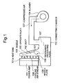
- Fig. 1 is a cross-sectional side view of a cooling apparatus according to the first embodiment of the present invention.
- compressed air 107 which is a kind of coolant fluid passes through a duct 102.
- the duct 102 has a nozzle plate 109 through which nozzles 105 are bored, and an inclined opposite plate 103 disposed oppositely to the nozzle plate 109.
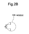
- the nozzle plate 109 forms a part of the duct 102 which communicates with a connecting chamber 110, and is provided with the nozzles 105 through which compressed air 107 is horizontally jetted as high-speed cooling air streams 106.
- the opposite plate 103 is disposed oppositely to the nozzle plate 109, forms a part of the duct 102 which communicates with the connecting chamber 110, and makes the current of compressed air 107, which is fed from the connecting chamber 110, tend to the nozzle plate 109.
- the cooling air streams 106 jetted are made to blow perpendicularly to an object to cool such as a heat sink 101a of a power amplifier 101 to compel the object to heat exchange.
- the exchanged heat capacity per unit time is thereby increased and so the object is cooled with a high cooling efficiency.
- the connecting chamber 110 communicates with the duct 102 for feeding compressed air 107.
- a blower 104 is for feeding compressed air 107 into the connecting chamber 110.
- the duct 102 is formed such that the opposite plate 103 inclines relatively to the nozzle plate 109 as shown in Fig. 1.
- the cooling air streams 106 jetted through a plurality of nozzles 105 are made to blow perpendicularly to the heat sink 101a to compel the heat sink 101a to heat exchange with the cooling air streams 106.
- the heat sink 101a is therefore cooled such that the temperature distribution becomes even throughout the heat sink 101a.
- the opposite plate 103 inclines relatively to the nozzle plate 109, there may be a nozzle 105 whose horizontal distance l from the inside surface of the opposite plate 103 coincides with a resonance distance l 0 of a specific frequency in the cooling air stream 106 jetted through the nozzle 105, as shown in Fig. 1. In that case, there is a fear that a resonance occurs to generate a whistle sound like the related art cooling apparatus.
- a resonance-preventing plate 108 with a certain thickness is attached to a certain area of the inside surface of the opposite plate 103 including a point (a point B in Fig. 2A) on a horizontal extension of the nozzle 105 as shown in Fig. 1.
- the horizontal distance l of any nozzle 105 from the inside surface of the opposite plate 103 thereby does not coincide with any resonance distance l 0 . Any resonance is thus prevented fundamentally and so no whistle sound is generated.
- metal such as iron and aluminum is suitable because its surface is hard to exfoliate even when highly frequent oscillations due to collision of the high-speed cooling air streams 106 against the surface of the resonance-preventing plate 108 are applied to the surface for a long time.
- material of the resonance-preventing plate 108 metal such as iron and aluminum is suitable because its surface is hard to exfoliate even when highly frequent oscillations due to collision of the high-speed cooling air streams 106 against the surface of the resonance-preventing plate 108 are applied to the surface for a long time.
- resin and a porous ceramic material may be used.
- the inclined opposite plate 103 is disposed oppositely to a plurality of nozzles 105 as shown in Fig. 2A, there are horizontal distances l according to combinations of the nozzles 105 and the opposite plate 103. As a result, there may be a nozzle 105 whose horizontal distance l from the opposite plate 103 coincides with a resonance distance l 0 of a peak frequency f 0 in the jet noise.
- the resonance-preventing plate 108 having a thickness of about several millimeters for example is attached to a certain area of the inside surface of the opposite plate 103 of the duct 102 including the point B as shown in Fig. 3 so that the horizontal distance l between the nozzle 105 and the resonance-preventing plate 108 does not coincide with the resonance distance l 0 .
- the position of attaching the resonance-preventing plate 108 and the thickness of the resonance-preventing plate 108 are suitably selected so that horizontal distances l do not coincide with resonance distances l 0 throughout the interior of the duct 102. In this manner, the generation of such a standing wave W in the duct 102 is prevented fundamentally and so no whistle sound is generated.
- a peak frequency f 0 [Hz] is expressed as follows where ⁇ represents Strouhal number, u represents the velocity [m/s] of a cooling air stream 106, and d represents the diameter [m] of each nozzle 105.
- f 0 ⁇ ⁇ (u/d)
- the resonance-preventing plate 108 is attached to a certain area of the inside surface of the opposite plate 103 so that the horizontal distance l of any nozzle 105 from the point at which a horizontal extension of the nozzle 105 intersects the inside surface of the opposite plate 103 or the resonance-preventing plate 1 does not coincide with a resonance distance l 0 .
- the generation of a standing wave W in the duct 102 is thereby prevented and so the generation of a whistle sound is prevented.
- Fig. 4 is a cross-sectional side view of a cooling apparatus according to the second embodiment of the present invention.
- the cooling apparatus shown in Fig. 4 is for cooling a plurality of power amplifiers 101.
- This cooling apparatus comprises a connecting chamber 110 which is extended to the left in Fig. 4.
- the power amplifiers 101 to be cooled are disposed in parallel on the connecting chamber 110.
- Ducts 102 each communicating with the connecting chamber 110 are disposed oppositely to the power amplifiers 101, respectively.
- the other structure of this apparatus is the same as that of Fig. 1.
- an object can be uniformly cooled by a simple structure because an inclined surface is disposed oppositely to a nozzle plate of a duct so as to make cooling streams of even quantities of a coolant throughout the vertical length of the duct.
- a whistle sound can be surely prevented because a resonance-preventing plate is provided in a duct so that no standing wave is generated even in case of the duct the transverse section of which changes in shape along a longitudinal axis of the duct.
Landscapes
- Cooling Or The Like Of Electrical Apparatus (AREA)
Abstract
Description
Claims (8)
- A cooling apparatus comprisinga duct including a nozzle plate through which a nozzle is bored so that a coolant is jetted through said nozzle and made to collide against an object to cool, and an inclined opposite plate which is disposed oppositely to said nozzle plate so as to make said coolant tend to said nozzle plate, anda resonance-preventing plate attached to an area of the inside surface of said opposite plate including the point at which an horizontal extension of said nozzle intersects the inside surface of said opposite plate so that the horizontal distance l [m] of said nozzle from the inside surface of said resonance-preventing plate is not equal toa resonance distance
- A cooling apparatus according to claim 1, further comprising a connecting chamber communicating with said duct to introduce said coolant into said duct.
- A cooling apparatus according to claim 1, further comprisinga connecting chamber communicating with said duct at one end of said connecting chamber to introduce said coolant into said duct, anda blower communicating with said connecting chamber at another end of said connecting chamber for feeding air into said duct as said coolant.
- A cooling apparatus according to claim 1, further comprisinga connecting chamber communicating with ducts including said duct to introduce said coolant into each of said ducts, andobjects to cool including said object to cool which are disposed oppositely to said ducts, respectively.
- A cooling apparatus according to claim 1, wherein air is used as said coolant.
- A cooling apparatus according to claim 1, wherein compressed air is used as said coolant.
- A cooling apparatus according to claim 1, wherein said object to cool is an electronic circuit.
- A cooling apparatus according to claim 1, wherein said object to cool is a power amplifier.
Applications Claiming Priority (3)
| Application Number | Priority Date | Filing Date | Title |
|---|---|---|---|
| JP29988397 | 1997-10-31 | ||
| JP9299883A JPH11135973A (en) | 1997-10-31 | 1997-10-31 | Cooling system |
| JP299883/97 | 1997-10-31 |
Publications (3)
| Publication Number | Publication Date |
|---|---|
| EP0914031A2 true EP0914031A2 (en) | 1999-05-06 |
| EP0914031A3 EP0914031A3 (en) | 1999-09-29 |
| EP0914031B1 EP0914031B1 (en) | 2003-12-17 |
Family
ID=17878106
Family Applications (1)
| Application Number | Title | Priority Date | Filing Date |
|---|---|---|---|
| EP98120573A Expired - Lifetime EP0914031B1 (en) | 1997-10-31 | 1998-10-30 | Cooling apparatus |
Country Status (4)
| Country | Link |
|---|---|
| US (1) | US6105661A (en) |
| EP (1) | EP0914031B1 (en) |
| JP (1) | JPH11135973A (en) |
| DE (1) | DE69820569T2 (en) |
Families Citing this family (4)
| Publication number | Priority date | Publication date | Assignee | Title |
|---|---|---|---|---|
| US6665185B1 (en) | 2002-10-09 | 2003-12-16 | Ltx Corporation | Apparatus and method for embedded fluid cooling in printed circuit boards |
| US8430644B2 (en) * | 2005-11-18 | 2013-04-30 | Nuventix, Inc. | Synthetic jet ejector for the thermal management of PCI cards |
| DE102006018709B3 (en) * | 2006-04-20 | 2007-10-11 | Nft Nanofiltertechnik Gmbh | Heat exchanger for cooling electronic component, has two stages arranged consecutively, where each stage has heat exchanging channel and guiding channels that are in flow connection with heat exchanging channels of next stages |
| KR200470868Y1 (en) * | 2012-12-07 | 2014-01-16 | (주)디포그 | The structure of the baffle plate mounted on the storage rack for telecommunications equipment |
Family Cites Families (22)
| Publication number | Priority date | Publication date | Assignee | Title |
|---|---|---|---|---|
| FR2157094A5 (en) * | 1971-10-18 | 1973-06-01 | Thomson Csf | |
| US4226279A (en) * | 1978-08-15 | 1980-10-07 | Foster Wheeler Energy Corporation | Method of suppressing formation of heat exchange fluid particles into standing waves |
| US4266602A (en) * | 1980-02-21 | 1981-05-12 | Westinghouse Electric Corp. | Heat exchanger for cooling electrical power apparatus |
| US4494171A (en) * | 1982-08-24 | 1985-01-15 | Sundstrand Corporation | Impingement cooling apparatus for heat liberating device |
| US4674004A (en) * | 1986-07-03 | 1987-06-16 | Burroughs Corporation | Parallel-flow air system for cooling electronic equipment |
| JPS6474798A (en) * | 1987-09-16 | 1989-03-20 | Nec Corp | Integrated type power amplifier |
| FR2621376B1 (en) * | 1987-10-01 | 1989-12-22 | Pont A Mousson | SEALING FOR TELESCOPIC LOCKED GASKETS |
| JPH01175298A (en) * | 1987-12-28 | 1989-07-11 | Nec Corp | Cooling structure of electronic circuit |
| JPH0242494A (en) * | 1988-08-02 | 1990-02-13 | Toshiba Corp | Voice input device |
| JP2708495B2 (en) * | 1988-09-19 | 1998-02-04 | 株式会社日立製作所 | Semiconductor cooling device |
| JPH031542A (en) * | 1989-05-29 | 1991-01-08 | Matsushita Electric Ind Co Ltd | Bipolar transistor manufacturing method |
| US5196989A (en) * | 1990-04-09 | 1993-03-23 | Trw Inc. | Rigid circuit board structure using impingement cooling |
| JP2811359B2 (en) * | 1990-08-13 | 1998-10-15 | 本田技研工業株式会社 | Emergency evacuation method in batch type surface treatment line |
| US5202816A (en) * | 1991-05-20 | 1993-04-13 | Dewilde Mark A | High density circuit board chassis cooling system |
| JPH0731028B2 (en) * | 1991-05-24 | 1995-04-10 | 株式会社ヒラノテクシード | Hot air supply method and heat dissipation device |
| JPH05136305A (en) * | 1991-11-08 | 1993-06-01 | Hitachi Ltd | Cooling device for heating element |
| CA2088821C (en) * | 1992-02-05 | 1999-09-07 | Hironobu Ikeda | Cooling structure for integrated circuit |
| US5428503A (en) * | 1992-03-24 | 1995-06-27 | Hitachi, Ltd. | Jet cooling apparatus for cooling electronic equipment and computer having the same mounted thereon |
| KR0160611B1 (en) * | 1992-05-22 | 1999-01-15 | 강진구 | Air conditioner noise prevention device |
| US5592363A (en) * | 1992-09-30 | 1997-01-07 | Hitachi, Ltd. | Electronic apparatus |
| JPH08153985A (en) * | 1994-11-28 | 1996-06-11 | Hitachi Ltd | Local cooling system for electronic devices |
| JPH0964569A (en) * | 1995-08-25 | 1997-03-07 | Hitachi Ltd | Electronic equipment |
-
1997
- 1997-10-31 JP JP9299883A patent/JPH11135973A/en active Pending
-
1998
- 1998-10-30 DE DE69820569T patent/DE69820569T2/en not_active Expired - Fee Related
- 1998-10-30 EP EP98120573A patent/EP0914031B1/en not_active Expired - Lifetime
- 1998-11-02 US US09/184,222 patent/US6105661A/en not_active Expired - Fee Related
Also Published As
| Publication number | Publication date |
|---|---|
| JPH11135973A (en) | 1999-05-21 |
| US6105661A (en) | 2000-08-22 |
| DE69820569D1 (en) | 2004-01-29 |
| EP0914031A3 (en) | 1999-09-29 |
| EP0914031B1 (en) | 2003-12-17 |
| DE69820569T2 (en) | 2004-09-23 |
Similar Documents
| Publication | Publication Date | Title |
|---|---|---|
| US7010930B2 (en) | Method and system for cooling high power density devices | |
| EP0984662B1 (en) | Waveguide electroacoustical transducing | |
| EP0914031B1 (en) | Cooling apparatus | |
| EP1441863A4 (en) | Fire suppression using water mist with ultrafine size droplets | |
| JP2001526841A (en) | Electronic component cooling device | |
| JP2000508988A (en) | Car washing equipment | |
| US4417295A (en) | Air jet powered cooling system for electronic assemblies | |
| JP2853481B2 (en) | Semiconductor element cooling structure | |
| CA2088821A1 (en) | Cooling structure for integrated circuit | |
| WO2014199705A1 (en) | Device for continuous generation of single-component cryogenic fine solid particles, and method for continuous generation of single component cryogenic fine solid particles | |
| SE9302062L (en) | Method and apparatus for the formation of snow | |
| JPH0311546B2 (en) | ||
| JP2001207214A (en) | Rapid cooling method for heated metallic object | |
| AU754344B2 (en) | A method and an apparatus for air-cooling | |
| US5110036A (en) | Method and apparatus for solder leveling of printed circuit boards | |
| JP2869620B2 (en) | Spray nozzle for cleaning | |
| JP2747156B2 (en) | Immersion jet cooling heat sink | |
| KR20060036249A (en) | Chiller | |
| CA2001721A1 (en) | Method and arrangement for an enforced heat transmission between bodies and gases | |
| JP2000049480A (en) | Heat sink cooling device | |
| JPH02233166A (en) | Spray apparatus | |
| EP0382397A1 (en) | Cooling head for integrated circuit | |
| JP2531459B2 (en) | Integrated circuit cooling structure | |
| JP2003142640A (en) | Heat dissipation structure of semiconductor device | |
| CN222395976U (en) | An attenuator with high heat dissipation performance |
Legal Events
| Date | Code | Title | Description |
|---|---|---|---|
| PUAI | Public reference made under article 153(3) epc to a published international application that has entered the european phase |
Free format text: ORIGINAL CODE: 0009012 |
|
| AK | Designated contracting states |
Kind code of ref document: A2 Designated state(s): DE FR GB |
|
| AX | Request for extension of the european patent |
Free format text: AL;LT;LV;MK;RO;SI |
|
| PUAL | Search report despatched |
Free format text: ORIGINAL CODE: 0009013 |
|
| AK | Designated contracting states |
Kind code of ref document: A3 Designated state(s): AT BE CH CY DE DK ES FI FR GB GR IE IT LI LU MC NL PT SE |
|
| AX | Request for extension of the european patent |
Free format text: AL;LT;LV;MK;RO;SI |
|
| 17P | Request for examination filed |
Effective date: 19990827 |
|
| AKX | Designation fees paid |
Free format text: DE FR GB |
|
| GRAH | Despatch of communication of intention to grant a patent |
Free format text: ORIGINAL CODE: EPIDOS IGRA |
|
| GRAS | Grant fee paid |
Free format text: ORIGINAL CODE: EPIDOSNIGR3 |
|
| GRAA | (expected) grant |
Free format text: ORIGINAL CODE: 0009210 |
|
| AK | Designated contracting states |
Kind code of ref document: B1 Designated state(s): DE FR GB |
|
| REG | Reference to a national code |
Ref country code: GB Ref legal event code: FG4D |
|
| REF | Corresponds to: |
Ref document number: 69820569 Country of ref document: DE Date of ref document: 20040129 Kind code of ref document: P |
|
| ET | Fr: translation filed | ||
| PLBE | No opposition filed within time limit |
Free format text: ORIGINAL CODE: 0009261 |
|
| STAA | Information on the status of an ep patent application or granted ep patent |
Free format text: STATUS: NO OPPOSITION FILED WITHIN TIME LIMIT |
|
| 26N | No opposition filed |
Effective date: 20040920 |
|
| PGFP | Annual fee paid to national office [announced via postgrant information from national office to epo] |
Ref country code: GB Payment date: 20061025 Year of fee payment: 9 |
|
| PGFP | Annual fee paid to national office [announced via postgrant information from national office to epo] |
Ref country code: DE Payment date: 20061026 Year of fee payment: 9 |
|
| GBPC | Gb: european patent ceased through non-payment of renewal fee |
Effective date: 20071030 |
|
| PG25 | Lapsed in a contracting state [announced via postgrant information from national office to epo] |
Ref country code: DE Free format text: LAPSE BECAUSE OF NON-PAYMENT OF DUE FEES Effective date: 20080501 |
|
| REG | Reference to a national code |
Ref country code: FR Ref legal event code: ST Effective date: 20080630 |
|
| PGFP | Annual fee paid to national office [announced via postgrant information from national office to epo] |
Ref country code: FR Payment date: 20061010 Year of fee payment: 9 |
|
| PG25 | Lapsed in a contracting state [announced via postgrant information from national office to epo] |
Ref country code: GB Free format text: LAPSE BECAUSE OF NON-PAYMENT OF DUE FEES Effective date: 20071030 |
|
| PG25 | Lapsed in a contracting state [announced via postgrant information from national office to epo] |
Ref country code: FR Free format text: LAPSE BECAUSE OF NON-PAYMENT OF DUE FEES Effective date: 20071031 |