EP0913677A1 - Pressure detection device - Google Patents
Pressure detection device Download PDFInfo
- Publication number
- EP0913677A1 EP0913677A1 EP98120323A EP98120323A EP0913677A1 EP 0913677 A1 EP0913677 A1 EP 0913677A1 EP 98120323 A EP98120323 A EP 98120323A EP 98120323 A EP98120323 A EP 98120323A EP 0913677 A1 EP0913677 A1 EP 0913677A1
- Authority
- EP
- European Patent Office
- Prior art keywords
- detection device
- pressure detection
- terminal
- pressure
- electro
- Prior art date
- Legal status (The legal status is an assumption and is not a legal conclusion. Google has not performed a legal analysis and makes no representation as to the accuracy of the status listed.)
- Granted
Links
Images


Classifications
-
- G—PHYSICS
- G01—MEASURING; TESTING
- G01L—MEASURING FORCE, STRESS, TORQUE, WORK, MECHANICAL POWER, MECHANICAL EFFICIENCY, OR FLUID PRESSURE
- G01L19/00—Details of, or accessories for, apparatus for measuring steady or quasi-steady pressure of a fluent medium insofar as such details or accessories are not special to particular types of pressure gauges
- G01L19/0092—Pressure sensor associated with other sensors, e.g. for measuring acceleration or temperature
-
- G—PHYSICS
- G01—MEASURING; TESTING
- G01L—MEASURING FORCE, STRESS, TORQUE, WORK, MECHANICAL POWER, MECHANICAL EFFICIENCY, OR FLUID PRESSURE
- G01L9/00—Measuring steady of quasi-steady pressure of fluid or fluent solid material by electric or magnetic pressure-sensitive elements; Transmitting or indicating the displacement of mechanical pressure-sensitive elements, used to measure the steady or quasi-steady pressure of a fluid or fluent solid material, by electric or magnetic means
- G01L9/0089—Transmitting or indicating the displacement of pistons by electrical, electromechanical, magnetic or electromagnetic means
-
- H—ELECTRICITY
- H01—ELECTRIC ELEMENTS
- H01H—ELECTRIC SWITCHES; RELAYS; SELECTORS; EMERGENCY PROTECTIVE DEVICES
- H01H35/00—Switches operated by change of a physical condition
- H01H35/24—Switches operated by change of fluid pressure, by fluid pressure waves, or by change of fluid flow
- H01H35/38—Switches operated by change of fluid pressure, by fluid pressure waves, or by change of fluid flow actuated by piston and cylinder
-
- H—ELECTRICITY
- H01—ELECTRIC ELEMENTS
- H01H—ELECTRIC SWITCHES; RELAYS; SELECTORS; EMERGENCY PROTECTIVE DEVICES
- H01H3/00—Mechanisms for operating contacts
- H01H3/02—Operating parts, i.e. for operating driving mechanism by a mechanical force external to the switch
- H01H3/0213—Combined operation of electric switch and variable impedance, e.g. resistor, capacitor
Definitions
- the present invention relates to a pressure detection device used for detecting a pressure increase in a hydraulic apparatus, more particularly, to a pressure detection device in which a functional material changing an electric resistance corresponding to a load pressure operated thereto is provided between two electrodes thereof.
- a hydraulic pump In a hydraulic power steering apparatus used in an automobile or the like, a hydraulic pump is generally driven by an engine of the automobile, and operation fluid discharged from the hydraulic pump is supplied to the power steering apparatus, so as to assist the driver's steering operation.
- the conventional automobile employs a so-called idle-up mechanism in which a pressure switch is provided for detecting an increase in the load pressure of the hydraulic pump so as to operate the idle-up mechanism while the engine is running at the idle rotational speed.
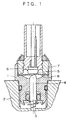
- FIG. 1 shows an example of such a pressure switch, as disclosed in Japanese Patent Laid Open Publication No. 9-147708.
- numeral 1 denotes a switch housing, which is attached to a pressure introduction passage 3 formed in a pump housing.
- a piston 4 is disposed so as to be axially movable according to an increase of the load pressure led from the pressure introduction passage 3.
- a terminal 5 is arranged to be defined as one of a pair of electrode contacts, which is supported by a support ring 7 via a resin 6 serving as an electric insulator.
- a disc spring 8 is provided to be defined as the other electrode contact, which comes into contact with the terminal 5 when being deformed by the pressure force of the piston 4.
- the disc spring 8 is supported by the support ring 7 and the switch housing 1, and is grounded by electrically communicating from the switch housing 1 to the pump housing 2.
- the conventional pressure switch has such a function that operates in an ON-OFF manner where it is turned on when the load pressure of the hydraulic pump exceeds a predetermined pressure. Therefore, it is impossible to continuously control the engine so as to change the rotational speed thereof according to the load pressure of the hydraulic pump.
- the engine is controlled so as to increase the idle rotational speed in correspondence with a maximum load of the hydraulic pump when the ON-operation of the pressure switch is carried out, so that the energy consumption of the automobile is increased.
- the pressure sensor In the hydraulic power steering apparatus, it may be thought to use a pressure sensor to continuously change the idle rotational speed of the engine according to the load pressure of the hydraulic pump.
- the pressure sensor has a complex construction and is expensive compared with the pressure switch as described above.
- an element consisting of the pressure sensor has a low characteristic in linearity, so that it requires an electric circuit for compensating the output thereof, whereby it is more expensive. This is a reason why the pressure sensor is not used generally.
- an object of the present invention is to solve the above-described problem and to provide a pressure detection device in which an electric-functional member is provided for detecting a load pressure of a hydraulic pump with simple construction and low cost.
- Another object of the present invention is to provide a pressure detection device which is capable of changing its electric resistance characteristic by changing a shape of an electro-functional member.
- Further object of the present invention is to provide a pressure detection device which is capable of compensating the output signal thereof with an ambient temperature detection element.
- a pressure detection device includes an electrically conductive device housing which has an accommodation bore extending inward from one end of the device housing and a slide bore extending between the accommodation bore and the other end of the device housing.
- a piston is slidably disposed within the slide bore and adopted to receive a pressure, and a terminal serving as one electric contact is fixed to the accommodation bore via an electrical insulator.
- a disk spring serving as the other electric contact deforms due to a pressing force of the piston and coming in contact with the terminal.
- the pressure detection device further comprises an electro-functional member attached to either the terminal or the disk spring in which the electro-functional member is changeable its electric resistance due to an impressed pressing force acting thereon.
- the output signal of the electro-functional member changes corresponding to the load pressure acting thereon, so that the pressure detection device can detect the load pressure.
- a notch and/or a chamfer is provided on the electro-functional member for changing its electric resistance characteristic. Therefore, it is possible to change the electric resistance characteristic of the pressure detection device without adding another electric circuit or device.
- a thermistor is provided in the pressure detection device for detecting an ambient temperature thereof, so that it is possible to compensate the output signal of the electro-functional member based upon the ambient temperature, whereby the construction of the pressure detection device can be simplified and the assemble cost thereof can be diminished.
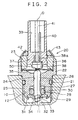
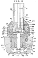
- FIG. 2 shows a sectional view of a pressure detection device according to the first embodiment of the present invention.
- the left side of a center axis O depicts a state in which no load pressure acts on the pressure detection device, while the right side of the center axis O depicts a state in which a certain load pressure acts on the pressure detection device.
- numeral 10 denotes a pump housing of a hydraulic pump in which a pressure introduction passage 11 is formed.
- a pressure detection device 20 according to the first embodiment of the present invention is screwed into a threaded hole 12 formed at the opening end of the pressure introduction passage 11, with a seal ring 21 being interposed between the threaded hole 12 and the pump housing 10 so as to secure in a fluid-tight manner.
- a housing 22 of the pressure detection device 20 has an accommodation bore 23 that has a large diameter and extend inward from one end of the housing 22, as well as a slide bore 24 that has a smaller diameter and extends between the accommodation bore 23 and the other end of the housing 22.
- On the outer circumferential surface of the other end of the housing 22 is formed a threaded portion 25 for screw engagement with the threaded hole 12 of the pump housing 10.
- a piston 26 is slidably inserted into the slide bore 24 such that the tip end of the piston 26 projects into the accommodation bore 23, which shape takes in the form of a half-spherical surface.
- a depression 30 is formed at the opening end (lower end in FIG. 2) of the slide bore 24 so as to accommodate therein a Teflon ring 27, an O-ring 28 and an engagement member 29, in this order with respect to the direction toward the pressure introduction passage 11.
- the outer circumferential surface of the piston 26 is in close contact with the inner circumferential surface of the O-ring 28.
- a thin-wall portion 31 of the lower end of the housing 22, which end corresponds to the depression 30, is deformed inward through caulking or crimping, so that the Teflon ring 27, the O-ring 28 and the engagement member 29 are prevented from moving axially.
- the piston 26 has a smaller diameter portion 32 at its one end which faces the pressure introduction passage 11. Movement of the piston 26 toward the pressure introduction passage 11 is limited by engagement between the engagement member 29 and a stepped portion 33 formed at the root of the smaller diameter portion 32. Moreover, a stopper ring 34 is attached to the outer circumferential of the smaller diameter portion 32. Engagement of between the stopper ring 34 and the engagement member 29 prevents the piston 26 from excessively moving toward the accommodation bore 23 even when an abnormal pressure acts on the piston 26.
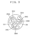
- a disk spring 35 having a shape shown in FIG. 3.
- the disk spring 35 is held at its outer circumferential edge by a holding ring 36, which is press-fit into the accommodation bore 36.
- the disk spring 35 is formed of metallic thin plate and has three cut portions 35A which extend from the outer edge toward the center of the disk spring 35, so that there is formed a center portion 35B which is supported by flexible portions 35C formed by the cut portions 35A.
- the flexible portions 35C deform, and the center portion 35B moves accordingly.
- the disk spring 35 is grounded to the vehicle body via the housing 22 and the pump housing 10.
- a contact member 50 made of an electro-functional material having an electric resistance characteristics which changes its electric resistance corresponding to a mechanical strain applied thereon.
- This electro-functional material has such a characteristic that its electric resistance is large in a case that no mechanical strain acts thereon, while its electric resistance becomes to be smaller gradually in accordance with the mechanical strain acting on the electro-functional material, wherein the strain is gradually larger.
- the sensing member i.e., electro-functional material
- the sensing member as disclosed in Japanese Patent Laid Open Publication is secured as the contact member 50 onto the center portion 35B of the disk spring 35.
- the flexible portions 35C are deformed when pressure applied to the center portion 35B excesses the predetermined level, so that the disk spring 35 is brought into contact with the terminal 38 via the contact member 50, whereby the terminal 38 is grounded to the pump housing 10 through the housing 22 of the pressure detection device 20.
- the terminal 38 Before the holding ring 36 is press-fit into the housing 22, the terminal 38 is placed within and attached to the holding ring 36 via a support 37 made of resin serving as an insulating material.
- the support 37 extends upward in FIG. 2 so as to form an attachment bore 39 into which an unillustrated connector is inserted.
- a connection terminal 40 is connected to a shaft portion 38a of the terminal 38 and projects into the attachment bore 39 for engagement with the unillustrated connector.
- numeral 41 denotes a guide groove for guiding the connector within the attachment bore 39 when the connector is inserted into the attachment bore 39. Further, an unillustrated power supply is connected to the connection terminal 40 so as to detect an electric resistance between the pair of electrodes (i.e., the disk spring 35 and the terminal 38).
- Numeral 42 denotes an O-ring made of rubber and having a circular cross section.
- the O-ring 42 is placed within the opening portion of the accommodation bore 23 such that it sits on the upper end surface of the holding ring 36 and is in close contact with the outer circumference of the support 37.
- a thin wall end portion 43 of the housing 22, which surrounds the accommodation bore 23, is deformed inward through caulking so as to elastically deform the O-ring 42, so that the opening portion of the accommodation bore 43 is sealed.
- the holding ring 36 is fixed to the housing 22 via the O-ring 42, so that the disk spring 35 is held in place.
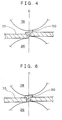
- the left side of the center axis O depicts a state in which no load pressure from the pressure introduction passage 11 acts on the piston 26, while the right side of the center axis O depicts a state in which a certain load pressure acts thereon.
- the end portion of the terminal 38 faces with the contact member 50 provided on the center portion 35B of the disk spring 35 via a slight clearance. In such a case, the end portion of the terminal 38 is brought into contact with the contact member 50 due to a slight elastic deformation of the flexible portions 35C.
- the left side of the center axis O shown in FIG. 4 depicts a state of the terminal 38, the disk spring 35 and the contact member 50 in which the steering wheel is not operated.
- the load pressure is not raised, so that the flexible portions 35C of the disk spring 35 is not deformed, whereby the clearance between the end portion of the terminal 38 and the contact member 50 is maintained. Therefore, the terminal 38 is not electrically communicated with the disk spring 35.
- the load pressure of the hydraulic pump increases due to this operation, and acts on the lower end of the piston 26 through the pressure introduction passage 11, resulting in coming the piston 26 into contact with the disk spring 35. Further, the load pressure increases over the spring force of the disk spring 35, so that the flexible portions 35C are deformed by the pressing force of the piston 26, whereby the contact member 50 contacts with the terminal 38. As a result of contact, the terminal 38 is electrically communicated with the disk spring 35.
- the right side of the center axis O in FIG. 4 shows a state of the terminal 38, the disk spring 35 and the contact member 50 in the stationary steering operation.
- the contact member 50 consists of a electro-functional material (ceramics) having an electric resistance characteristic that changes its resistance according to the mechanical strain applied thereon, so that the electric resistance between the terminal 38 and the disk spring 35 changes in correspondence with the load pressure of the hydraulic pump. Detecting the electric resistance between the terminal 38 and the disk spring 35, the detected value of the electric resistance is output to an engine control apparatus (not shown). Therefore, it is possible to control the engine so as to continuously change its idle rotational speed in accordance with the load pressure of the hydraulic pump.
- FIG. 5 is a graph showing a relationship between the detected electric resistance and the load pressure of the hydraulic pump in the pressure detection device 20 according to the fist embodiment.
- the contact member 50 comes into contact with the terminal 38 initially.
- the electric resistance is large and however, it becomes to be smaller due to the increase of the mechanical strain in the contact member 50 and of contact area between the terminal 38 and the contact member 50 as the load pressure of the hydraulic pump increases. Therefore, sensitive area can be obtained, as shown the area B in FIG. 5.
- the deformation of the contact member 50 is saturated, as shown by the right side of the center axis O in FIG. 4. Therefore, the area C proportional to the load pressure can be obtained due to the mechanical strain of the contact member 50.
- the idle rotational speed of the engine corresponding to the load pressure of the hydraulic pump. Further, the energy consumption can be eliminated in non-steering operation with a simple construction and low cost.
- the contact member 50 is in a slight contact with the terminal 38 in no load pressure, i.e., the steering wheel is not operated.
- the second embodiment is different form the first embodiment in that the pair of electrodes (the contact member 50 and the terminal 38) are contacted with a slight contact area.
- a right side of the center axis O in FIG. 6 depicts a state in which the load pressure acts on the contact member 50 through the piston 26.
- FIG. 7 is a graph showing a relationship between an electric resistance of the contact member 50 and the terminal 38 and the load pressure, according to a contact detection device of the second embodiment.
- the contact member 50 is a slight contact state with the terminal 38.
- sensitive area can be obtained due to the increase of the mechanical strain in the contact member 50 and of contact area between the terminal 38 and the contact member 50 as the load pressure of the hydraulic pump increases, as shown the area D in FIG. 7.
- the deformation of the contact member 50 is saturated, so that the area E proportional to the load pressure can be obtained due to the mechanical strain of the contact member 50.
- the contact member is provided on the disk spring 35, but it may be provided on the terminal 38.
- FIGS. 9-12 A third embodiment according to the present invention will be now explained with reference to FIGS. 9-12.
- the feature of the third embodiment is to provide a notch on the contact member 50 to improve linearity of an output signal thereof, and to provide a thermistor 60 for a temperature compensation in the contact member 50.
- the third embodiment of the present invention is different from the second embodiment thereof in that a thermistor 60 is provided in a pressure detection device 20 and in a form of the contact member 50 attached to the terminal 38.
- the other portions of the third embodiment are the same as the first embodiment, and therefore the same portion is referred with the same reference number, and the detail of the same portion is omitted.
- the thermistor for detecting the temperature of the contact member 50 for compensation is provided in the support 37 made of resin serving as an insulating material, in which a signal line 62 of the thermistor 60 is connected to an illustrated compensation device through a pore 37a formed in the support 37, as shown in FIG. 8. Further, the contact member 50 is provided in a depression 38b formed in the terminal 38, into which the contact member 50 is joined by a solder 52 or the like.
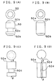
- FIG. 9(A) shows a top plan view and a front view of the contact member 50 having a notch.
- chamfers 50b In a top end and bottom end surfaces of the contact member 50 is formed chamfers 50b, and also an annular groove 50c is formed in a middle portion thereof. Since the chamfers 50b and the annular groove 50c are formed on the contact member 50, the mechanical strain is concentrated thereto because of diminishing of sectional area.
- the mechanical strain due to the external force is large compared with the other portion, so that the electric resistance characteristic to the load pressure is changed, whereby it can be obtained to improve the linearity in the electric resistance characteristic to the load pressure as a whole of the contact member 50.
- FIG. 9(B) shows the contact member 50 ⁇ in which the chamfers 50b are only formed, and also the annular groove 50c is only formed in FIG. 9(C).
- a vertical groove 50d is formed in FIGS. 9(C) and 9(D).
- ⁇ represents a direction of the external force.
- a notch 50e is formed in FIG. 9(E)
- a hole 50f is formed by a drill in FIG. 9(F).
- a penetration hole 50g is formed in FIG. 9(G).
- the contact member 50 takes in the form of cylinder basically, and the penetration hole 50g and the vertical groove 50d are further formed.
- the notch of the contact member 50 is formed when the above-described sensing material (ceramic) is burned, and also it is possible to form it after burning. Further, it is possible to partially form a portion of the notch and to form the remaining thereof after burning.
- This embodiment represents to form the chamfers 50b and the annular groove 50c on the contact member 50, and however it is possible to use a combination of various notches. Further, this embodiment represents to compensate electric resistance of the contact member 50 by using various notches, but it is possible to compensate it by changing specific resistivity or gauging rate.
- a terminal resistance of the contact member 50 is represented as R S .
- One of terminals of the contact member 50 (R S ) is serially connected to a power supply supplying 5V through a regulation resistance R T , while the other terminal thereof is grounded.
- R S a value of the resistance R S of the contact member 50 changes corresponding to the pressing force acting the contact member 50, so that an output voltage that divides the power supply voltage 5V by the regulation resistance R T is generated as a pressure output signal corresponding to the value of the resistance R S .
- one of terminals of the thermistor 60 is serially connected to the power supply through a regulation resistance R O , while the other terminal thereof is grounded.
- the thermistor 60 changes its resistance value corresponding to an ambient temperature (i.e., the temperature of the contact member 50), so that the other output voltage that divides the power supply voltage 5V by the regulation resistance R O is generated as a temperature compensation signal corresponding to the value of the resistance of the thermistor 50.
- the pressure output signal and the temperature compensation signal are output to an unillustrated engine control unit (referred to as "EGC” hereinafter) after being converted from analog signal to digital signal (A/D convert).
- the operation in the third embodiment is similar to that in the second embodiment. However, it differs from the operation in the second embodiment in that the thermistor 60 (ambient temperature detection element) is provided in the pressure detection device 20.
- the load pressure does not raise, so that the disk spring 35 is not deformed.
- the external force does not act on the contact member 50, so that high resistance value is maintained, whereby the high voltage is output to the EGC as the pressure output signal.
- the EGC keeps the engine rotational speed at a predetermined level corresponding to the pressure output signal.
- the load pressure led from the pressure introduction passage 11 acts on the one end of the piston 26 with increasing of the load pressure of the hydraulic pump, resulting in deforming the disk spring 35.
- the external force acts on the contact member 50, so that the electric resistance value in the contact member 50 is decreased according to the impressed external force (the load pressure of the hydraulic pump).
- the terminal voltage of the contact member 50 corresponding to the electric resistance value thereof is output to the EGC as a pressure output signal.
- the temperature compensation signal (the temperature of the contact member 50) from the thermistor 60 is also output to the EGC.
- the value of the pressure output signal is compensated in the EGC by the temperature compensation signal, the engine is continuously controlled so as to perform the idle rotational speed in correspondence with the load pressure of the hydraulic pump.
- the idle rotational speed of the engine is adapted according the load pressure of the hydraulic pump, so that fuel consumption can be optimized.
- the pressure output signal is compensated by the ambient temperature, the idle rotational speed can be accurately controlled.
- a pressure detection device for detecting an increase of pressure acting thereon includes an electrically conductive device housing which has an accommodation bore extending inward from one end of the device housing and a slide bore extending between the accommodation bore and the other end of the device housing.
- a piston is slidably disposed within the slide bore and adopted to receive a pressure, and a terminal serving as one electric contact is fixed to the accommodation bore via an electrical insulator.
- a disk spring serving as the other electric contact deforms due to a pressing force of the piston and coming in contact with the terminal.
- the pressure detection device further comprises an electro-functional member attached to either the terminal or the disk spring in which the electro-functional member is changeable its electric resistance due to an impressed pressing force acting thereon. Further, at least one of a notch and a chamfer is provided on the electro-functional member for changing its electric resistance characteristic.
Abstract
Description
- The present invention relates to a pressure detection device used for detecting a pressure increase in a hydraulic apparatus, more particularly, to a pressure detection device in which a functional material changing an electric resistance corresponding to a load pressure operated thereto is provided between two electrodes thereof.
- In a hydraulic power steering apparatus used in an automobile or the like, a hydraulic pump is generally driven by an engine of the automobile, and operation fluid discharged from the hydraulic pump is supplied to the power steering apparatus, so as to assist the driver's steering operation.
- In such a hydraulic power steering apparatus, when a steering operation is carried out while the automobile is stopped, i.e., the engine is running at its idle rotational speed (hereinafter referred to as "stationary steering operation"), the load pressure in the hydraulic pump increases, whereby the engine may be stalled.
- In order to solve this problem, the conventional automobile employs a so-called idle-up mechanism in which a pressure switch is provided for detecting an increase in the load pressure of the hydraulic pump so as to operate the idle-up mechanism while the engine is running at the idle rotational speed.
- FIG. 1 shows an example of such a pressure switch, as disclosed in Japanese Patent Laid Open Publication No. 9-147708. In FIG. 1, numeral 1 denotes a switch housing, which is attached to a
pressure introduction passage 3 formed in a pump housing. In the switch housing 1, apiston 4 is disposed so as to be axially movable according to an increase of the load pressure led from thepressure introduction passage 3. In an upper portion of thepiston 4, aterminal 5 is arranged to be defined as one of a pair of electrode contacts, which is supported by asupport ring 7 via aresin 6 serving as an electric insulator. - Between the
terminal 5 and thepiston 4, adisc spring 8 is provided to be defined as the other electrode contact, which comes into contact with theterminal 5 when being deformed by the pressure force of thepiston 4. Thedisc spring 8 is supported by thesupport ring 7 and the switch housing 1, and is grounded by electrically communicating from the switch housing 1 to thepump housing 2. - In the pressure switch as configured above, when the load pressure in the hydraulic pump is raised due to the stationary steering operation while the engine is running at the idle rotational speed, the pressure increase acts onto the
piston 4, whereby thepiston 4 is slid against the spring force of thedisc spring 8. With this slide movement of thepiston 4, thedisc spring 8 is deformed and then is electrically brought into contact with theterminal 5, so that the pump housing 1 is electrically communicated with theterminal 5, whereby the pressure switch generates an electric signal for the idle-up operation to a control apparatus. - However, the conventional pressure switch has such a function that operates in an ON-OFF manner where it is turned on when the load pressure of the hydraulic pump exceeds a predetermined pressure. Therefore, it is impossible to continuously control the engine so as to change the rotational speed thereof according to the load pressure of the hydraulic pump. In the automobile providing such a pressure switch, the engine is controlled so as to increase the idle rotational speed in correspondence with a maximum load of the hydraulic pump when the ON-operation of the pressure switch is carried out, so that the energy consumption of the automobile is increased.
- In the hydraulic power steering apparatus, it may be thought to use a pressure sensor to continuously change the idle rotational speed of the engine according to the load pressure of the hydraulic pump. However, the pressure sensor has a complex construction and is expensive compared with the pressure switch as described above. Further, an element consisting of the pressure sensor has a low characteristic in linearity, so that it requires an electric circuit for compensating the output thereof, whereby it is more expensive. This is a reason why the pressure sensor is not used generally.
- Accordingly, an object of the present invention is to solve the above-described problem and to provide a pressure detection device in which an electric-functional member is provided for detecting a load pressure of a hydraulic pump with simple construction and low cost.
- Another object of the present invention is to provide a pressure detection device which is capable of changing its electric resistance characteristic by changing a shape of an electro-functional member.
- Further object of the present invention is to provide a pressure detection device which is capable of compensating the output signal thereof with an ambient temperature detection element.
- Briefly, a pressure detection device according to the present invention includes an electrically conductive device housing which has an accommodation bore extending inward from one end of the device housing and a slide bore extending between the accommodation bore and the other end of the device housing. A piston is slidably disposed within the slide bore and adopted to receive a pressure, and a terminal serving as one electric contact is fixed to the accommodation bore via an electrical insulator. A disk spring serving as the other electric contact deforms due to a pressing force of the piston and coming in contact with the terminal. The pressure detection device further comprises an electro-functional member attached to either the terminal or the disk spring in which the electro-functional member is changeable its electric resistance due to an impressed pressing force acting thereon.
- With this construction, the output signal of the electro-functional member changes corresponding to the load pressure acting thereon, so that the pressure detection device can detect the load pressure.
- Further, a notch and/or a chamfer is provided on the electro-functional member for changing its electric resistance characteristic. Therefore, it is possible to change the electric resistance characteristic of the pressure detection device without adding another electric circuit or device.
- Furthermore, a thermistor is provided in the pressure detection device for detecting an ambient temperature thereof, so that it is possible to compensate the output signal of the electro-functional member based upon the ambient temperature, whereby the construction of the pressure detection device can be simplified and the assemble cost thereof can be diminished.
- Various other objects, features and many of the attendant advantages of the present invention will be readily appreciated as the same becomes better understood by reference to the following detailed description of the preferred embodiment when considered in connection with the accompanying drawings, in which;
- FIG. 1 is a sectional view showing a conventional pressure switch;
- FIG. 2 is a sectional view showing a pressure detection device according to a first embodiment of the present invention;
- FIG. 3 is a top plan view showing a disk spring of the first embodiment;
- FIG. 4 is an enlarged sectional view of FIG. 2;
- FIG. 5 is a graph showing a relationship between an electric resistance of a contact member and a load pressure acting thereon according to the first embodiment of the present invention;
- FIG. 6 is an enlarged sectional view according to a second embodiment of the present invention;
- FIG. 7 is a graph showing a relationship between an electric resistance of a contact member and a load pressure acting thereon according to the second embodiment of the present invention;
- FIG. 8 is a sectional view showing a contact detection device according to a third embodiment of the present invention;
- FIGS. 9(A)-9(H) are top and front views showing various contact members according to the third embodiment of the present invention; and
- FIG. 10 is a circuit diagram for compensating a detected signal from the contact member based upon an ambient temperature thereof, according to the third embodiment of the present invention.
-
- The present invention will be described hereinafter with reference to the accompanying drawings.
- A first embodiment of the present invention will be described hereinafter with reference to FIGS. 2-4. FIG. 2 shows a sectional view of a pressure detection device according to the first embodiment of the present invention. In FIG. 2, the left side of a center axis O depicts a state in which no load pressure acts on the pressure detection device, while the right side of the center axis O depicts a state in which a certain load pressure acts on the pressure detection device.
- In FIG. 2,
numeral 10 denotes a pump housing of a hydraulic pump in which apressure introduction passage 11 is formed. Apressure detection device 20 according to the first embodiment of the present invention is screwed into a threadedhole 12 formed at the opening end of thepressure introduction passage 11, with aseal ring 21 being interposed between the threadedhole 12 and thepump housing 10 so as to secure in a fluid-tight manner. - A
housing 22 of thepressure detection device 20 has an accommodation bore 23 that has a large diameter and extend inward from one end of thehousing 22, as well as aslide bore 24 that has a smaller diameter and extends between the accommodation bore 23 and the other end of thehousing 22. On the outer circumferential surface of the other end of thehousing 22 is formed a threadedportion 25 for screw engagement with the threadedhole 12 of thepump housing 10. - A
piston 26 is slidably inserted into theslide bore 24 such that the tip end of thepiston 26 projects into the accommodation bore 23, which shape takes in the form of a half-spherical surface. Adepression 30 is formed at the opening end (lower end in FIG. 2) of the slide bore 24 so as to accommodate therein a Teflonring 27, an O-ring 28 and anengagement member 29, in this order with respect to the direction toward thepressure introduction passage 11. The outer circumferential surface of thepiston 26 is in close contact with the inner circumferential surface of the O-ring 28. A thin-wall portion 31 of the lower end of thehousing 22, which end corresponds to thedepression 30, is deformed inward through caulking or crimping, so that the Teflonring 27, the O-ring 28 and theengagement member 29 are prevented from moving axially. - The
piston 26 has asmaller diameter portion 32 at its one end which faces thepressure introduction passage 11. Movement of thepiston 26 toward thepressure introduction passage 11 is limited by engagement between theengagement member 29 and astepped portion 33 formed at the root of thesmaller diameter portion 32. Moreover, astopper ring 34 is attached to the outer circumferential of thesmaller diameter portion 32. Engagement of between thestopper ring 34 and theengagement member 29 prevents thepiston 26 from excessively moving toward the accommodation bore 23 even when an abnormal pressure acts on thepiston 26. - At the bottom of the
accommodation bore 23 is disposed adisk spring 35 having a shape shown in FIG. 3. Thedisk spring 35 is held at its outer circumferential edge by aholding ring 36, which is press-fit into the accommodation bore 36. Thedisk spring 35 is formed of metallic thin plate and has threecut portions 35A which extend from the outer edge toward the center of thedisk spring 35, so that there is formed acenter portion 35B which is supported byflexible portions 35C formed by thecut portions 35A. When a force greater than a predetermined level is applied onto thecenter portion 35B, theflexible portions 35C deform, and thecenter portion 35B moves accordingly. As described above, thedisk spring 35 is grounded to the vehicle body via thehousing 22 and thepump housing 10. - As shown in FIGS. 2 and 3, on the
center portion 35B is joined acontact member 50 made of an electro-functional material having an electric resistance characteristics which changes its electric resistance corresponding to a mechanical strain applied thereon. This electro-functional material has such a characteristic that its electric resistance is large in a case that no mechanical strain acts thereon, while its electric resistance becomes to be smaller gradually in accordance with the mechanical strain acting on the electro-functional material, wherein the strain is gradually larger. - It is preferred to that described in Japanese Patent Laid Open Publication No. 10-30908 as the electro-functional material. The sensing member (i.e., electro-functional material) as disclosed in Japanese Patent Laid Open Publication is secured as the
contact member 50 onto thecenter portion 35B of thedisk spring 35. - Further, in the
disk spring 35, theflexible portions 35C are deformed when pressure applied to thecenter portion 35B excesses the predetermined level, so that thedisk spring 35 is brought into contact with the terminal 38 via thecontact member 50, whereby the terminal 38 is grounded to thepump housing 10 through thehousing 22 of thepressure detection device 20. - Before the holding
ring 36 is press-fit into thehousing 22, the terminal 38 is placed within and attached to the holdingring 36 via asupport 37 made of resin serving as an insulating material. Thesupport 37 extends upward in FIG. 2 so as to form an attachment bore 39 into which an unillustrated connector is inserted. As described above, since an end portion of the terminal 38 takes in the form of half-spherical surface, a contact area of the terminal 38 with thecontact member 50 is gradually increased from its initial state as pressure acting on thepiston 26 becomes to be large. Aconnection terminal 40 is connected to a shaft portion 38a of the terminal 38 and projects into the attachment bore 39 for engagement with the unillustrated connector. In FIG. 2, numeral 41 denotes a guide groove for guiding the connector within the attachment bore 39 when the connector is inserted into the attachment bore 39. Further, an unillustrated power supply is connected to theconnection terminal 40 so as to detect an electric resistance between the pair of electrodes (i.e., thedisk spring 35 and the terminal 38). -
Numeral 42 denotes an O-ring made of rubber and having a circular cross section. The O-ring 42 is placed within the opening portion of the accommodation bore 23 such that it sits on the upper end surface of the holdingring 36 and is in close contact with the outer circumference of thesupport 37. A thinwall end portion 43 of thehousing 22, which surrounds the accommodation bore 23, is deformed inward through caulking so as to elastically deform the O-ring 42, so that the opening portion of the accommodation bore 43 is sealed. Also, through caulking, the holdingring 36 is fixed to thehousing 22 via the O-ring 42, so that thedisk spring 35 is held in place. - With reference to FIGS. 2 and 4, the left side of the center axis O depicts a state in which no load pressure from the
pressure introduction passage 11 acts on thepiston 26, while the right side of the center axis O depicts a state in which a certain load pressure acts thereon. In the case that the holdingring 36 to which the terminal 38 is attached is assembled within thehousing 22, the end portion of the terminal 38 faces with thecontact member 50 provided on thecenter portion 35B of thedisk spring 35 via a slight clearance. In such a case, the end portion of the terminal 38 is brought into contact with thecontact member 50 due to a slight elastic deformation of theflexible portions 35C. - Next, the operation of the pressure detection device as constructed above will be now explained.
- The left side of the center axis O shown in FIG. 4 depicts a state of the terminal 38, the
disk spring 35 and thecontact member 50 in which the steering wheel is not operated. In such a state, the load pressure is not raised, so that theflexible portions 35C of thedisk spring 35 is not deformed, whereby the clearance between the end portion of the terminal 38 and thecontact member 50 is maintained. Therefore, the terminal 38 is not electrically communicated with thedisk spring 35. - However, in the case that the steering wheel is operated (i.e., stationary steering operation) in which the engine is running at the idle rotational speed, the load pressure of the hydraulic pump increases due to this operation, and acts on the lower end of the
piston 26 through thepressure introduction passage 11, resulting in coming thepiston 26 into contact with thedisk spring 35. Further, the load pressure increases over the spring force of thedisk spring 35, so that theflexible portions 35C are deformed by the pressing force of thepiston 26, whereby thecontact member 50 contacts with the terminal 38. As a result of contact, the terminal 38 is electrically communicated with thedisk spring 35. The right side of the center axis O in FIG. 4 shows a state of the terminal 38, thedisk spring 35 and thecontact member 50 in the stationary steering operation. - As mentioned above, the
contact member 50 consists of a electro-functional material (ceramics) having an electric resistance characteristic that changes its resistance according to the mechanical strain applied thereon, so that the electric resistance between the terminal 38 and thedisk spring 35 changes in correspondence with the load pressure of the hydraulic pump. Detecting the electric resistance between the terminal 38 and thedisk spring 35, the detected value of the electric resistance is output to an engine control apparatus (not shown). Therefore, it is possible to control the engine so as to continuously change its idle rotational speed in accordance with the load pressure of the hydraulic pump. - FIG. 5 is a graph showing a relationship between the detected electric resistance and the load pressure of the hydraulic pump in the
pressure detection device 20 according to the fist embodiment. - In case that no load pressure acts on the
piston 26, i.e., the steering wheel is not operated while the engine is running at the idle rotational speed, thecontact member 50 is not in a contact with the terminal 38, so that the electric resistance between the terminal 38 and thecontact member 50 is infinite, as shown by an area A of the FIG. 5. Accordingly, in a condition that the steering wheel is not operated, a leakage current is zero, so that the electric power consumption can be eliminated. - Where the steering operation is small relatively, i.e., the load pressure of the hydraulic pump is low, the
contact member 50 comes into contact with the terminal 38 initially. In such a state, the electric resistance is large and however, it becomes to be smaller due to the increase of the mechanical strain in thecontact member 50 and of contact area between the terminal 38 and thecontact member 50 as the load pressure of the hydraulic pump increases. Therefore, sensitive area can be obtained, as shown the area B in FIG. 5. - Further, in the case of the stationary steering operation (i.e., the load pressure of the hydraulic pump changes form middle to large), the deformation of the
contact member 50 is saturated, as shown by the right side of the center axis O in FIG. 4. Therefore, the area C proportional to the load pressure can be obtained due to the mechanical strain of thecontact member 50. - According to the first embodiment of the present invention, it is possible to control the idle rotational speed of the engine corresponding to the load pressure of the hydraulic pump. Further, the energy consumption can be eliminated in non-steering operation with a simple construction and low cost.
- Next, a second embodiment according to the present invention will be now described with reference to FIGS. 6 and 7.
- In the second embodiment as shown by a left side of the center axis O in FIG. 6, the
contact member 50 is in a slight contact with the terminal 38 in no load pressure, i.e., the steering wheel is not operated. The second embodiment is different form the first embodiment in that the pair of electrodes (thecontact member 50 and the terminal 38) are contacted with a slight contact area. Similarly to the first embodiment, a right side of the center axis O in FIG. 6 depicts a state in which the load pressure acts on thecontact member 50 through thepiston 26. - FIG. 7 is a graph showing a relationship between an electric resistance of the
contact member 50 and the terminal 38 and the load pressure, according to a contact detection device of the second embodiment. - Where the steering wheel is not or is slightly operated, the
contact member 50 is a slight contact state with the terminal 38. In such a state, sensitive area can be obtained due to the increase of the mechanical strain in thecontact member 50 and of contact area between the terminal 38 and thecontact member 50 as the load pressure of the hydraulic pump increases, as shown the area D in FIG. 7. - Further, in the case of the stationary steering operation (i.e., the load pressure of the hydraulic pump changes form middle to large), the deformation of the
contact member 50 is saturated, so that the area E proportional to the load pressure can be obtained due to the mechanical strain of thecontact member 50. - According to the above-described construction, in case that surge pressure occurs in the hydraulic pump while the steering wheel is not operated, it is prevented the
contact member 50 and the terminal 38 from coming into collision. Therefore, a stable electric characteristic can be obtained for a long time. In this state, the initial load acting between thecontact member 50 and the terminal 38 is slightly small, so that the mechanical strain of thecontact member 50 is also slightly small, whereby the electric resistance value is exceedingly large. Therefore, the leakage current can be diminished, resulting in eliminating the energy consumption of the vehicle. - Besides, in the first and second embodiments, the contact member is provided on the
disk spring 35, but it may be provided on the terminal 38. - Furthermore, an example is presented such that the pressure detection device according to the first and second embodiments of the present invention is adopted to the power steering apparatus used in the automobile or the like, and however it can be also adopted to the other hydraulic apparatus.
- A third embodiment according to the present invention will be now explained with reference to FIGS. 9-12.
- First, the feature of the third embodiment is to provide a notch on the
contact member 50 to improve linearity of an output signal thereof, and to provide athermistor 60 for a temperature compensation in thecontact member 50. - Generally, the third embodiment of the present invention is different from the second embodiment thereof in that a
thermistor 60 is provided in apressure detection device 20 and in a form of thecontact member 50 attached to the terminal 38. The other portions of the third embodiment are the same as the first embodiment, and therefore the same portion is referred with the same reference number, and the detail of the same portion is omitted. - In the attachment of the
thermistor 60 to thepressure detection device 20, the thermistor for detecting the temperature of thecontact member 50 for compensation is provided in thesupport 37 made of resin serving as an insulating material, in which asignal line 62 of thethermistor 60 is connected to an illustrated compensation device through a pore 37a formed in thesupport 37, as shown in FIG. 8. Further, thecontact member 50 is provided in adepression 38b formed in the terminal 38, into which thecontact member 50 is joined by a solder 52 or the like. - The
contact member 50 having a notch attached into thedepression 38b will be now explained with reference to FIGS. 9(A)-9(H). FIG. 9(A) shows a top plan view and a front view of thecontact member 50 having a notch. In a top end and bottom end surfaces of thecontact member 50 is formedchamfers 50b, and also anannular groove 50c is formed in a middle portion thereof. Since thechamfers 50b and theannular groove 50c are formed on thecontact member 50, the mechanical strain is concentrated thereto because of diminishing of sectional area. In thechamfers 50b and theannular groove 50c, the mechanical strain due to the external force is large compared with the other portion, so that the electric resistance characteristic to the load pressure is changed, whereby it can be obtained to improve the linearity in the electric resistance characteristic to the load pressure as a whole of thecontact member 50. - FIG. 9(B) shows the contact member 50α in which the
chamfers 50b are only formed, and also theannular groove 50c is only formed in FIG. 9(C). In FIG. 9(D), avertical groove 50d is formed. In FIGS. 9(C) and 9(D), β represents a direction of the external force. Further, anotch 50e is formed in FIG. 9(E), and ahole 50f is formed by a drill in FIG. 9(F). Furthermore, apenetration hole 50g is formed in FIG. 9(G). In FIG. 9(H), thecontact member 50 takes in the form of cylinder basically, and thepenetration hole 50g and thevertical groove 50d are further formed. - The notch of the
contact member 50 is formed when the above-described sensing material (ceramic) is burned, and also it is possible to form it after burning. Further, it is possible to partially form a portion of the notch and to form the remaining thereof after burning. This embodiment represents to form thechamfers 50b and theannular groove 50c on thecontact member 50, and however it is possible to use a combination of various notches. Further, this embodiment represents to compensate electric resistance of thecontact member 50 by using various notches, but it is possible to compensate it by changing specific resistivity or gauging rate. - Here, a circuit diagram used for detecting a terminal voltage of the
pressure detection device 20 will be now explained with reference to FIG. 10. - In FIG, 10, a terminal resistance of the
contact member 50 is represented as RS. One of terminals of the contact member 50 (RS) is serially connected to a power supply supplying 5V through a regulation resistance RT, while the other terminal thereof is grounded. As mentioned above, a value of the resistance RS of thecontact member 50 changes corresponding to the pressing force acting thecontact member 50, so that an output voltage that divides thepower supply voltage 5V by the regulation resistance RT is generated as a pressure output signal corresponding to the value of the resistance RS. Similarly, one of terminals of thethermistor 60 is serially connected to the power supply through a regulation resistance RO, while the other terminal thereof is grounded. Thethermistor 60 changes its resistance value corresponding to an ambient temperature (i.e., the temperature of the contact member 50), so that the other output voltage that divides thepower supply voltage 5V by the regulation resistance RO is generated as a temperature compensation signal corresponding to the value of the resistance of thethermistor 50. The pressure output signal and the temperature compensation signal are output to an unillustrated engine control unit (referred to as "EGC" hereinafter) after being converted from analog signal to digital signal (A/D convert). - The operation of the pressure detection device according to the third embodiment of the present invention will be explained hereinafter. Basically, the operation in the third embodiment is similar to that in the second embodiment. However, it differs from the operation in the second embodiment in that the thermistor 60 (ambient temperature detection element) is provided in the
pressure detection device 20. - In a case that the steering wheel is not operated, the load pressure does not raise, so that the
disk spring 35 is not deformed. In such a state, the external force does not act on thecontact member 50, so that high resistance value is maintained, whereby the high voltage is output to the EGC as the pressure output signal. As a result, the EGC keeps the engine rotational speed at a predetermined level corresponding to the pressure output signal. On the other hand, in case that the steering wheel is operated at a small rotational degree when the engine is running at the idle rotational speed, the load pressure led from thepressure introduction passage 11 acts on the one end of thepiston 26 with increasing of the load pressure of the hydraulic pump, resulting in deforming thedisk spring 35. With this deformation of thedisk spring 35, the external force acts on thecontact member 50, so that the electric resistance value in thecontact member 50 is decreased according to the impressed external force (the load pressure of the hydraulic pump). The terminal voltage of thecontact member 50 corresponding to the electric resistance value thereof is output to the EGC as a pressure output signal. At the same time, the temperature compensation signal (the temperature of the contact member 50) from thethermistor 60 is also output to the EGC. - The value of the pressure output signal is compensated in the EGC by the temperature compensation signal, the engine is continuously controlled so as to perform the idle rotational speed in correspondence with the load pressure of the hydraulic pump. Namely, the idle rotational speed of the engine is adapted according the load pressure of the hydraulic pump, so that fuel consumption can be optimized. Particularly, since the pressure output signal is compensated by the ambient temperature, the idle rotational speed can be accurately controlled.
- The third embodiment of the present invention is explained in the embodiment, however it can be applied to the first embodiment with the same effect.
- Obviously, numerous modifications and variations of the present invention are possible in light of the above teachings. It is therefore to be understood that within the scope of the appended claims, the present invention may be practiced otherwise than as specifically described herein.
- A pressure detection device for detecting an increase of pressure acting thereon includes an electrically conductive device housing which has an accommodation bore extending inward from one end of the device housing and a slide bore extending between the accommodation bore and the other end of the device housing. A piston is slidably disposed within the slide bore and adopted to receive a pressure, and a terminal serving as one electric contact is fixed to the accommodation bore via an electrical insulator. A disk spring serving as the other electric contact deforms due to a pressing force of the piston and coming in contact with the terminal. The pressure detection device further comprises an electro-functional member attached to either the terminal or the disk spring in which the electro-functional member is changeable its electric resistance due to an impressed pressing force acting thereon. Further, at least one of a notch and a chamfer is provided on the electro-functional member for changing its electric resistance characteristic.
Claims (11)
- A pressure detection device for detecting an increase of pressure acting thereon, comprising:an electrically conductive device housing having an accommodation bore extending inward from one end of said device housing and a slide bore extending between said accommodation bore and the other end of said device housing;a piston slidably disposed within said slide bore and adopted to receive a pressure;a terminal serving as one electric contact and fixed to said accommodation bore via an electrical insulator;a disk spring positioned in said accommodation bore and in electrically conductive communication with said device housing serving as the other electric contact and disposed between said piston and said terminal; andan electro-functional member attached to either said terminal or said disk spring, said electro-functional member being changeable its electric resistance due to an impressed pressing force acting thereon.
- A pressure detection device according to Claim 1, said device further comprising:an annular elastic ring placed on one end of said insulator such that the annular elastic ring is located at an opening portion of said accommodation bore, said annular elastic ring being deformed by engagement with an inwardly bent end portion of said device housing, whereby the opening portion of said accommodation bore is sealed.
- A pressure detection device according to Claim 2, wherein said annular elastic ring is made of rubber and has a circular cross section.
- A pressure detection device according to Claim 1, wherein said electro-functional member is made of ceramic.
- A pressure detection device according to Claim 4, wherein said electro-functional member becomes to be low in its electric resistance as the impressed pressing force acting thereon is large.
- A pressure detection device according to Claim 1, said device further comprising:an ambient temperature detection element provided in said pressure detection device for temperature compensation.
- A pressure detection device according to Claim 6, wherein said ambient temperature detection element is a thermistor and is attached to said disk spring.
- A pressure detection device according to Claim 1, wherein at least one of a notch and a chamfer is formed in said electro-functional member for changing its electric resistance characteristic.
- A pressure detection device according to Claim 1, wherein said electro-functional member is attached to said disk spring and is faced with said terminal via a certain clearance, and said disk spring deforms due to a pressing force of said piston and comes in contact with said terminal.
- A pressure detection device according to Claim 1, wherein said terminal contacts said disk spring via said electro-functional member even when the impressed pressing force does not act on said piston.
- A pressure detection device according to Claim 10, wherein said electro-functional member is disposed in a depression formed in said terminal and contacts said disk spring.
Applications Claiming Priority (6)
| Application Number | Priority Date | Filing Date | Title |
|---|---|---|---|
| JP295471/97 | 1997-10-28 | ||
| JP29547197A JP3962136B2 (en) | 1997-10-28 | 1997-10-28 | Pressure detection device |
| JP29547197 | 1997-10-28 | ||
| JP10193679A JP2000009571A (en) | 1998-06-24 | 1998-06-24 | Load detecting member and pressure detecting apparatus |
| JP193679/98 | 1998-06-24 | ||
| JP19367998 | 1998-06-24 |
Publications (2)
| Publication Number | Publication Date |
|---|---|
| EP0913677A1 true EP0913677A1 (en) | 1999-05-06 |
| EP0913677B1 EP0913677B1 (en) | 2003-08-27 |
Family
ID=26508014
Family Applications (1)
| Application Number | Title | Priority Date | Filing Date |
|---|---|---|---|
| EP98120323A Expired - Lifetime EP0913677B1 (en) | 1997-10-28 | 1998-10-27 | Pressure detection device |
Country Status (3)
| Country | Link |
|---|---|
| US (1) | US6125707A (en) |
| EP (1) | EP0913677B1 (en) |
| DE (1) | DE69817497T2 (en) |
Cited By (2)
| Publication number | Priority date | Publication date | Assignee | Title |
|---|---|---|---|---|
| EP1143231A2 (en) | 2000-04-05 | 2001-10-10 | Teijin Seiki Co., Ltd. | Pressure detecting apparatus |
| WO2012072232A3 (en) * | 2010-11-29 | 2012-08-16 | Marquardt Mechatronik Gmbh | Sensor |
Families Citing this family (8)
| Publication number | Priority date | Publication date | Assignee | Title |
|---|---|---|---|---|
| JP3627589B2 (en) | 1999-09-27 | 2005-03-09 | 豊田工機株式会社 | Pressure gauge |
| DE10014992C2 (en) * | 2000-03-25 | 2002-01-31 | Bosch Gmbh Robert | sensor arrangement |
| US7478560B2 (en) * | 2007-03-08 | 2009-01-20 | Delphi Technologies, Inc. | Sensor apparatus responsive to pressure and temperature within a vessel |
| DE102013209060A1 (en) | 2013-05-16 | 2014-11-20 | Robert Bosch Gmbh | Device for detecting a pressure and a temperature of a fluid medium flowing in a channel |
| US20160153443A1 (en) * | 2013-10-30 | 2016-06-02 | Lime Instruments, Llc | Sensor assembly for measuring dynamic pressure in reciprocating pumps |
| CN105043652A (en) * | 2015-07-31 | 2015-11-11 | 重庆市博平液压机械有限公司 | Cut-off-type pressure gage short connector |
| CN109269723A (en) * | 2018-11-21 | 2019-01-25 | 霍山嘉远智能制造有限公司 | A kind of anti-pressure type hydraulic pressure test fixture of pump case |
| CN111721521B (en) * | 2020-06-30 | 2022-05-03 | 陈永祥 | Divide seal intelligence seal branch seal face to detect and fatigue test device |
Citations (5)
| Publication number | Priority date | Publication date | Assignee | Title |
|---|---|---|---|---|
| US4326171A (en) * | 1980-04-14 | 1982-04-20 | Motorola, Inc. | Temperature compensating pressure sensor amplifier circuits |
| JPS59155734A (en) * | 1983-02-25 | 1984-09-04 | Nec Corp | Force converter |
| DE4009377A1 (en) * | 1990-03-23 | 1991-10-02 | Bosch Gmbh Robert | PRESSURE SENSOR FOR DETECTING PRINTERS IN THE COMBUSTION CHAMBER OF COMBUSTION ENGINES |
| US5353003A (en) * | 1992-10-16 | 1994-10-04 | Honeywell Inc. | Force sensor |
| EP0777247A2 (en) * | 1995-11-29 | 1997-06-04 | Toyoda Koki Kabushiki Kaisha | Pressure switch |
-
1998
- 1998-10-27 EP EP98120323A patent/EP0913677B1/en not_active Expired - Lifetime
- 1998-10-27 US US09/181,081 patent/US6125707A/en not_active Expired - Fee Related
- 1998-10-27 DE DE69817497T patent/DE69817497T2/en not_active Expired - Lifetime
Patent Citations (5)
| Publication number | Priority date | Publication date | Assignee | Title |
|---|---|---|---|---|
| US4326171A (en) * | 1980-04-14 | 1982-04-20 | Motorola, Inc. | Temperature compensating pressure sensor amplifier circuits |
| JPS59155734A (en) * | 1983-02-25 | 1984-09-04 | Nec Corp | Force converter |
| DE4009377A1 (en) * | 1990-03-23 | 1991-10-02 | Bosch Gmbh Robert | PRESSURE SENSOR FOR DETECTING PRINTERS IN THE COMBUSTION CHAMBER OF COMBUSTION ENGINES |
| US5353003A (en) * | 1992-10-16 | 1994-10-04 | Honeywell Inc. | Force sensor |
| EP0777247A2 (en) * | 1995-11-29 | 1997-06-04 | Toyoda Koki Kabushiki Kaisha | Pressure switch |
Non-Patent Citations (1)
| Title |
|---|
| PATENT ABSTRACTS OF JAPAN vol. 009, no. 006 (P - 326) 11 January 1985 (1985-01-11) * |
Cited By (5)
| Publication number | Priority date | Publication date | Assignee | Title |
|---|---|---|---|---|
| EP1143231A2 (en) | 2000-04-05 | 2001-10-10 | Teijin Seiki Co., Ltd. | Pressure detecting apparatus |
| EP1143231A3 (en) * | 2000-04-05 | 2002-08-28 | Teijin Seiki Co., Ltd. | Pressure detecting apparatus |
| US6651505B2 (en) | 2000-04-05 | 2003-11-25 | Teijin Seiki Co., Ltd. | Pressure detecting apparatus |
| WO2012072232A3 (en) * | 2010-11-29 | 2012-08-16 | Marquardt Mechatronik Gmbh | Sensor |
| US9267859B2 (en) | 2010-11-29 | 2016-02-23 | Marquardt Mechatronik Gmbh | Mechanical fluid sensor |
Also Published As
| Publication number | Publication date |
|---|---|
| EP0913677B1 (en) | 2003-08-27 |
| DE69817497T2 (en) | 2004-06-24 |
| DE69817497D1 (en) | 2003-10-02 |
| US6125707A (en) | 2000-10-03 |
Similar Documents
| Publication | Publication Date | Title |
|---|---|---|
| US6125707A (en) | Pressure detection device | |
| US5567874A (en) | Rotary position detecting device | |
| WO1994004897A1 (en) | Pressure transducer | |
| US20050160836A1 (en) | Pedal force detection device | |
| GB2162692A (en) | Pressure switch | |
| JP3022436B2 (en) | Pressure switch device for automotive technology | |
| US5872345A (en) | Pressure switch | |
| EP0259146B1 (en) | Pressure responsive switches having improved longevity | |
| US5508483A (en) | High pressure switch apparatus | |
| US6441626B1 (en) | Rotary position sensor | |
| US5278367A (en) | High pressure responsive switch and method for making same | |
| CA1197582A (en) | Pressure transducer | |
| JP2000009571A (en) | Load detecting member and pressure detecting apparatus | |
| US6962085B2 (en) | Pressure detector having elongate housing containing pressure-sensitive element therein | |
| JP4239427B2 (en) | Pedal force detection device | |
| US5889247A (en) | Normally closed, pressure responsive electrical switch | |
| JP3525562B2 (en) | Rotational position detector | |
| JP3962136B2 (en) | Pressure detection device | |
| JP2003203548A (en) | Pressure switch assembly and method of assembling the same | |
| JP3379374B2 (en) | Pressure detector | |
| EP2581709B1 (en) | Sensor | |
| JP2603402Y2 (en) | pressure switch | |
| CN208984270U (en) | A kind of electronic oil pressure sensor based on piezoresistive principles | |
| JP4272463B2 (en) | Differential pressure switch | |
| JPH0750691Y2 (en) | Pressure sensor |
Legal Events
| Date | Code | Title | Description |
|---|---|---|---|
| PUAI | Public reference made under article 153(3) epc to a published international application that has entered the european phase |
Free format text: ORIGINAL CODE: 0009012 |
|
| AK | Designated contracting states |
Kind code of ref document: A1 Designated state(s): DE FR GB |
|
| AX | Request for extension of the european patent |
Free format text: AL;LT;LV;MK;RO;SI |
|
| 17P | Request for examination filed |
Effective date: 19991105 |
|
| AKX | Designation fees paid |
Free format text: DE FR GB |
|
| 17Q | First examination report despatched |
Effective date: 20001023 |
|
| GRAH | Despatch of communication of intention to grant a patent |
Free format text: ORIGINAL CODE: EPIDOS IGRA |
|
| GRAS | Grant fee paid |
Free format text: ORIGINAL CODE: EPIDOSNIGR3 |
|
| GRAA | (expected) grant |
Free format text: ORIGINAL CODE: 0009210 |
|
| AK | Designated contracting states |
Designated state(s): DE FR GB |
|
| REG | Reference to a national code |
Ref country code: GB Ref legal event code: FG4D |
|
| REF | Corresponds to: |
Ref document number: 69817497 Country of ref document: DE Date of ref document: 20031002 Kind code of ref document: P |
|
| ET | Fr: translation filed | ||
| PLBE | No opposition filed within time limit |
Free format text: ORIGINAL CODE: 0009261 |
|
| STAA | Information on the status of an ep patent application or granted ep patent |
Free format text: STATUS: NO OPPOSITION FILED WITHIN TIME LIMIT |
|
| 26N | No opposition filed |
Effective date: 20040528 |
|
| PGFP | Annual fee paid to national office [announced via postgrant information from national office to epo] |
Ref country code: DE Payment date: 20091022 Year of fee payment: 12 |
|
| PGFP | Annual fee paid to national office [announced via postgrant information from national office to epo] |
Ref country code: GB Payment date: 20091021 Year of fee payment: 12 Ref country code: FR Payment date: 20091029 Year of fee payment: 12 |
|
| GBPC | Gb: european patent ceased through non-payment of renewal fee |
Effective date: 20101027 |
|
| PG25 | Lapsed in a contracting state [announced via postgrant information from national office to epo] |
Ref country code: FR Free format text: LAPSE BECAUSE OF NON-PAYMENT OF DUE FEES Effective date: 20101102 |
|
| REG | Reference to a national code |
Ref country code: FR Ref legal event code: ST Effective date: 20110630 |
|
| PG25 | Lapsed in a contracting state [announced via postgrant information from national office to epo] |
Ref country code: GB Free format text: LAPSE BECAUSE OF NON-PAYMENT OF DUE FEES Effective date: 20101027 |
|
| REG | Reference to a national code |
Ref country code: DE Ref legal event code: R119 Ref document number: 69817497 Country of ref document: DE Effective date: 20110502 |
|
| PG25 | Lapsed in a contracting state [announced via postgrant information from national office to epo] |
Ref country code: DE Free format text: LAPSE BECAUSE OF NON-PAYMENT OF DUE FEES Effective date: 20110502 |