EP0913216B1 - Improved sliding chain-type ingot mold for a continuous casting plant - Google Patents
Improved sliding chain-type ingot mold for a continuous casting plant Download PDFInfo
- Publication number
- EP0913216B1 EP0913216B1 EP98203568A EP98203568A EP0913216B1 EP 0913216 B1 EP0913216 B1 EP 0913216B1 EP 98203568 A EP98203568 A EP 98203568A EP 98203568 A EP98203568 A EP 98203568A EP 0913216 B1 EP0913216 B1 EP 0913216B1
- Authority
- EP
- European Patent Office
- Prior art keywords
- elements
- chains
- ingot mold
- molding
- engaging
- Prior art date
- Legal status (The legal status is an assumption and is not a legal conclusion. Google has not performed a legal analysis and makes no representation as to the accuracy of the status listed.)
- Expired - Lifetime
Links
- 238000009749 continuous casting Methods 0.000 title claims description 13
- 238000000465 moulding Methods 0.000 claims abstract description 68
- 239000002184 metal Substances 0.000 claims abstract description 8
- 229910052751 metal Inorganic materials 0.000 claims abstract description 8
- 230000008878 coupling Effects 0.000 claims description 3
- 238000010168 coupling process Methods 0.000 claims description 3
- 238000005859 coupling reaction Methods 0.000 claims description 3
- 238000007493 shaping process Methods 0.000 abstract 1
- 238000000034 method Methods 0.000 description 5
- 230000008569 process Effects 0.000 description 5
- 238000005266 casting Methods 0.000 description 4
- 230000008901 benefit Effects 0.000 description 2
- 230000000295 complement effect Effects 0.000 description 2
- 238000001816 cooling Methods 0.000 description 2
- 230000017525 heat dissipation Effects 0.000 description 2
- 229910001338 liquidmetal Inorganic materials 0.000 description 2
- 238000004519 manufacturing process Methods 0.000 description 2
- 238000005058 metal casting Methods 0.000 description 2
- 230000010355 oscillation Effects 0.000 description 2
- RYGMFSIKBFXOCR-UHFFFAOYSA-N Copper Chemical group [Cu] RYGMFSIKBFXOCR-UHFFFAOYSA-N 0.000 description 1
- 229910000831 Steel Inorganic materials 0.000 description 1
- 230000009471 action Effects 0.000 description 1
- 230000005540 biological transmission Effects 0.000 description 1
- 239000002131 composite material Substances 0.000 description 1
- 238000012423 maintenance Methods 0.000 description 1
- 238000002844 melting Methods 0.000 description 1
- 230000008018 melting Effects 0.000 description 1
- 230000009467 reduction Effects 0.000 description 1
- 230000008439 repair process Effects 0.000 description 1
- 230000000630 rising effect Effects 0.000 description 1
- 238000005096 rolling process Methods 0.000 description 1
- 238000000926 separation method Methods 0.000 description 1
- 239000010959 steel Substances 0.000 description 1
Images






Classifications
-
- B—PERFORMING OPERATIONS; TRANSPORTING
- B22—CASTING; POWDER METALLURGY
- B22D—CASTING OF METALS; CASTING OF OTHER SUBSTANCES BY THE SAME PROCESSES OR DEVICES
- B22D11/00—Continuous casting of metals, i.e. casting in indefinite lengths
- B22D11/06—Continuous casting of metals, i.e. casting in indefinite lengths into moulds with travelling walls, e.g. with rolls, plates, belts, caterpillars
- B22D11/0637—Accessories therefor
- B22D11/0648—Casting surfaces
- B22D11/0657—Caterpillars
Definitions
- This invention refers to an sliding chain-type ingot mold for a continuous casting plant.
- this system allows considerably boosting the casting speed, so as to attain the same productivity of three or four of the parallel lines described above. This also achieves the notable advantage of making it possible to operate directly in line with a subsequent rolling train or similar.
- This type of continuous casting process simply known as a sliding chain-type ingot mold, provides in particular, as mentioned, for two chains arranged in a closed ring, each carrying a multiple number of molding elements.
- the molding elements can be made to interface with each other, so as to form a closed mold in the straight portion of the chain.
- a chain carries molding elements that are in one of their terminal portions capable of interlocking with the terminal portion of the molding elements carried by another chain. This produces a length of continuous cavity, formed in its interior by the interfacing and associated molds, in which the molten metal coming from the trays is cast.
- the deformations mainly cause a detachment of the two portions of the mold interfacing and associated with each other to form the cavity, with a resulting leakage of molten metal.
- EP-A-0 791 417 relates to a mould of the type caterpillar for a continuous casting machine.
- US-A-4 770 228 refers to a metal casting device equipped with a continuously rotating supporting element.
- the main purpose of this invention is to solve the technical problems affecting the mentioned known art in an extremely simple, economical and particularly functional manner, while also eliminating the drawbacks outlined above.
- Another purpose is to reduce to a minimum the wear of the parts involved and in reciprocal contact during the continuous casting process.
- FIGS. 1 and 2 show two continuous casting plants, one of a vertical and the other of a horizontal type, both equipped with a sliding chain-type ingot mold according to this invention.
- the figures show a basket 10 feeding a dragging chain-type ingot mold, indicated in its overall form by 11.
- the ingot mold 11 comprises two pairs of chains 12 and 13, both arranged in a closed ring, rotating in opposite directions and carrying a multiple number of molding or shell-type elements 14 and 15.
- the molding or shell-type elements 14 and 15, forming two half-molds can be made to interface with each other so as to form a closed mold.
- the two half molds are capable, when engaged with each other, of forming a cavity for the casting of metal.
- the ingot mold 11 is in fact designed so that the two pairs of chains 12 and 13 are made to wind up on sprockets 16 and 17 which, in addition to causing the chains' forward motion, also define a straight portion of the ingot mold in which the two opposing half molds engage with each other so as to interlock and form a continuous cavity.
- a pair of chains 13 carries some molding elements 15 fitted in a terminal portion with external surfaces 19 capable of inserting and engaging themselves in corresponding internal surfaces 18 of a terminal portion of the half-mold elements 14 carried by the other pair of chains 12.
- the pair of chains 13 is arranged to the sides of the base portion 21, just as the pair of chains 12 is arranged to the sides of the base portion 20.
- the base portion carries two lateral extensions 26, fitted with a hollow seat 27 housing a rod which also passes through a hole 29 in the base portion 20.
- This arrangement produces a connecting element designed to maintain a firm bond between the two portions 14a and 14b, -which constitute each molding element 14 of the embodiment shown. It can in particular be noted that these two portions 14a and 14b are coupled along opposing, rounded and complementary surfaces 30, around which the two portions 14a and 14b of the molding element 14 may oscillate in the way of a spherical coupling working in combination with an underlying barrel-shaped roller 39.
- the two molding elements 14 and 15 offer a symmetric shape with respect to an axis of symmetry 38 perpendicular to the two base portions 20 and 21.
- the upper surfaces of the two lateral extensions 26 of the base portion 20 are further equipped with two cam-shaped surfaces 33. These cam-shaped surfaces are capable of contacting and interacting with some engaging elements constituted by a pair of rollers 34 in a fixed frame 35 at the extreme end of the straight portion of the ingot mold.
- the cam-shaped surfaces 33 are arranged along the longitudinal direction of motion of the two pairs of chains, and increase in height in the direction of their forward motion.
- the straight portion of the ingot mold may provide for some rollers 36, which are always firmly attached to the fixed frame 35. These rollers 36, which are positioned from opposite sides on the external surfaces of the leg-shaped walls 22, 24 of the molding elements 14, form a lateral guide, thanks also to the presence of springs 37 capable of modulating their lateral pushing action.
- both sets of multiple molding elements 14 and 15 are equipped with their relative cooling facilities (not shown) as well as with some guiding elements along their entire path.
- Some drive units rotate the two pairs of chains 12 and 13 along with their respective molding elements 14 and 15.
- the cavity is kept in a continuous and uniform condition also thanks to the presence of the rollers 36 acting on the external surfaces of the leg-shaped walls 22, 24 of the molding elements 14.
- This rotation also helps to prevent friction between the mentioned surfaces, and any undesirable deformations on the two molding elements.
- Figures 7 and 8 show a simplified alternative first embodiment of molding elements capable of being positioned on the pairs of chains while using various means of engagement.
- the molding elements are generally produced, as shown before, one in a single piece and the other in two pieces.
- equal elements are designated by the same reference numbers as formerly used, preceded by the number "1".
- Each lower molding element 114 is in fact produced in two portions, indicated by 114a and 114b, and presents an asymmetrical shape with respect to an axis 138 set perpendicular to two base portions 120 and 121.
- Figure 7 shows a first transversal cross section where it can be seen that in the molding element 114 the base portion 120 constitutes the first portion 114a, which is fitted on one side with a pointed leg-type wall 122.
- the other side carries a rounded surface 130 facing a complementary rounded surface 130 of the second portion 114b.
- This second portion 114b extends on the other side into a vertical leg-type wall 124, similar to the previous walls 24, but arranged to the side of the upper base portion 121.
- the molding section 115 is simply constituted by a molding element rather similar to the molding element 114, but is rotated in its arrangement by 180° with respect to the mentioned axis 138 of the mold, and produced from a single piece.
- leg-shaped wall 124 of the upper molding element 115 are set against the external surfaces 118 of the pointed leg-shaped wall 122 of the lower molding element 114, and the same applies on the other side to the same leg-shaped walls 124 and 122.
- the three pressurizing rollers 136 form lateral guides and a fixed lower roller 140.
- a second cross section in Figure 8 shows that there are two fixed upper and lower rollers 139 acting to counter the motion.
- the pressurizing rollers 134 act as external engaging elements.
- This arrangement of the rollers promotes the detachment between the two molding elements 114 and 115, for example by forcibly oscillating the portion 114b around the rounded surfaces 130 and the upper molding element with respect to the fixed upper roller 139.
- An arrangement based on an inclined rod 127 passing through some hollow seats 127 produces a connecting element designed to keep the two portions 114a and 114b tied up to each other even during the oscillation.
- the molding elements 114 and 115 are both produced from a single piece, and there is no pair of rounded surfaces 130.
- both the lower molding element 114 and the upper molding element 115 oscillate with respect to the two fixed lower and upper rollers 139, whenever the two upper and lower pressurizing rollers 134 act on the cam-type surface 133, if available, or by shifting the pressurizing rollers 134 with the aid of an appropriate actuator.
- Figures 11 and 12 finally show a fourth alternative embodiment of some molding elements capable of being positioned on the pairs of chains.
- both molding elements are produced from a single piece, and equal elements are indicated by the same reference numbers preceded by the number "2".
- a lower molding element 214 is produced from a single piece and presents an asymmetrical shape with respect to an axis 238 perpendicular to the two base portions 220 and 221.
- the upper molding element 215 is simply constituted by a molding element entirely similar to the lower molding element 214, but rotated in its arrangement by 180° with respect to the axis 238.
- a second cross section in Figure 12 shows that there are two fixed lateral rollers 239 acting to counter the motion, and two further pressurizing rollers 234 acting on the opposing lateral cam-shaped surfaces 233 of the two molding elements 214 and 215, again if available, or being shifted by appropriate actuators not shown here.
- the pressurizing rollers 234 act as external engaging elements.
Landscapes
- Engineering & Computer Science (AREA)
- Mechanical Engineering (AREA)
- Continuous Casting (AREA)
- Mold Materials And Core Materials (AREA)
- Molds, Cores, And Manufacturing Methods Thereof (AREA)
- Pinball Game Machines (AREA)
- Metal Rolling (AREA)
- Moulds, Cores, Or Mandrels (AREA)
Abstract
Description
- This invention refers to an sliding chain-type ingot mold for a continuous casting plant.
- The production of billets and ingots by a continuous casting process formerly utilized stationary mold or shell-type elements in which the steel coming from the ladle and basket was introduced.
- These plants have at in any case always suffered from considerable drawbacks, both from the viewpoint of productivity and of the difficulty of cooling the mold or shell-type elements.
- It is in fact precisely the stationary structure of these mold or shell-type elements, being among other things of a limited longitudinal size, as well as the difficulties of maintaining contact between the solidified crust and the stationary structure, which allow only modest casting speeds, with a resulting slow and difficult heat dissipation from the meld or shell-type elements.
- A solution was found in the production of trays capable of feeding several casting lines in parallel, all equipped with stationary mold or shell-type elements of the limited size mentioned above. However, even this solution involves some drawbacks, as any increase of the casting lines also causes an increase and a multiplication of the maintenance requirements and some heat dissipation problems.
- Consequently, some plants have been developed which utilize a multiple number of mold or shell-type elements in motion, being firmly attached to two chains or crawler tracks arranged in a closed ring. These two chains arranged in a closed ring are over a straight portion of their path made to interface with each other, so as to generate a closed molding path to which the liquid metal coming from the trays can be directly fed.
- Thanks to the lengthening of the longitudinal size of the closed mold, this system allows considerably boosting the casting speed, so as to attain the same productivity of three or four of the parallel lines described above. This also achieves the notable advantage of making it possible to operate directly in line with a subsequent rolling train or similar.
- This type of continuous casting process, simply known as a sliding chain-type ingot mold, provides in particular, as mentioned, for two chains arranged in a closed ring, each carrying a multiple number of molding elements.
- The molding elements can be made to interface with each other, so as to form a closed mold in the straight portion of the chain. In particular, in order to achieve this, a chain carries molding elements that are in one of their terminal portions capable of interlocking with the terminal portion of the molding elements carried by another chain. This produces a length of continuous cavity, formed in its interior by the interfacing and associated molds, in which the molten metal coming from the trays is cast.
- Even this sliding chain-type ingot mold presents drawbacks and problems due to the deformations generated by the internal heat transmitted directly to the molten metal.
- The deformations mainly cause a detachment of the two portions of the mold interfacing and associated with each other to form the cavity, with a resulting leakage of molten metal.
- This also leads to a considerable reduction of the heat transmission, which overheats the copper structures designed to cool the interfacing molts, even up to the point of melting them.
- Moreover, it is precisely because of these stresses that a deformation of the two interfacing molds occurs, causing slippages which lead to a rapid wastage of the same.
- EP-A-0 791 417 relates to a mould of the type caterpillar for a continuous casting machine.
- US-A-4 770 228 refers to a metal casting device equipped with a continuously rotating supporting element.
- The main purpose of this invention is to solve the technical problems affecting the mentioned known art in an extremely simple, economical and particularly functional manner, while also eliminating the drawbacks outlined above.
- Another purpose is to reduce to a minimum the wear of the parts involved and in reciprocal contact during the continuous casting process.
- In view of these purposes and in accordance with the invention, it was conceived to produce an ingot mold of a sliding chain-type, capable of being employed in a continuous casting process, having the characteristics outlined in the attached claims.
- The structural and functional characteristics of this invention and its advantages with respect to the known art will become even clearer and more evident from an analysis of the following description, with reference to the enclosed drawings showing examples of an ingot mold according to this invention. In the drawings:
- Figure 1 is a view of part of a vertical, continuous casting plant equipped with a sliding chain-type ingot mold according to the invention;
- Figure 2 is a view of part of a horizontal continuous casting plant equipped with a sliding chain-type ingot mold according to the invention;
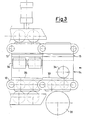
- Figure 3 is an enlarged raised side view of a detail of the two plants shown in Figure 1 and/or 2, taken next to the end of the straight portion, before the gap between the molding elements interfacing with each other;
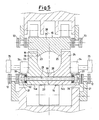
- Figure 4 is an enlarged transversal cross-section, taken along the line IV - IV of Figure 1 and/or 2;
- Figures 5 and 6 are enlarged transversal cross sections, taken along the line V - V of Figure 1 and/or 2, showing the chain and the relative molding elements in two different positions of forward motion;
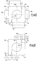
- Figures 7 and 8 are two simplified cross sections of a second embodiment of the molding elements, capable of being positioned on the opposing chains of the ingot mold of this invention;
- Figures 9 and 10 are two simplified cross sections of a third embodiment of the molding elements of the ingot mold of this invention, similar to that shown in Figures 7 and 8; and
- Figures 11 and 12 are two simplified cross sections of a fourth embodiment of the molding elements, capable of being positioned on the opposing chains of the ingot mold of this invention.
- The Figures 1 and 2 show two continuous casting plants, one of a vertical and the other of a horizontal type, both equipped with a sliding chain-type ingot mold according to this invention.
- The figures show a
basket 10 feeding a dragging chain-type ingot mold, indicated in its overall form by 11. - The
ingot mold 11 comprises two pairs ofchains type elements - The molding or shell-
type elements - The
ingot mold 11 is in fact designed so that the two pairs ofchains sprockets - In order to achieve this, a pair of
chains 13 carries somemolding elements 15 fitted in a terminal portion withexternal surfaces 19 capable of inserting and engaging themselves in correspondinginternal surfaces 18 of a terminal portion of the half-mold elements 14 carried by the other pair ofchains 12. This produces a length of continuous cavity, formed internally by thehalf molds tray 10 is directly cast. - The
molding elements base portion shaped walls - The pair of
chains 13 is arranged to the sides of thebase portion 21, just as the pair ofchains 12 is arranged to the sides of thebase portion 20. - In this second case it is also worth noting that the base portion carries two
lateral extensions 26, fitted with ahollow seat 27 housing a rod which also passes through ahole 29 in thebase portion 20. - This arrangement produces a connecting element designed to maintain a firm bond between the two
portions molding element 14 of the embodiment shown. It can in particular be noted that these twoportions complementary surfaces 30, around which the twoportions molding element 14 may oscillate in the way of a spherical coupling working in combination with an underlying barrel-shaped roller 39. - This oscillation is also possible because the two extremities of the
rod 28 are fitted, between thelocking nuts 31 and thehollow seats 27, with elastic elements such as cup-type springs or Bellevillesprings 32. - This arrangement guarantees contact but allows a slight reciprocal rotation. It is worth noting that the two
molding elements symmetry 38 perpendicular to the twobase portions - The upper surfaces of the two
lateral extensions 26 of thebase portion 20 are further equipped with two cam-shaped surfaces 33. These cam-shaped surfaces are capable of contacting and interacting with some engaging elements constituted by a pair ofrollers 34 in a fixedframe 35 at the extreme end of the straight portion of the ingot mold. The cam-shaped surfaces 33 are arranged along the longitudinal direction of motion of the two pairs of chains, and increase in height in the direction of their forward motion. - The straight portion of the ingot mold may provide for some
rollers 36, which are always firmly attached to thefixed frame 35. Theserollers 36, which are positioned from opposite sides on the external surfaces of the leg-shaped walls molding elements 14, form a lateral guide, thanks also to the presence ofsprings 37 capable of modulating their lateral pushing action. - Of course both sets of
multiple molding elements - The operation of an arrangement according to this invention is as follows.
- Some drive units, not shown, rotate the two pairs of
chains respective molding elements - When the liquid metal feed is started from the
tray 10, this metal enters between themolding elements chains - During the motion of the two pairs of
chains relative molding elements rollers 36 acting on the external surfaces of the leg-shaped walls molding elements 14. - This produces a composite and continuous forward motion nearly up to the end of the straight portion, where each of the engaged
molding elements - It is in this phase that the
cam surfaces 33 placed on theextensions 26 of thebase portion 20 of eachmolding element 14 come to interact with the engaging elements constituted by therollers 34. Since the cam-shaped surfaces 33 are rising in height in the direction of their forward motion, this generates, as shown in Figure 6, a reciprocal rotation between the twoportions molding element 14. The entire process is obviously made possible, as shown above, by the presence of the tworounded surfaces 30 and thesprings 32 placed on the extremities of therod 28 and the underlying barrel-shaped roller that acts to counter the rotation. - This slight rotation causes a detachment between the
internal surfaces 18 of themolding element 14 and theexternal surfaces 19 of themolding element 15 that facilitates their detachment. - This rotation also helps to prevent friction between the mentioned surfaces, and any undesirable deformations on the two molding elements.
- This solves the problems of the known continuous casting plants, while eliminating the wear which boosts the number of repairs and the operating costs of the ingot mold.
- Figures 7 and 8 show a simplified alternative first embodiment of molding elements capable of being positioned on the pairs of chains while using various means of engagement.
- In this embodiment the molding elements are generally produced, as shown before, one in a single piece and the other in two pieces. In this embodiment equal elements are designated by the same reference numbers as formerly used, preceded by the number "1".
- Each
lower molding element 114 is in fact produced in two portions, indicated by 114a and 114b, and presents an asymmetrical shape with respect to anaxis 138 set perpendicular to twobase portions - Figure 7 shows a first transversal cross section where it can be seen that in the
molding element 114 thebase portion 120 constitutes the first portion 114a, which is fitted on one side with a pointed leg-type wall 122. - The other side carries a
rounded surface 130 facing a complementaryrounded surface 130 of thesecond portion 114b. Thissecond portion 114b extends on the other side into a vertical leg-type wall 124, similar to theprevious walls 24, but arranged to the side of theupper base portion 121. - The
molding section 115 is simply constituted by a molding element rather similar to themolding element 114, but is rotated in its arrangement by 180° with respect to the mentionedaxis 138 of the mold, and produced from a single piece. - The internal surfaces of the leg-shaped
wall 124 of theupper molding element 115 are set against theexternal surfaces 118 of the pointed leg-shapedwall 122 of thelower molding element 114, and the same applies on the other side to the same leg-shapedwalls - It can be noted that the three pressurizing
rollers 136 form lateral guides and a fixedlower roller 140. - A second cross section in Figure 8 shows that there are two fixed upper and
lower rollers 139 acting to counter the motion. There are also two upper andlower pressurizing rollers 134 which act on the cam-shapedsurfaces 133 extending from the free extremities of theportion 114b of thelower molding element 114 and from the leg-shapedwall 124 of theupper molding element 115. The pressurizingrollers 134 act as external engaging elements. - This arrangement of the rollers promotes the detachment between the two
molding elements portion 114b around therounded surfaces 130 and the upper molding element with respect to the fixedupper roller 139. - An arrangement based on an
inclined rod 127 passing through somehollow seats 127 produces a connecting element designed to keep the twoportions 114a and 114b tied up to each other even during the oscillation. - Two further cross sections in Figures 9 and 10 offer a simplified view of an alternative embodiment very similar to the one shown in Figures 7 and 8.
- In this embodiment the
molding elements rounded surfaces 130. - In this manner both the
lower molding element 114 and theupper molding element 115 oscillate with respect to the two fixed lower andupper rollers 139, whenever the two upper andlower pressurizing rollers 134 act on the cam-type surface 133, if available, or by shifting the pressurizingrollers 134 with the aid of an appropriate actuator. - In a simplified manner, Figures 11 and 12 finally show a fourth alternative embodiment of some molding elements capable of being positioned on the pairs of chains.
- Even in this embodiment, both molding elements are produced from a single piece, and equal elements are indicated by the same reference numbers preceded by the number "2".
- A
lower molding element 214 is produced from a single piece and presents an asymmetrical shape with respect to anaxis 238 perpendicular to the twobase portions upper molding element 215 is simply constituted by a molding element entirely similar to thelower molding element 214, but rotated in its arrangement by 180° with respect to theaxis 238. - In the section shown in Figure 11 it can be seen that the
molding elements walls base portions - Even in this case there are three pressurizing
rollers 236 forming lateral guides, and a fixed lower supportingroller 240. - A second cross section in Figure 12 shows that there are two fixed
lateral rollers 239 acting to counter the motion, and two further pressurizingrollers 234 acting on the opposing lateral cam-shapedsurfaces 233 of the twomolding elements rollers 234 act as external engaging elements. - It is precisely this arrangement of rollers that promotes the detachment between the two
molding elements roller 239. - This produces the same technical solutions which are the object of this invention.
- It is obviously evident that there may be different arrangements of rollers and that the cam-shaped surfaces may be fixed to interact with the rollers, without abandoning the scope of protection of this invention.
- This accomplishes the purpose mentioned in the introductory description.
- The embodiments may naturally differ from those shown for purely exemplifying and non-limiting purposes in the drawings, just as there can be different elements of reciprocal engagement capable of generating the forcible separation of the molding elements while eliminating harmful friction.
- The scope of protection of the invention is in any case circumscribed by the enclosed claims.
Claims (11)
- An sliding chain-type ingot mold for a continuous casting plant, comprising two pairs of chains (12, 13) both arranged in a closed ring system and rotating in opposite directions, where each pair of chains (12, 13) carries a multiple number of molding or shell-type elements (14, 15; 114, 115; 214, 215) which represent two half molds capable of being made to interface with each other to form a closed mold and to produce a cavity to hold the molten metal, where said pairs of chains (12, 13) are arranged to wind up on sprockets (16, 17) while describing a straight portion between the same, and one pair of chains (13) carries molding elements (15, 115, 215) providing in their terminal portions certain surfaces (19, 119, 219) capable of engaging in the surfaces facing each other (18, 118, 218) of a terminal portion of some half-mold elements (14, 114, 214) carried by the other pair of chains (12) to form said cavity, characterized in that it provides for certain engaging elements (34, 134, 234) capable of interacting with cam-shaped surfaces (33, 133, 233) fitted on one side on at least one (14, 114, 214) of said molding elements and on the other side on a fixed frame (35) designed to detach and approach said surfaces (18, 19; 118, 119; 218, 219) engaging between each other at the end of said straight portion, and in that at least one (14, 114) of said molding elements (14, 15; 114, 115) is made up of two portions (14a, 14b; 114a, 114b) coupled in a slight rotatable engagement along opposing and rounded surfaces (30, 130), said surfaces being kept engaged to each other by coupling elements (28, 128).
- An ingot mold according to claim 1, characterized in that said coupling elements comprise a rool (28, 128) positioned in a base portion (20) of said molding element (14), said tool being further inserted in a hole (29, 129) provided in said two coupled portions (14a, 14b; 114a, 114b) and being kept in place by elastic elements (32).
- An ingot mold according to claim 2, characterized in that said engaging elements (34) capable of interacting with the said cam-shaped surfaces (33) are positioned opposite to and on some extensions (26) on 20 both sides of said base portion (20).
- An ingot mold according to claim 2, characterized in that a barrel-shaped roller (39) is arranged below said base portion (20) and opposite said interfacing rounded surfaces (30).
- An ingot mold according to claim 1, characterized in that said melding elements (14, 15) have a cross section basically shaped in a U-form and interpenetrate each other so as to position themselves opposite said interfacing surfaces (18, 19) of their terminal portions.
- An ingot mold according to claim 1 characterized in that said two portions (14a, 14b) of at least one of said molding elements (14) coupled along rounded interfacing surfaces (30) are essentially symmetrical with respect to an axis (38) set perpendicular to said base portion (20).
- An ingot mold according to claim 1, characterized in that said molding elements (114, 115; 214, 215) have essentially the same form, asymmetrical with respect to an axis (138, 238) perpendicular with respect to a base portion (120, 121; 220, 221), and are arranged so as to be rotated from each other by 180°, thus producing a cavity between them.
- An ingot mold according to claim 1, characterized in that said engaging elements (34, 134, 234) are rollers.
- An sliding chain-type ingot mold for a continuous casting plant comprising two pairs of chains (12, 13), both arranged in a closed ring system and rotating in opposite directions, where each pair of chains (12, 13) carries a multiple number of mold or shell-type elements (114, 115; 214, 215) representing two half molds capable of interfacing with each other so as to form a closed mold to produce a cavity to hold molten metal, where said two pairs of chains (12, 13) are arranged to wind up on sprockets (16, 17) so as to form a straight portion between them, and a pair. of chains (13) carry molding elements (115, 215) providing in one of their terminal portions some surfaces (119, 219) capable of engaging with interfacing surfaces (118, 218) of a terminal portion of half-mold elements (114, 214) carried by the other pair of chains (12) so as to form said cavity, characterized in that it provides for some external engaging elements (134, 234) capable of acting on the surfaces of said half-mold elements (114, 214; 115, 215) to detach or approach said surfaces (118, 119; 218, 219) engaging with each other at the end of said straight portion and being provided with some fixed contrasting elements (139, 239).
- An ingot mold according to claim 9, characterized in that said external engaging elements (134, 234) are pressurizing rollers.
- An ingot mold according to claim 9, characterized in that said fixed contrasting elements (139, 239) are rollers.
Applications Claiming Priority (2)
| Application Number | Priority Date | Filing Date | Title |
|---|---|---|---|
| IT97MI002416A IT1295884B1 (en) | 1997-10-28 | 1997-10-28 | PERFECTED CHAIN SLIDING INGOT MOLD FOR A CONTINUOUS CASTING PLANT |
| ITMI972416 | 1997-10-28 |
Publications (2)
| Publication Number | Publication Date |
|---|---|
| EP0913216A1 EP0913216A1 (en) | 1999-05-06 |
| EP0913216B1 true EP0913216B1 (en) | 2002-09-11 |
Family
ID=11378115
Family Applications (1)
| Application Number | Title | Priority Date | Filing Date |
|---|---|---|---|
| EP98203568A Expired - Lifetime EP0913216B1 (en) | 1997-10-28 | 1998-10-22 | Improved sliding chain-type ingot mold for a continuous casting plant |
Country Status (9)
| Country | Link |
|---|---|
| US (2) | US6192972B1 (en) |
| EP (1) | EP0913216B1 (en) |
| JP (1) | JP4262337B2 (en) |
| CN (1) | CN1114512C (en) |
| AT (1) | ATE223771T1 (en) |
| CA (1) | CA2251524C (en) |
| DE (1) | DE69807815T2 (en) |
| ES (1) | ES2181122T3 (en) |
| IT (1) | IT1295884B1 (en) |
Families Citing this family (7)
| Publication number | Priority date | Publication date | Assignee | Title |
|---|---|---|---|---|
| DE10051489A1 (en) | 2000-10-17 | 2002-04-18 | Sms Demag Ag | Plate mold used in the continuous casting of steel has mold plate pairs joined together at the corner joints and held together by water tanks which are connected by tensioning elements |
| CN102151810B (en) * | 2011-03-25 | 2013-06-12 | 中国重型机械研究院有限公司 | Design method of anti-slip device |
| ITMI20120979A1 (en) * | 2012-06-06 | 2013-12-07 | Danieli Off Mecc | TEMPLATE FOR THE CENTERING OF ROLLERS TO THE FOOT OF A FEELER |
| CN103752786A (en) * | 2014-02-17 | 2014-04-30 | 张瑞华 | Crawler type storage battery grid continuous casting machine |
| IT201800006009A1 (en) * | 2018-06-04 | 2019-12-04 | CONTINUOUS CASTING SYSTEM OF PRODUCTS | |
| CN110328348B (en) * | 2019-06-27 | 2021-12-31 | 广东银迪压铸有限公司 | Production method of new energy automobile motor aluminum shell |
| US11787133B2 (en) | 2022-01-25 | 2023-10-17 | The Boeing Company | Conveyor forming composite stringers |
Family Cites Families (5)
| Publication number | Priority date | Publication date | Assignee | Title |
|---|---|---|---|---|
| US1841297A (en) * | 1928-04-26 | 1932-01-12 | John E Perry | Apparatus and method of continuous casting of steel |
| US1865443A (en) * | 1928-11-06 | 1932-07-05 | John E Perry | Method and apparatus for continuous casting of steel billets |
| JPH01306053A (en) * | 1988-06-01 | 1989-12-11 | Ishikawajima Harima Heavy Ind Co Ltd | Track type continuous casting machine |
| US5645159A (en) * | 1994-03-30 | 1997-07-08 | Lauener Engineering, Ltd. | Method and apparatus for continuously casting metal |
| AT405254B (en) * | 1996-02-20 | 1999-06-25 | Hulek Anton | TRACKED CHILLER FOR A CONTINUOUS CASTING SYSTEM |
-
1997
- 1997-10-28 IT IT97MI002416A patent/IT1295884B1/en active IP Right Grant
-
1998
- 1998-10-22 AT AT98203568T patent/ATE223771T1/en active
- 1998-10-22 DE DE69807815T patent/DE69807815T2/en not_active Expired - Lifetime
- 1998-10-22 EP EP98203568A patent/EP0913216B1/en not_active Expired - Lifetime
- 1998-10-22 ES ES98203568T patent/ES2181122T3/en not_active Expired - Lifetime
- 1998-10-26 US US09/178,429 patent/US6192972B1/en not_active Expired - Lifetime
- 1998-10-27 CA CA002251524A patent/CA2251524C/en not_active Expired - Fee Related
- 1998-10-28 JP JP30733098A patent/JP4262337B2/en not_active Expired - Fee Related
- 1998-10-28 CN CN98123475A patent/CN1114512C/en not_active Expired - Fee Related
-
2000
- 2000-12-21 US US09/741,341 patent/US6338379B2/en not_active Expired - Lifetime
Also Published As
| Publication number | Publication date |
|---|---|
| CA2251524A1 (en) | 1999-04-28 |
| US6338379B2 (en) | 2002-01-15 |
| ITMI972416A1 (en) | 1999-04-28 |
| DE69807815T2 (en) | 2003-08-07 |
| DE69807815D1 (en) | 2002-10-17 |
| JP4262337B2 (en) | 2009-05-13 |
| ATE223771T1 (en) | 2002-09-15 |
| CN1114512C (en) | 2003-07-16 |
| EP0913216A1 (en) | 1999-05-06 |
| CA2251524C (en) | 2006-09-05 |
| US20010000589A1 (en) | 2001-05-03 |
| ES2181122T3 (en) | 2003-02-16 |
| JPH11221653A (en) | 1999-08-17 |
| US6192972B1 (en) | 2001-02-27 |
| IT1295884B1 (en) | 1999-05-28 |
| CN1219449A (en) | 1999-06-16 |
Similar Documents
| Publication | Publication Date | Title |
|---|---|---|
| CA2251524C (en) | Improved sliding chain-type ingot mold for a continuous casting plant | |
| US4854371A (en) | Twin belt type continuous casting machine | |
| AU1453295A (en) | Continuous casting ingot mould for guiding continuous castings | |
| US3415306A (en) | Method of continuous casting without applying tension to the strand | |
| EP0539861B1 (en) | Crystallizer, or inner portion, of a mould having a lengthwise curvature for continuous curved casting of thin slabs | |
| US4895202A (en) | Endless track type continuous casting machine | |
| EP0317283A1 (en) | Endless track type continuous casting machine | |
| US3435879A (en) | Continuous casting method | |
| EP0317285B1 (en) | Endless track type continuous casting machine | |
| US20090183851A1 (en) | Process for the continuous casting of flat metal products with electromagnetic stirring and implementation installation | |
| JPS6037248A (en) | Continuous casting machine | |
| CZ288903B6 (en) | Crawler-mounted ingot mold for a continuous casting plant | |
| HK1020325A (en) | Improved sliding chain-type ingot mold for a continuous casting plant | |
| EP0933152B1 (en) | A variable section mobile ingot mold for a continuous casting plant | |
| JPH0349657B2 (en) | ||
| KR20140002097A (en) | Continuous casting machine having segment | |
| CN211360594U (en) | Billet guiding and conveying device of continuous casting machine | |
| JPS63149047A (en) | Block mold conveyance device for endless track casting machine | |
| SU1614895A1 (en) | Machine for continuous casting of hollow blanks of vertical type | |
| JPH01278943A (en) | Traveling head for horizontal continuous casting device | |
| JP2801042B2 (en) | Continuous casting equipment | |
| JPH01130855A (en) | Track type continuous casting machine | |
| SU1215850A1 (en) | Machine for continuous casting of shapes | |
| JPS63149052A (en) | Shifting mold type continuous casting machine | |
| JPH01130853A (en) | Caterpillar type continuous casting machine |
Legal Events
| Date | Code | Title | Description |
|---|---|---|---|
| PUAI | Public reference made under article 153(3) epc to a published international application that has entered the european phase |
Free format text: ORIGINAL CODE: 0009012 |
|
| AK | Designated contracting states |
Kind code of ref document: A1 Designated state(s): AT BE CH CY DE DK ES FI FR GB GR LI |
|
| AX | Request for extension of the european patent |
Free format text: AL;LT;LV;MK;RO;SI |
|
| 17P | Request for examination filed |
Effective date: 19990910 |
|
| AKX | Designation fees paid |
Free format text: AT BE CH CY DE DK ES FI FR GB GR LI |
|
| RBV | Designated contracting states (corrected) |
Designated state(s): AT BE CH DE ES FR GB GR LI LU PT SE |
|
| 17Q | First examination report despatched |
Effective date: 20010115 |
|
| GRAG | Despatch of communication of intention to grant |
Free format text: ORIGINAL CODE: EPIDOS AGRA |
|
| GRAG | Despatch of communication of intention to grant |
Free format text: ORIGINAL CODE: EPIDOS AGRA |
|
| GRAH | Despatch of communication of intention to grant a patent |
Free format text: ORIGINAL CODE: EPIDOS IGRA |
|
| GRAH | Despatch of communication of intention to grant a patent |
Free format text: ORIGINAL CODE: EPIDOS IGRA |
|
| RAP1 | Party data changed (applicant data changed or rights of an application transferred) |
Owner name: VAI POMINI S.R.L. |
|
| GRAA | (expected) grant |
Free format text: ORIGINAL CODE: 0009210 |
|
| AK | Designated contracting states |
Kind code of ref document: B1 Designated state(s): AT BE CH DE ES FR GB GR LI LU PT SE |
|
| PG25 | Lapsed in a contracting state [announced via postgrant information from national office to epo] |
Ref country code: GR Free format text: LAPSE BECAUSE OF FAILURE TO SUBMIT A TRANSLATION OF THE DESCRIPTION OR TO PAY THE FEE WITHIN THE PRESCRIBED TIME-LIMIT Effective date: 20020911 Ref country code: FR Free format text: LAPSE BECAUSE OF FAILURE TO SUBMIT A TRANSLATION OF THE DESCRIPTION OR TO PAY THE FEE WITHIN THE PRESCRIBED TIME-LIMIT Effective date: 20020911 Ref country code: BE Free format text: LAPSE BECAUSE OF FAILURE TO SUBMIT A TRANSLATION OF THE DESCRIPTION OR TO PAY THE FEE WITHIN THE PRESCRIBED TIME-LIMIT Effective date: 20020911 |
|
| REF | Corresponds to: |
Ref document number: 223771 Country of ref document: AT Date of ref document: 20020915 Kind code of ref document: T |
|
| REG | Reference to a national code |
Ref country code: GB Ref legal event code: FG4D |
|
| REG | Reference to a national code |
Ref country code: CH Ref legal event code: EP |
|
| REF | Corresponds to: |
Ref document number: 69807815 Country of ref document: DE Date of ref document: 20021017 |
|
| PG25 | Lapsed in a contracting state [announced via postgrant information from national office to epo] |
Ref country code: LU Free format text: LAPSE BECAUSE OF NON-PAYMENT OF DUE FEES Effective date: 20021022 |
|
| PG25 | Lapsed in a contracting state [announced via postgrant information from national office to epo] |
Ref country code: SE Free format text: LAPSE BECAUSE OF FAILURE TO SUBMIT A TRANSLATION OF THE DESCRIPTION OR TO PAY THE FEE WITHIN THE PRESCRIBED TIME-LIMIT Effective date: 20021211 Ref country code: GB Free format text: LAPSE BECAUSE OF NON-PAYMENT OF DUE FEES Effective date: 20021211 |
|
| PG25 | Lapsed in a contracting state [announced via postgrant information from national office to epo] |
Ref country code: PT Free format text: LAPSE BECAUSE OF FAILURE TO SUBMIT A TRANSLATION OF THE DESCRIPTION OR TO PAY THE FEE WITHIN THE PRESCRIBED TIME-LIMIT Effective date: 20021217 |
|
| REG | Reference to a national code |
Ref country code: CH Ref legal event code: NV Representative=s name: AMMANN PATENTANWAELTE AG BERN |
|
| REG | Reference to a national code |
Ref country code: ES Ref legal event code: FG2A Ref document number: 2181122 Country of ref document: ES Kind code of ref document: T3 |
|
| EN | Fr: translation not filed | ||
| PLBE | No opposition filed within time limit |
Free format text: ORIGINAL CODE: 0009261 |
|
| STAA | Information on the status of an ep patent application or granted ep patent |
Free format text: STATUS: NO OPPOSITION FILED WITHIN TIME LIMIT |
|
| GBPC | Gb: european patent ceased through non-payment of renewal fee | ||
| 26N | No opposition filed |
Effective date: 20030612 |
|
| REG | Reference to a national code |
Ref country code: CH Ref legal event code: PFA Owner name: SIEMENS VAI METALS TECHNOLOGIES S.R.L. Free format text: VAI POMINI S.R.L.#VIA LEONARDO DA VINCI 20#21053 CASTELLANZA-VARESE (IT) -TRANSFER TO- SIEMENS VAI METALS TECHNOLOGIES S.R.L.#VIA LUIGI POMINI 92#21050 MARNATE (VA) (IT) Ref country code: CH Ref legal event code: NV Representative=s name: SIEMENS SCHWEIZ AG |
|
| REG | Reference to a national code |
Ref country code: CH Ref legal event code: PFA Owner name: SIEMENS S.P.A., IT Free format text: FORMER OWNER: SIEMENS VAI METALS TECHNOLOGIES S.R.L., IT |
|
| REG | Reference to a national code |
Ref country code: DE Ref legal event code: R082 Ref document number: 69807815 Country of ref document: DE Representative=s name: KINNSTAETTER, KLAUS, DIPL.-PHYS.UNIV., DE Ref country code: DE Ref legal event code: R082 Ref document number: 69807815 Country of ref document: DE |
|
| REG | Reference to a national code |
Ref country code: ES Ref legal event code: PC2A Owner name: SIEMENS S.P.A. Effective date: 20131202 |
|
| REG | Reference to a national code |
Ref country code: DE Ref legal event code: R081 Ref document number: 69807815 Country of ref document: DE Owner name: PRIMETALS TECHNOLOGIES ITALY S.R.L., IT Free format text: FORMER OWNER: VAI POMINI S.R.L., CASTELLANZA, VARESE, IT Effective date: 20131128 Ref country code: DE Ref legal event code: R081 Ref document number: 69807815 Country of ref document: DE Owner name: SIEMENS S.P.A., IT Free format text: FORMER OWNER: VAI POMINI S.R.L., CASTELLANZA, VARESE, IT Effective date: 20131128 Ref country code: DE Ref legal event code: R081 Ref document number: 69807815 Country of ref document: DE Owner name: SIEMENS S.P.A., IT Free format text: FORMER OWNER: VAI POMINI S.R.L., CASTELLANZA, IT Effective date: 20131128 |
|
| REG | Reference to a national code |
Ref country code: AT Ref legal event code: PC Ref document number: 223771 Country of ref document: AT Kind code of ref document: T Owner name: SIEMENS S.P.A., IT Effective date: 20140128 |
|
| REG | Reference to a national code |
Ref country code: DE Ref legal event code: R081 Ref document number: 69807815 Country of ref document: DE Owner name: PRIMETALS TECHNOLOGIES ITALY S.R.L., IT Free format text: FORMER OWNER: SIEMENS S.P.A., MAILAND/MILANO, IT |
|
| REG | Reference to a national code |
Ref country code: CH Ref legal event code: PFA Owner name: PRIMETALS TECHNOLOGIES ITALY S.R.L., IT Free format text: FORMER OWNER: SIEMENS S.P.A., IT |
|
| REG | Reference to a national code |
Ref country code: ES Ref legal event code: PC2A Owner name: PRIMETALS TECHNOLOGIES ITALY S.R.L. Effective date: 20160505 |
|
| PGFP | Annual fee paid to national office [announced via postgrant information from national office to epo] |
Ref country code: CH Payment date: 20161020 Year of fee payment: 19 Ref country code: DE Payment date: 20161020 Year of fee payment: 19 |
|
| PGFP | Annual fee paid to national office [announced via postgrant information from national office to epo] |
Ref country code: AT Payment date: 20161020 Year of fee payment: 19 Ref country code: ES Payment date: 20161011 Year of fee payment: 19 |
|
| REG | Reference to a national code |
Ref country code: DE Ref legal event code: R119 Ref document number: 69807815 Country of ref document: DE |
|
| REG | Reference to a national code |
Ref country code: CH Ref legal event code: PL |
|
| REG | Reference to a national code |
Ref country code: AT Ref legal event code: MM01 Ref document number: 223771 Country of ref document: AT Kind code of ref document: T Effective date: 20171022 |
|
| PG25 | Lapsed in a contracting state [announced via postgrant information from national office to epo] |
Ref country code: CH Free format text: LAPSE BECAUSE OF NON-PAYMENT OF DUE FEES Effective date: 20171031 Ref country code: LI Free format text: LAPSE BECAUSE OF NON-PAYMENT OF DUE FEES Effective date: 20171031 Ref country code: DE Free format text: LAPSE BECAUSE OF NON-PAYMENT OF DUE FEES Effective date: 20180501 |
|
| PG25 | Lapsed in a contracting state [announced via postgrant information from national office to epo] |
Ref country code: AT Free format text: LAPSE BECAUSE OF NON-PAYMENT OF DUE FEES Effective date: 20171022 |
|
| REG | Reference to a national code |
Ref country code: ES Ref legal event code: FD2A Effective date: 20181221 |
|
| PG25 | Lapsed in a contracting state [announced via postgrant information from national office to epo] |
Ref country code: ES Free format text: LAPSE BECAUSE OF NON-PAYMENT OF DUE FEES Effective date: 20171023 |