EP0913027B1 - Method for commutating a brushless motor and power supply for a brushless motor - Google Patents
Method for commutating a brushless motor and power supply for a brushless motor Download PDFInfo
- Publication number
- EP0913027B1 EP0913027B1 EP97930363A EP97930363A EP0913027B1 EP 0913027 B1 EP0913027 B1 EP 0913027B1 EP 97930363 A EP97930363 A EP 97930363A EP 97930363 A EP97930363 A EP 97930363A EP 0913027 B1 EP0913027 B1 EP 0913027B1
- Authority
- EP
- European Patent Office
- Prior art keywords
- current
- motor
- intermediary circuit
- commutation
- value
- Prior art date
- Legal status (The legal status is an assumption and is not a legal conclusion. Google has not performed a legal analysis and makes no representation as to the accuracy of the status listed.)
- Expired - Lifetime
Links
- 238000000034 method Methods 0.000 title claims description 15
- 238000012937 correction Methods 0.000 claims abstract description 10
- 230000003111 delayed effect Effects 0.000 claims abstract description 7
- 238000005259 measurement Methods 0.000 claims description 8
- 230000001419 dependent effect Effects 0.000 claims description 6
- 238000001914 filtration Methods 0.000 claims description 6
- 238000005070 sampling Methods 0.000 claims description 6
- 238000004804 winding Methods 0.000 description 7
- 230000007423 decrease Effects 0.000 description 4
- 238000010586 diagram Methods 0.000 description 3
- 230000015572 biosynthetic process Effects 0.000 description 2
- 239000003990 capacitor Substances 0.000 description 2
- 238000012545 processing Methods 0.000 description 2
- 230000002035 prolonged effect Effects 0.000 description 2
- 238000005057 refrigeration Methods 0.000 description 2
- 230000006641 stabilisation Effects 0.000 description 2
- 238000012360 testing method Methods 0.000 description 2
- 102000016550 Complement Factor H Human genes 0.000 description 1
- 108010053085 Complement Factor H Proteins 0.000 description 1
- 238000004378 air conditioning Methods 0.000 description 1
- 238000004364 calculation method Methods 0.000 description 1
- 230000006835 compression Effects 0.000 description 1
- 238000007906 compression Methods 0.000 description 1
- 230000001276 controlling effect Effects 0.000 description 1
- 238000001816 cooling Methods 0.000 description 1
- 230000003247 decreasing effect Effects 0.000 description 1
- 238000013461 design Methods 0.000 description 1
- 238000011161 development Methods 0.000 description 1
- 238000007599 discharging Methods 0.000 description 1
- 230000004907 flux Effects 0.000 description 1
- 102000051759 human factor J Human genes 0.000 description 1
- 108700008420 human factor J Proteins 0.000 description 1
- 230000001788 irregular Effects 0.000 description 1
- 238000004519 manufacturing process Methods 0.000 description 1
- 238000012544 monitoring process Methods 0.000 description 1
- 230000010355 oscillation Effects 0.000 description 1
- 230000002265 prevention Effects 0.000 description 1
- 239000003507 refrigerant Substances 0.000 description 1
- 230000001105 regulatory effect Effects 0.000 description 1
- 230000001360 synchronised effect Effects 0.000 description 1
- 230000003245 working effect Effects 0.000 description 1
Images

Classifications
-
- H—ELECTRICITY
- H02—GENERATION; CONVERSION OR DISTRIBUTION OF ELECTRIC POWER
- H02P—CONTROL OR REGULATION OF ELECTRIC MOTORS, ELECTRIC GENERATORS OR DYNAMO-ELECTRIC CONVERTERS; CONTROLLING TRANSFORMERS, REACTORS OR CHOKE COILS
- H02P6/00—Arrangements for controlling synchronous motors or other dynamo-electric motors using electronic commutation dependent on the rotor position; Electronic commutators therefor
- H02P6/14—Electronic commutators
-
- H—ELECTRICITY
- H02—GENERATION; CONVERSION OR DISTRIBUTION OF ELECTRIC POWER
- H02P—CONTROL OR REGULATION OF ELECTRIC MOTORS, ELECTRIC GENERATORS OR DYNAMO-ELECTRIC CONVERTERS; CONTROLLING TRANSFORMERS, REACTORS OR CHOKE COILS
- H02P29/00—Arrangements for regulating or controlling electric motors, appropriate for both AC and DC motors
- H02P29/40—Regulating or controlling the amount of current drawn or delivered by the motor for controlling the mechanical load
-
- H—ELECTRICITY
- H02—GENERATION; CONVERSION OR DISTRIBUTION OF ELECTRIC POWER
- H02P—CONTROL OR REGULATION OF ELECTRIC MOTORS, ELECTRIC GENERATORS OR DYNAMO-ELECTRIC CONVERTERS; CONTROLLING TRANSFORMERS, REACTORS OR CHOKE COILS
- H02P2201/00—Indexing scheme relating to controlling arrangements characterised by the converter used
- H02P2201/07—DC-DC step-up or step-down converter inserted between the power supply and the inverter supplying the motor, e.g. to control voltage source fluctuations, to vary the motor speed
Definitions
- the invention concerns a method for commutating a brushless motor, supplied with electrical energy from a DC intermediary circuit via a multi-phase inverter, by which a first current value and a second current value are determined, and the duration of a commutation interval is set in dependence of these current values. Further, the invention concerns a power supply for a brushless motor, the motor being connected with a DC intermediary circuit via an inverter, comprising a control unit with an input connected to the DC intermediary circuit.
- the motor can also be controlled by means of this information.
- This principle can be used for both AC and three-phase current synchronous motors, and for brushless DC motors as well.
- commutation time dynamically as a function of the current in the intermediary circuit.
- the current is measured and converted to a processable parameter.
- This parameter is compared with a predetermined reference parameter.
- the commutation interval is either kept constant or reduced or prolonged.
- commutation interval means the time between the individual commutations.
- US 5,420,492 describes a design, in which the commutation frequency, i.e. the frequency of commutations, is changed in dependence of the current over time, i.e. in dependence of the current waveshape profile.
- This current waveshape profile is compared with a pre-set profile. The contour of the current profile depends on whether the commutation time was correct, too early or too late.
- the slope of the current is determined. When the moment of commutation occurs too early, i.e. is ahead of the rotor, the slope will be too flat. When the commutation occurs too late, the slope will be too steep.
- the commutation interval is either reduced or prolonged, and a new test is made, until the correct profile, and thus the correct commutation interval, has been set. This is done via a change of the commutation frequency.
- the optimum profile of the current i.e. the optimum slope or the optimum relation between the two current values.
- the values can be determined empirically for the unloaded motor and then be taken from a look-up table during the operation. For a loaded motor, however, this determination is relatively difficult, as the kind and size of the load is not known. In dynamic systems with heavily varying loads, a correspondingly large number of reference parameters would be necessary.
- Piston compressors are for example used in refrigeration systems, in which they drive a refrigerant gas through a capacitor and an evaporator.
- the load torque is varying over a cycle, i.e. over a piston stroke.
- a typical load curve starts in the lower dead point with a small torque of approximately 0 Nm. The closer the piston comes to the upper dead point, the faster the torque increases. In most cases this increase is not linear.
- the outlet valve of the compressor opens in the range of the upper dead point, or somewhat earlier, e.g. at 150°.
- the load torque then decreases very rapidly and steeply. Normally this load-torque-decrease is not linear either.
- the task of the invention is to create a stable operation of motors with unequal loads.
- this task is solved in that a correction value is added to a given commutation interval determined by the speed of the motor, said correction value resulting from the difference between the actual value of the intermediary circuit current and a filtered, time delayed value of the intermediary circuit current, the difference being multiplied by a weighting factor, and that the actual value of the intermediary circuit current is determined at a predetermined time during the commutation interval.
- the information contained in both current values are immediately used to change the commutation interval, as the load of the motor is immediately expressed in a change of the intermediary circuit current.
- the intermediary circuit current increases correspondingly.
- the commutation interval must be changed simultaneously. It has been found that the required change of the commutation interval is approximately proportional to the difference between the two current values, provided that the current values are not used immediately, but only after a filtering of at least the delayed, i.e. the previous, current value.
- filtering can also be understood as the formation of a mean value.
- the monitoring is not limited to a current waveshape profile. On the contrary, the overall current increase and decrease occurring on load changes of the motor are evaluated to determine the commutation interval.
- the commutation interval is determined on the basis of the speed of the motor, which can be pre-set, the result of the proposed method is that the changes will always be close to this pre-set reference value. Thus there will be no "wild" changes of the commutation intervals. On the contrary, the commutation interval corresponding to the speed will only be slightly increased or decreased, as required by the load. Thus the sampling is load dependent.
- the weighting factor is chosen in dependence of the speed.
- the weighting factor is reversely proportional to the speed, i.e. the higher the speed, the lower the weighting factor.
- the speed is the desired speed or reference speed.
- the actual or instantaneous value of the intermediary circuit current is determined at least once per commutation interval and no earlier than in the middle of this commutation interval.
- the actual value of the intermediary circuit current is not submitted to filtering. Thus, it also changes rather markedly within a commutation interval. At the beginning of a commutation interval the current is small and then it increases. Awaiting the end of this increase, which will with sufficient certainty be finished in the middle of a commutation interval, a statement of the "real" current value in this commutation interval is obtained.
- the inverter is block commutated.
- the block commutation means that the inverter is operated with a constant duty ratio. This means that the current in the intermediary circuit corresponds approximately to the current through the individual phases, i.e. the individual phases are not modulated in the meantime.
- PWM pulse width modulation
- a brushless DC motor is used as motor.
- Such a motor has for instance a rotor with magnets on the surface, which produce a trapezoidal counter-electromotive force.
- the motor is a switched reluctance motor.
- This motor can be controlled in the same way as a brushless DC motor, as the current in the intermediary circuit is an expression of the shaft load. The currents measured in the intermediary circuit can then be used as reference values for the commutation times.
- the reluctance motor turns out to be robust, especially with regard to temperature influences.
- control unit comprises a filter device filtering, delaying and inverting the intermediary circuit current, a summation point forming the difference between the filtered and delayed intermediary circuit current and the actual intermediary circuit current, a multiplier multiplying the difference by a weighting factor and another summation point in which the product of this multiplication is added as correction value to a speed dependent commutation interval, by which the output of the last summation point is connected with the inverter.
- This power supply provides an easy way of subtracting the mean or filtered and time-delayed intermediary circuit current from the actual intermediary circuit current, and multiplying the resulting difference by a weighting factor.
- the inversion of the current creates the negative value of the current, so that the difference is obtained at the summation point.
- the parameter occurring in this way can be used to change the commutation interval. Therefore, this size can also be lead immediately to the inverter, without requiring further cumbersome workings or calculations.
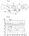
- Fig. 1 shows a power supply 1 for a motor-compressor unit 2, comprising a brushless DC motor 3 and a compressor 4.
- the compressor is part of a not shown refrigeration system needed for the operation of an air-conditioning system in a vehicle.
- the power supply 1 comprises a voltage source 5, e.g. a car battery, which is connected with a DC intermediary circuit 7 via a DC/DC voltage converter 6.
- the DC intermediary circuit 7 is connected with an inverter 8.
- the DC/DC converter 6 is controllable. If the voltage source 5 is an AC voltage source, the DC/DC converter 6 can be replaced by a controlled rectifier.
- the DC voltage supplied to the intermediary circuit 7 by the DC/DC converter 6 is collected via a pick-off or sensor 9 and supplied to an input U DC of a control unit 10.
- the DC current through the intermediary circuit is determined via a resistor 11 and also supplied to the control unit 10 via an input I DC .
- a capacitor 12 can also be arranged parallel to the output of the DC/DC converter 6.
- control unit 10 controls DC/DC converter 6 so that the power in the DC intermediary circuit 7, i.e. the product of intermediary circuit current I DC and intermediary circuit voltage U DC is minimised.
- the control unit 10 produces the control impulses for the switches in the inverter 8.
- the inverter 8 can be block commutated, and as usual consisting of six switches and six diodes.
- the switches in the inverter are active in pairs, so that the current from the intermediary circuit flows in through a first switch, then through a first motor winding of a first phase, on through a second motor winding of a second phase and out through a second switch.
- Each switch is closed for 120° and open for 240° (electrical degrees).
- a complete block commutation of the inverter 8 takes place without any modulation at all, i.e. the inverter 8 emits voltage blocks, whose amplitude corresponds to the intermediary circuit voltage U DC .
- the motor 3 drives a compressor 4, it has a period with a very unstable load behaviour, which appears from fig. 2.
- the piston of the compressor 4 starts in the lower dead point (0°) and moves towards the upper dead point (180°), and during this movement the load torque increases quickly and unlinearily. The increase continues until the pressure valve opens, which normally happens somewhat before the upper dead point is reached, e.g. at 150°. Then the load torque decreases to the value zero again during the down-movement of the piston.
- the motor speed falls during the load rise, which can be seen from fig. 4, which shows the motor speed with the same time scale as the one stated in fig. 2.
- the rotor changes its rotational speed during a rotation. Sometimes it rotates slower, sometimes faster, than the actually pre-set speed of 2,000 r.p.m.
- the inverter normally produces a rotary field rotating at constant angle speed, which rotary field, due to the load pattern described above, would run either ahead of or behind the rotor. This involves the risk that the rotor can no longer rotate synchronously with the rotary field causing the rotor to stop or jump. Both things are undesirable.
- control unit 10 controls the inverter 8 so that the commutation intervals change within one rotation.
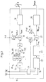
- the control unit 10 is shown in detail in fig. 3. It has two branches 19, 20.
- the branch 20 is used for the control of the commutation times of the inverter 8.
- the instantaneous or actual current I DC measured in the resistor 11 is led through the branch 20, which comprises a digital filter 13.
- the branch 20 ends at a signal generator 18 supplying the commutation signals for the switches in the inverter 8.
- the digital filter 13 consists of the factors H, J and K.
- the values in this embodiment example are 0.1, 0.9 and 0.38 (ms/A), respectively.
- the measured current I DC is multiplied by the factor H (0.1) and in a summation point 14 added to a value I DC,filt .
- This value I DC,filt is delayed in a delay link 21 and weighted with the factor J (0.9).
- the correction contribution K x (I DC - I DC,filt ) is added to a commutation interval reference value t kom0, which has been converted from the speed reference value n ref into a commutation interval in a converter 16.
- the sum, t kom formed in the summation point 17 represents the final commutation time, which is the basis of the control of the inverter 8.
- the commutation interval t kom0 can be calculated directly on the basis of the speed.
- a required speed of e.g. 2000 r.p.m. and a four-pole motor results in a fundamental frequency of 66.7 Hz. With twelve commutations per rotation this gives a commutation time t kom0 of 2.5 ms per commutation.
- Fig. 5 shows how the lengths of the commutation intervals change at a rotation of the rotor.
- Fig. 5 has the same time scale as the figs. 2 and 4. It is clearly seen that the commutation interval at the highest load, i.e. when the piston is at 150°, also has the longest extension, whereas the commutation interval is shortest when the motor is not loaded.
- the factor K is speed dependent. In this case it has the value of 0.38 ms/A at a speed of 2,000 r.p.m. At 4,000 r.p.m. it would be 0.19 ms/A. Thus the dynamic of the stabilisation is secured at all speeds.
- the current I DC,filt has been filtered through a digital filter.
- a continuos arithmetic mean value formation of the current as filtering.
- the measurement of the current in the intermediary circuit takes place in the second half of a commutation period, i.e. not earlier than in the middle of a commutation period and not later than shortly before it ends. Tests have shown that this gives the most reliable result.
- fig. 6 shows the intermediary circuit current I DC with loaded motor.
- Curve b shows the current in one of the motor windings.
- the current I DC in the intermediary circuit does not reach its maximum until some time after the commutation. The time required by the current to reach its maximum among other things depends on when the commutation takes place, i.e. if it takes place early or late.
- the increase in the current is much slower. Therefore, it is important not to sample until the current has at least approximately reached its maximum value.
- the current I DC should not be measured until the middle of a commutation period t p has been reached, which, in this embodiment example, means about 1.25 ms after a commutation.
- t p the sampling instant is shown by means of points in two periods.
- one of the phase currents to the motor is equal to the intermediary circuit current I DC , when disregarding short discharging phenomena at turning off the current to a phase winding.
- the shape of the current pulses among others depends on the type of rotor used. In this example the rotor has surface-mounted permanent magnets producing a trapezoidal counter-electromotive force.
- the method of commutation of a brushless DC motor described here bears the advantage that the control of the motor remains stable in spite of a very irregular type of load torque.
- the motor does not stop or jump.
- the control permits an operation with improved operational reliability.
- it is relatively inexpensive, as current measurements must only be made in the intermediary circuit. Information about rotor speed and position is not required.
- the power minimising algorithm is carried through.
- the measured intermediary circuit current I DC is filtered in an analogue filter 24, and is led to a processing unit 22 together with the intermediary circuit voltage U DC , in which processing unit the power consumption in the intermediary circuit is calculated on the basis of the product I DC x U DC .
- processing unit the power consumption in the intermediary circuit is calculated on the basis of the product I DC x U DC .
- the intermediary circuit voltage U DC is varying.
- the actual power consumption is compared with a previously measured power consumption, and the output signal is a voltage U reg , which can be either positive or negative.
- U reg is the sum of the previous U reg and a control contribution dU reg , which is in this case set fixedly at 0.25 V.
- dU reg a voltage change is carried through stepwise, and for so long that a power minimum has been reached.
- the voltage U reg is led to a summation point 27, which also receives a load dependent voltage contribution formed in a unit 25.
- This load dependent contribution is determined by means of the product of twice R f x I DCF , the F in the index of the current meaning that this current has already passed the analogue filter 24. This contribution helps to speed up the control and normally amounts to 10 to 20% of the output value of the summation point 27. In less time critical applications this contribution can be omitted.
- a speed reference value is led to the summation point 27, which value is created in a unit 26 by the speed reference value n ref .
- the voltage determined on the basis of this can be calculated by means of a motor constant K e .
- the voltage determined in the unit 26 corresponds to the electromotive counter-voltage of the motor 3.
- the voltage contribution U reg led to the summation point 27 can either increase or reduce the voltage U DC,ref . If the actual power consumption is lower than the previously measured power consumption after a reduction of the intermediary circuit voltage, the sign of the control contribution dU reg is maintained, i.e. the intermediary circuit voltage is reduced by another step, and this loop is passed until an increase in the power consumption occurs. Then the control contribution dU reg will change its sign.
- the DC regulating unit 6 can be a boost converter with one single switch, said converter being pulse width modulated.
- the switch losses are considerably reduced. Further, this will reduce the heat development and thus the need for cooling.
Landscapes
- Engineering & Computer Science (AREA)
- Power Engineering (AREA)
- Control Of Motors That Do Not Use Commutators (AREA)
Abstract
Description
- The invention concerns a method for commutating a brushless motor, supplied with electrical energy from a DC intermediary circuit via a multi-phase inverter, by which a first current value and a second current value are determined, and the duration of a commutation interval is set in dependence of these current values. Further, the invention concerns a power supply for a brushless motor, the motor being connected with a DC intermediary circuit via an inverter, comprising a control unit with an input connected to the DC intermediary circuit.
- With inverter controlled motors the individual motor phases must be turned on with optimum timing. Turn on must take place in correspondence with the counter voltage or counter-electromotive force (back-EMF) produced by the rotor, so that the motor does not get out of phase or timing, i.e. jumps, or even stops. This is especially important for motors, the rotors of which are equipped with permanent magnets, as here there are no possibilities for changing the flux produced by the rotor. Thus it is known to measure the induced counter-electromotive force in the windings and to use it to control the speed and to determine the moment of commutation. Hereby a measurement of the rotor position and speed can be avoided. This sensorless control is effective, but considerable costs are implied in realising it. Normally three voltage sensors (or a number corresponding to the number of phases) are required in the motor cables, which will increase the costs for the production and operation of such a motor due to the plurality of components.
- Thus, it has become widely used to avoid the position and speed feed-back, and to measure the current in the intermediary circuit instead. The motor can also be controlled by means of this information. This principle can be used for both AC and three-phase current synchronous motors, and for brushless DC motors as well.
- With brushless DC motors it is known to change the commutation time dynamically as a function of the current in the intermediary circuit. For this purpose the current is measured and converted to a processable parameter. This parameter is compared with a predetermined reference parameter. In dependence of the result of this comparison, the commutation interval is either kept constant or reduced or prolonged. Here commutation interval means the time between the individual commutations.
- US 5,420,492 describes a design, in which the commutation frequency, i.e. the frequency of commutations, is changed in dependence of the current over time, i.e. in dependence of the current waveshape profile. This current waveshape profile is compared with a pre-set profile. The contour of the current profile depends on whether the commutation time was correct, too early or too late. In the solution revealed in US 5,420,492 the slope of the current is determined. When the moment of commutation occurs too early, i.e. is ahead of the rotor, the slope will be too flat. When the commutation occurs too late, the slope will be too steep. If the waveshape profile is not correct, the commutation interval is either reduced or prolonged, and a new test is made, until the correct profile, and thus the correct commutation interval, has been set. This is done via a change of the commutation frequency.
- However, it is difficult to determine the optimum profile of the current, i.e. the optimum slope or the optimum relation between the two current values. The values can be determined empirically for the unloaded motor and then be taken from a look-up table during the operation. For a loaded motor, however, this determination is relatively difficult, as the kind and size of the load is not known. In dynamic systems with heavily varying loads, a correspondingly large number of reference parameters would be necessary.
- This is for instance the case, when the motor is driving a compressor. In this case it is difficult to obtain an optimum control of the operation with the known method.
- Piston compressors are for example used in refrigeration systems, in which they drive a refrigerant gas through a capacitor and an evaporator. Here the load torque is varying over a cycle, i.e. over a piston stroke. A typical load curve starts in the lower dead point with a small torque of approximately 0 Nm. The closer the piston comes to the upper dead point, the faster the torque increases. In most cases this increase is not linear. The outlet valve of the compressor opens in the range of the upper dead point, or somewhat earlier, e.g. at 150°. The load torque then decreases very rapidly and steeply. Normally this load-torque-decrease is not linear either.
- When a speed control is not used, the motor speed changes during the load changes. This involves the risk that the motor runs very irregularly and that the rotor looses its synchronisation with the rotary field produced by the inverter and stops or jumps.
- From P.S. Frederiksen et al. "Comparison of two energy optimising techniques for PM-machines", Ålborg University 1994, it is known to measure the amplitude of the intermediary circuit current, and from this derive information for the stabilisation and prevention of oscillations in the rotational speed. In this connection a first proposal is based on the fact that the medium value of the intermediary circuit current in a stationary operation point is minimised and the impressed stator voltage is set so that a power minimum is reached. The second proposal controls a phase modulated machine in dependence of the profile of the intermediary circuit current, which depends on the power factor. Also in this case the stator voltage of the phase modulated machine is set so that an optimum power factor and efficiency are reached. This solution is made so that the measured intermediary circuit current is led through an analogue low frequency filter to remove the harmonic components. However, this means that the solution is not suited for the control of a compressor, as the intermediary circuit current changes heavily during a working cycle of the compressor, and the sensed currents do not give the true picture of the load of the motor. Further, Frederiksen et al. are sampling the intermediary circuit current with a fixed frequency and independently of the phase angle of the motor voltage.
- The task of the invention is to create a stable operation of motors with unequal loads.
- In a method as described in the introduction, this task is solved in that a correction value is added to a given commutation interval determined by the speed of the motor, said correction value resulting from the difference between the actual value of the intermediary circuit current and a filtered, time delayed value of the intermediary circuit current, the difference being multiplied by a weighting factor, and that the actual value of the intermediary circuit current is determined at a predetermined time during the commutation interval.
- Thus the information contained in both current values are immediately used to change the commutation interval, as the load of the motor is immediately expressed in a change of the intermediary circuit current. When the load increases, the intermediary circuit current increases correspondingly. The commutation interval must be changed simultaneously. It has been found that the required change of the commutation interval is approximately proportional to the difference between the two current values, provided that the current values are not used immediately, but only after a filtering of at least the delayed, i.e. the previous, current value. The term "filtering" can also be understood as the formation of a mean value. Thus the monitoring is not limited to a current waveshape profile. On the contrary, the overall current increase and decrease occurring on load changes of the motor are evaluated to determine the commutation interval. As, in fact, the commutation interval is determined on the basis of the speed of the motor, which can be pre-set, the result of the proposed method is that the changes will always be close to this pre-set reference value. Thus there will be no "wild" changes of the commutation intervals. On the contrary, the commutation interval corresponding to the speed will only be slightly increased or decreased, as required by the load. Thus the sampling is load dependent.
- In a preferred embodiment the weighting factor is chosen in dependence of the speed. Thus it can be assumed that the weighting factor is reversely proportional to the speed, i.e. the higher the speed, the lower the weighting factor. Thus it is taken into consideration that with higher speeds the commutation intervals/times are reduced correspondingly. Here the speed is the desired speed or reference speed.
- Preferably, the actual or instantaneous value of the intermediary circuit current is determined at least once per commutation interval and no earlier than in the middle of this commutation interval. The actual value of the intermediary circuit current is not submitted to filtering. Thus, it also changes rather markedly within a commutation interval. At the beginning of a commutation interval the current is small and then it increases. Awaiting the end of this increase, which will with sufficient certainty be finished in the middle of a commutation interval, a statement of the "real" current value in this commutation interval is obtained.
- Preferably the inverter is block commutated. The block commutation means that the inverter is operated with a constant duty ratio. This means that the current in the intermediary circuit corresponds approximately to the current through the individual phases, i.e. the individual phases are not modulated in the meantime.
- Alternatively, a pulse width modulation (PWM) of the inverter is possible. However, this requires a synchronisation between the DC current samplings and the turn-on times of the individual switches in the inverter.
- Advantageously a brushless DC motor is used as motor. Such a motor has for instance a rotor with magnets on the surface, which produce a trapezoidal counter-electromotive force.
- In an alternative embodiment it can be provided that the motor is a switched reluctance motor. This motor can be controlled in the same way as a brushless DC motor, as the current in the intermediary circuit is an expression of the shaft load. The currents measured in the intermediary circuit can then be used as reference values for the commutation times. When used for instance in a compressor, the reluctance motor turns out to be robust, especially with regard to temperature influences.
- The task is also solved by means of a power supply as mentioned in the introduction, by which the control unit comprises a filter device filtering, delaying and inverting the intermediary circuit current, a summation point forming the difference between the filtered and delayed intermediary circuit current and the actual intermediary circuit current, a multiplier multiplying the difference by a weighting factor and another summation point in which the product of this multiplication is added as correction value to a speed dependent commutation interval, by which the output of the last summation point is connected with the inverter.
- This power supply provides an easy way of subtracting the mean or filtered and time-delayed intermediary circuit current from the actual intermediary circuit current, and multiplying the resulting difference by a weighting factor. The inversion of the current creates the negative value of the current, so that the difference is obtained at the summation point. The parameter occurring in this way can be used to change the commutation interval. Therefore, this size can also be lead immediately to the inverter, without requiring further cumbersome workings or calculations.
- In the following the invention is described on the basis of a preferred embodiment. The drawings show:
- Fig. 1
- a schematic block diagram of a motor control and motor
- Fig. 2
- a diagram of the load torque over time
- Fig. 3
- a control unit in detail
- Fig. 4
- a diagram of speed over the time
- Fig. 5
- the length of the commutation intervals over the time
- Fig. 6.
- the intermediary circuit current and one-phase current over the time.
- Fig. 1 shows a
power supply 1 for a motor-compressor unit 2, comprising abrushless DC motor 3 and a compressor 4. The compressor is part of a not shown refrigeration system needed for the operation of an air-conditioning system in a vehicle. - The
power supply 1 comprises avoltage source 5, e.g. a car battery, which is connected with a DC intermediary circuit 7 via a DC/DC voltage converter 6. The DC intermediary circuit 7 is connected with aninverter 8. - The DC/
DC converter 6 is controllable. If thevoltage source 5 is an AC voltage source, the DC/DC converter 6 can be replaced by a controlled rectifier. - The DC voltage supplied to the intermediary circuit 7 by the DC/
DC converter 6 is collected via a pick-off orsensor 9 and supplied to an input UDC of acontrol unit 10. The DC current through the intermediary circuit is determined via aresistor 11 and also supplied to thecontrol unit 10 via an input IDC. For the purpose of voltage measurement, acapacitor 12 can also be arranged parallel to the output of the DC/DC converter 6. - For instance, the
control unit 10 controls DC/DC converter 6 so that the power in the DC intermediary circuit 7, i.e. the product of intermediary circuit current IDC and intermediary circuit voltage UDC is minimised. - Besides, the
control unit 10 produces the control impulses for the switches in theinverter 8. Hereby theinverter 8 can be block commutated, and as usual consisting of six switches and six diodes. During a commutation the switches in the inverter are active in pairs, so that the current from the intermediary circuit flows in through a first switch, then through a first motor winding of a first phase, on through a second motor winding of a second phase and out through a second switch. Each switch is closed for 120° and open for 240° (electrical degrees). In the embodiment described here a complete block commutation of theinverter 8 takes place without any modulation at all, i.e. theinverter 8 emits voltage blocks, whose amplitude corresponds to the intermediary circuit voltage UDC. - As the
motor 3 drives a compressor 4, it has a period with a very unstable load behaviour, which appears from fig. 2. The piston of the compressor 4 starts in the lower dead point (0°) and moves towards the upper dead point (180°), and during this movement the load torque increases quickly and unlinearily. The increase continues until the pressure valve opens, which normally happens somewhat before the upper dead point is reached, e.g. at 150°. Then the load torque decreases to the value zero again during the down-movement of the piston. As themotor 3 is operated without direct speed or position feed-back, the motor speed falls during the load rise, which can be seen from fig. 4, which shows the motor speed with the same time scale as the one stated in fig. 2. Thus it can be seen that the rotor changes its rotational speed during a rotation. Sometimes it rotates slower, sometimes faster, than the actually pre-set speed of 2,000 r.p.m. - On the other hand the inverter normally produces a rotary field rotating at constant angle speed, which rotary field, due to the load pattern described above, would run either ahead of or behind the rotor. This involves the risk that the rotor can no longer rotate synchronously with the rotary field causing the rotor to stop or jump. Both things are undesirable.
- To remedy this problem the
control unit 10 controls theinverter 8 so that the commutation intervals change within one rotation. - The
control unit 10 is shown in detail in fig. 3. It has twobranches branch 20 is used for the control of the commutation times of theinverter 8. The instantaneous or actual current IDC measured in theresistor 11 is led through thebranch 20, which comprises adigital filter 13. Thebranch 20 ends at asignal generator 18 supplying the commutation signals for the switches in theinverter 8. Thedigital filter 13 consists of the factors H, J and K. The values in this embodiment example are 0.1, 0.9 and 0.38 (ms/A), respectively. The measured current IDC is multiplied by the factor H (0.1) and in asummation point 14 added to a value IDC,filt. This value IDC,filt is delayed in adelay link 21 and weighted with the factor J (0.9). In asummation point 15 this sum value IDC,filt = 0.9 x IDC,filt + 0.1 IDC is deducted from the latest measured value of the intermediary circuit current IDC. This difference is multiplied by the factor K (0.38). In anothersummation point 17 the correction contribution K x (IDC - IDC,filt) is added to a commutation interval reference value tkom0, which has been converted from the speed reference value nref into a commutation interval in aconverter 16. The sum, tkom, formed in thesummation point 17 represents the final commutation time, which is the basis of the control of theinverter 8. - The commutation interval tkom0 can be calculated directly on the basis of the speed. A required speed of e.g. 2000 r.p.m. and a four-pole motor results in a fundamental frequency of 66.7 Hz. With twelve commutations per rotation this gives a commutation time tkom0 of 2.5 ms per commutation.
- With an increase in the load due to the piston carrying through a compression stroke, the speed of the rotor will decrease. A relatively short commutation time of 2.5 ms as set with the pre-set speed would not justify a corresponding further rotation of the field in the stator, because the rotor has not yet come into place. When the field gets to far ahead of the rotor, there is a risk that the rotor can no longer catch up and stops.
- To avoid this, the speed loss is compensated through the adding of the correction contribution mentioned above to the basic commutation interval tkom0. For this purpose the following formula (1) is used:
- This formula ensures that the commutation intervals are changed in accordance with the change of the motor load and thus also of the current in the intermediary circuit. Thus the commutation always takes place at the correct angle between the rotor and the active motor phase. The current IDC is the latest measured value of the intermediary circuit current, whereas IDC,filt is the filtered value of the intermediary circuit current from an earlier measurement.
- Fig. 5 shows how the lengths of the commutation intervals change at a rotation of the rotor. Fig. 5 has the same time scale as the figs. 2 and 4. It is clearly seen that the commutation interval at the highest load, i.e. when the piston is at 150°, also has the longest extension, whereas the commutation interval is shortest when the motor is not loaded.
- The factor K is speed dependent. In this case it has the value of 0.38 ms/A at a speed of 2,000 r.p.m. At 4,000 r.p.m. it would be 0.19 ms/A. Thus the dynamic of the stabilisation is secured at all speeds.
- In the example shown here, the current IDC,filt has been filtered through a digital filter. However, it is also possible to use a continuos arithmetic mean value formation of the current as filtering.
- Preferably, the measurement of the current in the intermediary circuit takes place in the second half of a commutation period, i.e. not earlier than in the middle of a commutation period and not later than shortly before it ends. Tests have shown that this gives the most reliable result.
- With curve a, fig. 6 shows the intermediary circuit current IDC with loaded motor. Curve b shows the current in one of the motor windings. As appears from curve a, the current IDC in the intermediary circuit does not reach its maximum until some time after the commutation. The time required by the current to reach its maximum among other things depends on when the commutation takes place, i.e. if it takes place early or late. When the commutation does not take place until the rotor has passed the stator winding in question, i.e. at a late commutation, the increase in the current is much slower. Therefore, it is important not to sample until the current has at least approximately reached its maximum value.
- Therefore, the current IDC should not be measured until the middle of a commutation period tp has been reached, which, in this embodiment example, means about 1.25 ms after a commutation. In fig. 6 the sampling instant is shown by means of points in two periods.
- Here the measuring principle is presented with one single measurement per period. A larger number of measurements will give an improved resolution and more information about the current profile. With full block commutation, one of the phase currents to the motor is equal to the intermediary circuit current IDC, when disregarding short discharging phenomena at turning off the current to a phase winding. The shape of the current pulses among others depends on the type of rotor used. In this example the rotor has surface-mounted permanent magnets producing a trapezoidal counter-electromotive force.
- The method of commutation of a brushless DC motor described here bears the advantage that the control of the motor remains stable in spite of a very irregular type of load torque. The motor does not stop or jump. Thus the control permits an operation with improved operational reliability. Further, it is relatively inexpensive, as current measurements must only be made in the intermediary circuit. Information about rotor speed and position is not required.
- In branch 19 (fig. 3) the power minimising algorithm is carried through. The measured intermediary circuit current IDC is filtered in an
analogue filter 24, and is led to aprocessing unit 22 together with the intermediary circuit voltage UDC, in which processing unit the power consumption in the intermediary circuit is calculated on the basis of the product IDC x UDC. In controls with fixed intermediary circuit voltage it would not be necessary to calculate the power. Here it would be sufficient to measure the intermediary circuit current and let the power minimising algorithm work on the basis of a current value. However, this is not possible here, as also the intermediary circuit voltage UDC is varying. In acomparison unit 23 the actual power consumption is compared with a previously measured power consumption, and the output signal is a voltage Ureg, which can be either positive or negative. Ureg is the sum of the previous Ureg and a control contribution dUreg, which is in this case set fixedly at 0.25 V. By means of the contribution dUreg a voltage change is carried through stepwise, and for so long that a power minimum has been reached. - The voltage Ureg is led to a
summation point 27, which also receives a load dependent voltage contribution formed in aunit 25. This load dependent contribution is determined by means of the product of twice Rf x IDCF, the F in the index of the current meaning that this current has already passed theanalogue filter 24. This contribution helps to speed up the control and normally amounts to 10 to 20% of the output value of thesummation point 27. In less time critical applications this contribution can be omitted. - Further, a speed reference value is led to the
summation point 27, which value is created in aunit 26 by the speed reference value nref. The voltage determined on the basis of this can be calculated by means of a motor constant Ke. The voltage determined in theunit 26 corresponds to the electromotive counter-voltage of themotor 3. - From the output of the summation point 27 a voltage UDC,ref is led to a
pulse width modulator 28 controlling the DC/DC converter 6. - The voltage contribution Ureg led to the
summation point 27 can either increase or reduce the voltage UDC,ref. If the actual power consumption is lower than the previously measured power consumption after a reduction of the intermediary circuit voltage, the sign of the control contribution dUreg is maintained, i.e. the intermediary circuit voltage is reduced by another step, and this loop is passed until an increase in the power consumption occurs. Then the control contribution dUreg will change its sign. - The reference voltage of the intermediary circuit is thus expressed by means of the following formula (2):
- UDC,ref
- is the reference value of the intermediary circuit voltage
- Rf
- is the winding resistance per phase
- IDCF
- is the filtered intermediary circuit current
- nref
- is the desired rotational speed of the motor
- Ke
- is the electromotive force (EMF) constant of the motor
- Ureg
- is the calculated voltage contribution
- If the voltage is supplied by a 12 V battery, e.g. in a vehicle, the
DC regulating unit 6 can be a boost converter with one single switch, said converter being pulse width modulated. As, in relation to the pulse width modulation of the six switches in theinverter 8, only one switch is pulse width modulated in the DC/DC converter, the switch losses are considerably reduced. Further, this will reduce the heat development and thus the need for cooling.
Claims (9)
- Method for commutation of a brushless motor supplied with electrical energy from a DC intermediary circuit via a multiphase inverter, by which a first current value and a second current value from the DC intermediary circuit are determined, and the duration of a commutation interval is set in dependence of these current values, characterised in that a correction value is added to a given commutation interval determined by the speed of the motor, said correction value resulting from the difference between the actual value of the intermediary circuit current and a filtered, time delayed value of the intermediary circuit current, the difference being multiplied by a weighting factor, whereby the moment of sampling or measurement of the actual value of the intermediate current is selected in dependence of the load.
- Method according to claim 1, characterised in that the load of the motor is expressed in terms of a commutation interval (tkom), whereby the moment of sampling is calculated as a function of said commutation interval.
- Method according to claim 1 or 2, characterised in that the actual value of the intermediary circuit current is determined at least once per commutation interval and no earlier than in the middle of this commutation interval.
- Method according to claim 1, characterised in that the weighting factor is selected in dependence of the speed.
- Method according to one of the claims 1 to 4, characterised in that the inverter is block commutated.
- Method according to one of the claims 1 to 4, characterised in that the inverter is pulse width modulated.
- Method according to one of the claims 1 to 6, characterised in that the motor is a brushless DC motor.
- Method according to one of the claims 1 to 6, characterised in that the motor is a switched reluctance motor.
- Power supply for a brushless motor, said motor being connected with a DC intermediary circuit via a multiphase inverter, comprising a control unit with an input connected to the DC intermediary circuit and whereby a first current value and a second current value from the DC intermediary circuit are determined and the commutation interval is set in dependence of these current values characterised in that the control unit (10) comprises a filter device (13) filtering, delaying and inverting the intermediary circuit current, a summation point (15) forming the difference between the filtered and delayed intermediary circuit current (IDC,filt) and the actual intermediary circuit current (IDC), a multiplier multiplying the difference by a weighting factor (K) and another summation point (17) in which the product of this multiplication is added as correction value for the speed dependent commutation interval (Tkom0), by which the output of the other summation point (17) is connected with the inverter (8, 18).
Applications Claiming Priority (3)
| Application Number | Priority Date | Filing Date | Title |
|---|---|---|---|
| DE19628585A DE19628585C2 (en) | 1996-07-16 | 1996-07-16 | Method for commutating a brushless motor and supply circuit for a brushless motor |
| DE19628585 | 1996-07-16 | ||
| PCT/DK1997/000309 WO1998002959A1 (en) | 1996-07-16 | 1997-07-14 | Method for commutating a brushless motor and power supply for a brushless motor |
Publications (2)
| Publication Number | Publication Date |
|---|---|
| EP0913027A1 EP0913027A1 (en) | 1999-05-06 |
| EP0913027B1 true EP0913027B1 (en) | 2003-01-22 |
Family
ID=7799927
Family Applications (1)
| Application Number | Title | Priority Date | Filing Date |
|---|---|---|---|
| EP97930363A Expired - Lifetime EP0913027B1 (en) | 1996-07-16 | 1997-07-14 | Method for commutating a brushless motor and power supply for a brushless motor |
Country Status (7)
| Country | Link |
|---|---|
| US (1) | US6028406A (en) |
| EP (1) | EP0913027B1 (en) |
| AT (1) | ATE231664T1 (en) |
| AU (1) | AU3434197A (en) |
| BR (1) | BR9710313A (en) |
| DE (2) | DE19628585C2 (en) |
| WO (1) | WO1998002959A1 (en) |
Cited By (1)
| Publication number | Priority date | Publication date | Assignee | Title |
|---|---|---|---|---|
| EP4350966A1 (en) * | 2022-10-05 | 2024-04-10 | Infineon Technologies Austria AG | Switching converter using partial power processing |
Families Citing this family (57)
| Publication number | Priority date | Publication date | Assignee | Title |
|---|---|---|---|---|
| AUPO478297A0 (en) * | 1997-01-24 | 1997-02-20 | Commonwealth Scientific And Industrial Research Organisation | Improvements in high speed electric motors |
| DE19859622A1 (en) * | 1998-12-23 | 2000-07-06 | Braun Gmbh | Drive device for oscillating electrical products for personal use, in particular dry shavers |
| TW396674B (en) * | 1998-12-28 | 2000-07-01 | Delta Electronics Inc | Method for converter compensation |
| US6462491B1 (en) * | 1999-01-27 | 2002-10-08 | Matsushita Electric Industrial Co., Ltd. | Position sensorless motor control apparatus |
| CN1334985A (en) * | 1999-11-29 | 2002-02-06 | 三菱电机株式会社 | Inverter controller |
| JP2002369584A (en) * | 2001-06-06 | 2002-12-20 | Sanden Corp | Drive apparatus of motor-driven compressor for automotive air conditioner |
| US7005812B2 (en) * | 2001-07-23 | 2006-02-28 | Lawrence Hardy Mitchell | Commutation converter for a brushless servo motor |
| WO2003042999A1 (en) * | 2001-11-10 | 2003-05-22 | Robert Bosch Gmbh | Electronically commutated motor |
| JP4111138B2 (en) * | 2001-12-26 | 2008-07-02 | トヨタ自動車株式会社 | Electric load device, electric load device control method, and computer-readable recording medium storing a program for causing computer to execute electric load control |
| US9694651B2 (en) * | 2002-04-29 | 2017-07-04 | Bergstrom, Inc. | Vehicle air conditioning and heating system providing engine on and off operation |
| US6889762B2 (en) * | 2002-04-29 | 2005-05-10 | Bergstrom, Inc. | Vehicle air conditioning and heating system providing engine on and engine off operation |
| KR100480118B1 (en) * | 2002-10-04 | 2005-04-06 | 엘지전자 주식회사 | Stroke detecting apparatus and method for reciprocating compressor |
| KR100480117B1 (en) * | 2002-10-04 | 2005-04-07 | 엘지전자 주식회사 | Stroke conpensation apparatus and method for reciprocating compressor |
| EP1678818A1 (en) * | 2003-09-30 | 2006-07-12 | Emerson Electric Co. | Position detection for a switched reluctance machine |
| DE102005028344A1 (en) | 2005-02-05 | 2006-08-17 | Diehl Ako Stiftung & Co. Kg | Method and circuit arrangement for controlling a multiphase brushless electric motor |
| DE102005041825A1 (en) * | 2005-09-02 | 2007-03-15 | Siemens Ag | Regulating device for a three-phase three-phase machine |
| KR100693505B1 (en) * | 2005-11-17 | 2007-03-14 | 현대자동차주식회사 | Voltage Control Method of DC Link for Electric Vehicles |
| EP1837986B1 (en) | 2006-03-24 | 2018-12-19 | ebm-papst St. Georgen GmbH & Co. KG | Method and assembly for operating an electronically commuted motor |
| JP4742992B2 (en) * | 2006-05-30 | 2011-08-10 | トヨタ自動車株式会社 | Power output apparatus and vehicle equipped with the same |
| JP2008086129A (en) * | 2006-09-28 | 2008-04-10 | Hitachi Ltd | AC motor control device and constant measuring device |
| US8517087B2 (en) * | 2007-02-20 | 2013-08-27 | Bergstrom, Inc. | Combined heating and air conditioning system for vehicles |
| US8141377B2 (en) * | 2007-02-21 | 2012-03-27 | Bergstrom, Inc. | Truck electrified engine-off air conditioning system |
| US8604709B2 (en) | 2007-07-31 | 2013-12-10 | Lsi Industries, Inc. | Methods and systems for controlling electrical power to DC loads |
| US7598683B1 (en) * | 2007-07-31 | 2009-10-06 | Lsi Industries, Inc. | Control of light intensity using pulses of a fixed duration and frequency |
| US8903577B2 (en) | 2009-10-30 | 2014-12-02 | Lsi Industries, Inc. | Traction system for electrically powered vehicles |
| US7895003B2 (en) | 2007-10-05 | 2011-02-22 | Emerson Climate Technologies, Inc. | Vibration protection in a variable speed compressor |
| US8950206B2 (en) | 2007-10-05 | 2015-02-10 | Emerson Climate Technologies, Inc. | Compressor assembly having electronics cooling system and method |
| US8539786B2 (en) * | 2007-10-08 | 2013-09-24 | Emerson Climate Technologies, Inc. | System and method for monitoring overheat of a compressor |
| US20090092502A1 (en) * | 2007-10-08 | 2009-04-09 | Emerson Climate Technologies, Inc. | Compressor having a power factor correction system and method |
| US8418483B2 (en) | 2007-10-08 | 2013-04-16 | Emerson Climate Technologies, Inc. | System and method for calculating parameters for a refrigeration system with a variable speed compressor |
| US9541907B2 (en) * | 2007-10-08 | 2017-01-10 | Emerson Climate Technologies, Inc. | System and method for calibrating parameters for a refrigeration system with a variable speed compressor |
| US20090092501A1 (en) * | 2007-10-08 | 2009-04-09 | Emerson Climate Technologies, Inc. | Compressor protection system and method |
| US8448459B2 (en) * | 2007-10-08 | 2013-05-28 | Emerson Climate Technologies, Inc. | System and method for evaluating parameters for a refrigeration system with a variable speed compressor |
| US8459053B2 (en) | 2007-10-08 | 2013-06-11 | Emerson Climate Technologies, Inc. | Variable speed compressor protection system and method |
| WO2012089513A1 (en) * | 2010-12-27 | 2012-07-05 | Arcelik Anonim Sirketi | A cooling device suitable for using in motor vehicles |
| DE102012006495B4 (en) | 2011-04-01 | 2024-11-21 | Secop Gmbh | Procedure for starting a pump with non-constant torque curve |
| EP3418089B1 (en) | 2013-03-13 | 2020-02-12 | Bergstrom, Inc. | Air conditioning system utilizing heat recovery ventilation for fresh air supply and climate control |
| CN105531130B (en) | 2013-03-13 | 2019-05-31 | 博格思众公司 | Air Conditioning Systems Utilizing Heat Capacity from Compressed Fluid Expansion |
| EP2784931B1 (en) * | 2013-03-25 | 2022-06-08 | ebm-papst Mulfingen GmbH & Co. KG | Method and control circuit for controlling a brushless electric motor |
| EP3065959B1 (en) | 2013-11-04 | 2020-06-10 | Bergstrom, Inc. | Low profile air conditioning system |
| DE102014217687A1 (en) * | 2014-09-04 | 2016-03-10 | Zf Friedrichshafen Ag | Control of an electric motor |
| US9783024B2 (en) | 2015-03-09 | 2017-10-10 | Bergstrom Inc. | System and method for remotely managing climate control systems of a fleet of vehicles |
| US10006684B2 (en) | 2015-12-10 | 2018-06-26 | Bergstrom, Inc. | Air conditioning system for use in vehicle |
| US9874384B2 (en) | 2016-01-13 | 2018-01-23 | Bergstrom, Inc. | Refrigeration system with superheating, sub-cooling and refrigerant charge level control |
| US10589598B2 (en) | 2016-03-09 | 2020-03-17 | Bergstrom, Inc. | Integrated condenser and compressor system |
| DE102016209179B4 (en) * | 2016-05-25 | 2025-01-16 | Vitesco Technologies GmbH | Automatic optimization of an operating parameter of an electrical machine |
| US12420616B2 (en) | 2016-08-22 | 2025-09-23 | Bergstrom, Inc. | Multi-compressor oil migration mitigation climate system |
| US10081226B2 (en) | 2016-08-22 | 2018-09-25 | Bergstrom Inc. | Parallel compressors climate system |
| US10562372B2 (en) | 2016-09-02 | 2020-02-18 | Bergstrom, Inc. | Systems and methods for starting-up a vehicular air-conditioning system |
| US10675948B2 (en) | 2016-09-29 | 2020-06-09 | Bergstrom, Inc. | Systems and methods for controlling a vehicle HVAC system |
| US10724772B2 (en) | 2016-09-30 | 2020-07-28 | Bergstrom, Inc. | Refrigerant liquid-gas separator having an integrated check valve |
| US10369863B2 (en) | 2016-09-30 | 2019-08-06 | Bergstrom, Inc. | Refrigerant liquid-gas separator with electronics cooling |
| US11448441B2 (en) | 2017-07-27 | 2022-09-20 | Bergstrom, Inc. | Refrigerant system for cooling electronics |
| CA3072011C (en) * | 2018-03-31 | 2022-03-22 | Software Motor Company | Manufacturing-sensitive control of high rotor pole switched reluctance motors |
| US11420496B2 (en) | 2018-04-02 | 2022-08-23 | Bergstrom, Inc. | Integrated vehicular system for conditioning air and heating water |
| CN110138283B (en) * | 2019-06-27 | 2021-03-30 | 上海雷诺尔科技股份有限公司 | Multi-inverter synchronous control method, device and system |
| US11206743B2 (en) | 2019-07-25 | 2021-12-21 | Emerson Climate Technolgies, Inc. | Electronics enclosure with heat-transfer element |
Family Cites Families (7)
| Publication number | Priority date | Publication date | Assignee | Title |
|---|---|---|---|---|
| CH660100A5 (en) * | 1981-12-18 | 1987-03-13 | Cerac Inst Sa | DEVICE FOR DRIVING A COMPRESSOR. |
| DE3239284A1 (en) * | 1982-10-23 | 1984-05-03 | DC-Aggregate Engineering AG, 6363 Fürigen | THREE-PHASE ASYNCHRONOUS MOTOR |
| CH664244A5 (en) * | 1984-11-06 | 1988-02-15 | Sodeco Compteurs De Geneve | METHOD FOR REMOVING THE INSTABILITY OF A STEPPING MOTOR AND DEVICE FOR IMPLEMENTING THIS METHOD. |
| US5420492A (en) * | 1993-01-14 | 1995-05-30 | Emerson Electric Co. | Method and apparatus of operating a dynamoelectric machine using DC bus current profile |
| US5457375A (en) * | 1994-05-27 | 1995-10-10 | Emerson Electric Co. | Sensorless commutation controller for a poly-phase dynamoelectric machine |
| US5465210A (en) * | 1994-08-18 | 1995-11-07 | General Motors Corporation | Method for determining a vehicle steering wheel center position |
| US5600575A (en) * | 1994-10-05 | 1997-02-04 | Anticole; Robert B. | Drive protection monitor for motor and amplifier |
-
1996
- 1996-07-16 DE DE19628585A patent/DE19628585C2/en not_active Expired - Fee Related
-
1997
- 1997-07-14 AU AU34341/97A patent/AU3434197A/en not_active Abandoned
- 1997-07-14 US US09/214,450 patent/US6028406A/en not_active Expired - Lifetime
- 1997-07-14 EP EP97930363A patent/EP0913027B1/en not_active Expired - Lifetime
- 1997-07-14 AT AT97930363T patent/ATE231664T1/en not_active IP Right Cessation
- 1997-07-14 DE DE69718647T patent/DE69718647D1/en not_active Expired - Lifetime
- 1997-07-14 WO PCT/DK1997/000309 patent/WO1998002959A1/en not_active Ceased
- 1997-07-14 BR BR9710313A patent/BR9710313A/en not_active Application Discontinuation
Cited By (1)
| Publication number | Priority date | Publication date | Assignee | Title |
|---|---|---|---|---|
| EP4350966A1 (en) * | 2022-10-05 | 2024-04-10 | Infineon Technologies Austria AG | Switching converter using partial power processing |
Also Published As
| Publication number | Publication date |
|---|---|
| DE19628585C2 (en) | 2001-12-20 |
| DE19628585A1 (en) | 1998-01-22 |
| BR9710313A (en) | 1999-08-17 |
| ATE231664T1 (en) | 2003-02-15 |
| WO1998002959A1 (en) | 1998-01-22 |
| US6028406A (en) | 2000-02-22 |
| AU3434197A (en) | 1998-02-09 |
| EP0913027A1 (en) | 1999-05-06 |
| DE69718647D1 (en) | 2003-02-27 |
Similar Documents
| Publication | Publication Date | Title |
|---|---|---|
| US6028406A (en) | Method for commutating a brushless motor and power supply for a brushless motor | |
| US5440218A (en) | Reversible switched reluctance motor operating without a shaft position sensor | |
| KR100400516B1 (en) | Switch Relays Machine Controllers | |
| US5420492A (en) | Method and apparatus of operating a dynamoelectric machine using DC bus current profile | |
| KR101517101B1 (en) | Method for predicting phase current | |
| US6208112B1 (en) | Method for controlling a voltage/frequency converter controlled single-phase or polyphase electric motor | |
| US5640073A (en) | Brushless dc motor unit and method of driving the unit | |
| US6741050B2 (en) | Method of controlling and switching for braking an electronically commutated electrical motor | |
| EP1942575A2 (en) | Method and apparatus for driving a DC motor | |
| EP1850471A2 (en) | System and method for transient-based motor speed estimation with transient excitation | |
| US5864218A (en) | Method for controlling the switching-off process in the phase windings of a reluctance motor | |
| US6979967B2 (en) | Efficiency optimization control for permanent magnet motor drive | |
| MXPA04005367A (en) | Rotor position detection of a switched reluctance drive. | |
| WO2004049552A1 (en) | Method and apparatus for estimating rotor position and for sensorless control of a switched reluctance motor | |
| JP4511682B2 (en) | Control device for motor for compressor | |
| EP0994561B1 (en) | Method for restarting a synchronous permanent magnet motor still rotating | |
| KR20120041755A (en) | Anticipatory control system for electric motor and anticipatory control method for electric motor applied to cyclic loads | |
| JP7199535B2 (en) | How to control a brushless permanent magnet motor | |
| JP3167131B2 (en) | Driving method and driving device for brushless motor | |
| RU2014720C1 (en) | Method of starting and self-starting of synchronous motor | |
| JP2000253690A (en) | Control method and device for compressor motor | |
| MXPA99000537A (en) | Method for switching a motor without brushes and power supply for a motor without scrub | |
| JP2001128477A (en) | Switch reluctance motor control method, compressor driving method, and these devices | |
| Soltani et al. | Simultaneous speed and rotor time constant identification of an induction motor drive based on the model reference adaptive system combined with a fuzzy resistance estimator | |
| KR100323294B1 (en) | Electric motor |
Legal Events
| Date | Code | Title | Description |
|---|---|---|---|
| PUAI | Public reference made under article 153(3) epc to a published international application that has entered the european phase |
Free format text: ORIGINAL CODE: 0009012 |
|
| 17P | Request for examination filed |
Effective date: 19981221 |
|
| AK | Designated contracting states |
Kind code of ref document: A1 Designated state(s): AT BE CH DE DK ES FI FR GB GR IE IT LI LU MC NL PT SE |
|
| GRAH | Despatch of communication of intention to grant a patent |
Free format text: ORIGINAL CODE: EPIDOS IGRA |
|
| GRAH | Despatch of communication of intention to grant a patent |
Free format text: ORIGINAL CODE: EPIDOS IGRA |
|
| GRAA | (expected) grant |
Free format text: ORIGINAL CODE: 0009210 |
|
| AK | Designated contracting states |
Kind code of ref document: B1 Designated state(s): AT BE CH DE DK ES FI FR GB GR IE IT LI LU MC NL PT SE |
|
| PG25 | Lapsed in a contracting state [announced via postgrant information from national office to epo] |
Ref country code: NL Free format text: LAPSE BECAUSE OF FAILURE TO SUBMIT A TRANSLATION OF THE DESCRIPTION OR TO PAY THE FEE WITHIN THE PRESCRIBED TIME-LIMIT Effective date: 20030122 Ref country code: LI Free format text: LAPSE BECAUSE OF FAILURE TO SUBMIT A TRANSLATION OF THE DESCRIPTION OR TO PAY THE FEE WITHIN THE PRESCRIBED TIME-LIMIT Effective date: 20030122 Ref country code: GR Free format text: LAPSE BECAUSE OF FAILURE TO SUBMIT A TRANSLATION OF THE DESCRIPTION OR TO PAY THE FEE WITHIN THE PRESCRIBED TIME-LIMIT Effective date: 20030122 Ref country code: FI Free format text: LAPSE BECAUSE OF FAILURE TO SUBMIT A TRANSLATION OF THE DESCRIPTION OR TO PAY THE FEE WITHIN THE PRESCRIBED TIME-LIMIT Effective date: 20030122 Ref country code: CH Free format text: LAPSE BECAUSE OF FAILURE TO SUBMIT A TRANSLATION OF THE DESCRIPTION OR TO PAY THE FEE WITHIN THE PRESCRIBED TIME-LIMIT Effective date: 20030122 Ref country code: BE Free format text: LAPSE BECAUSE OF FAILURE TO SUBMIT A TRANSLATION OF THE DESCRIPTION OR TO PAY THE FEE WITHIN THE PRESCRIBED TIME-LIMIT Effective date: 20030122 Ref country code: AT Free format text: LAPSE BECAUSE OF FAILURE TO SUBMIT A TRANSLATION OF THE DESCRIPTION OR TO PAY THE FEE WITHIN THE PRESCRIBED TIME-LIMIT Effective date: 20030122 |
|
| REG | Reference to a national code |
Ref country code: GB Ref legal event code: FG4D |
|
| REG | Reference to a national code |
Ref country code: CH Ref legal event code: EP |
|
| REG | Reference to a national code |
Ref country code: IE Ref legal event code: FG4D |
|
| REF | Corresponds to: |
Ref document number: 69718647 Country of ref document: DE Date of ref document: 20030227 Kind code of ref document: P |
|
| PG25 | Lapsed in a contracting state [announced via postgrant information from national office to epo] |
Ref country code: SE Free format text: LAPSE BECAUSE OF FAILURE TO SUBMIT A TRANSLATION OF THE DESCRIPTION OR TO PAY THE FEE WITHIN THE PRESCRIBED TIME-LIMIT Effective date: 20030422 Ref country code: PT Free format text: LAPSE BECAUSE OF FAILURE TO SUBMIT A TRANSLATION OF THE DESCRIPTION OR TO PAY THE FEE WITHIN THE PRESCRIBED TIME-LIMIT Effective date: 20030422 Ref country code: DK Free format text: LAPSE BECAUSE OF FAILURE TO SUBMIT A TRANSLATION OF THE DESCRIPTION OR TO PAY THE FEE WITHIN THE PRESCRIBED TIME-LIMIT Effective date: 20030422 |
|
| PG25 | Lapsed in a contracting state [announced via postgrant information from national office to epo] |
Ref country code: DE Free format text: LAPSE BECAUSE OF FAILURE TO SUBMIT A TRANSLATION OF THE DESCRIPTION OR TO PAY THE FEE WITHIN THE PRESCRIBED TIME-LIMIT Effective date: 20030423 |
|
| NLV1 | Nl: lapsed or annulled due to failure to fulfill the requirements of art. 29p and 29m of the patents act | ||
| PG25 | Lapsed in a contracting state [announced via postgrant information from national office to epo] |
Ref country code: LU Free format text: LAPSE BECAUSE OF NON-PAYMENT OF DUE FEES Effective date: 20030714 Ref country code: IE Free format text: LAPSE BECAUSE OF NON-PAYMENT OF DUE FEES Effective date: 20030714 Ref country code: GB Free format text: LAPSE BECAUSE OF NON-PAYMENT OF DUE FEES Effective date: 20030714 |
|
| PG25 | Lapsed in a contracting state [announced via postgrant information from national office to epo] |
Ref country code: ES Free format text: LAPSE BECAUSE OF FAILURE TO SUBMIT A TRANSLATION OF THE DESCRIPTION OR TO PAY THE FEE WITHIN THE PRESCRIBED TIME-LIMIT Effective date: 20030730 |
|
| PG25 | Lapsed in a contracting state [announced via postgrant information from national office to epo] |
Ref country code: MC Free format text: LAPSE BECAUSE OF NON-PAYMENT OF DUE FEES Effective date: 20030731 |
|
| REG | Reference to a national code |
Ref country code: CH Ref legal event code: PL |
|
| ET | Fr: translation filed | ||
| PLBE | No opposition filed within time limit |
Free format text: ORIGINAL CODE: 0009261 |
|
| STAA | Information on the status of an ep patent application or granted ep patent |
Free format text: STATUS: NO OPPOSITION FILED WITHIN TIME LIMIT |
|
| 26N | No opposition filed |
Effective date: 20031023 |
|
| GBPC | Gb: european patent ceased through non-payment of renewal fee |
Effective date: 20030714 |
|
| REG | Reference to a national code |
Ref country code: IE Ref legal event code: MM4A |
|
| PGFP | Annual fee paid to national office [announced via postgrant information from national office to epo] |
Ref country code: FR Payment date: 20040630 Year of fee payment: 8 |
|
| PG25 | Lapsed in a contracting state [announced via postgrant information from national office to epo] |
Ref country code: FR Free format text: LAPSE BECAUSE OF NON-PAYMENT OF DUE FEES Effective date: 20060331 |
|
| REG | Reference to a national code |
Ref country code: FR Ref legal event code: ST Effective date: 20060331 |
|
| PGFP | Annual fee paid to national office [announced via postgrant information from national office to epo] |
Ref country code: IT Payment date: 20090721 Year of fee payment: 13 |
|
| PG25 | Lapsed in a contracting state [announced via postgrant information from national office to epo] |
Ref country code: IT Free format text: LAPSE BECAUSE OF NON-PAYMENT OF DUE FEES Effective date: 20100714 |