EP0912154B1 - Anti-tipping mechanism - Google Patents
Anti-tipping mechanism Download PDFInfo
- Publication number
- EP0912154B1 EP0912154B1 EP97932588A EP97932588A EP0912154B1 EP 0912154 B1 EP0912154 B1 EP 0912154B1 EP 97932588 A EP97932588 A EP 97932588A EP 97932588 A EP97932588 A EP 97932588A EP 0912154 B1 EP0912154 B1 EP 0912154B1
- Authority
- EP
- European Patent Office
- Prior art keywords
- vehicle
- strut
- wheels
- tipping
- wheelchair
- Prior art date
- Legal status (The legal status is an assumption and is not a legal conclusion. Google has not performed a legal analysis and makes no representation as to the accuracy of the status listed.)
- Expired - Lifetime
Links
Images




Classifications
-
- A—HUMAN NECESSITIES
- A61—MEDICAL OR VETERINARY SCIENCE; HYGIENE
- A61G—TRANSPORT, PERSONAL CONVEYANCES, OR ACCOMMODATION SPECIALLY ADAPTED FOR PATIENTS OR DISABLED PERSONS; OPERATING TABLES OR CHAIRS; CHAIRS FOR DENTISTRY; FUNERAL DEVICES
- A61G5/00—Chairs or personal conveyances specially adapted for patients or disabled persons, e.g. wheelchairs
- A61G5/10—Parts, details or accessories
-
- A—HUMAN NECESSITIES
- A61—MEDICAL OR VETERINARY SCIENCE; HYGIENE
- A61G—TRANSPORT, PERSONAL CONVEYANCES, OR ACCOMMODATION SPECIALLY ADAPTED FOR PATIENTS OR DISABLED PERSONS; OPERATING TABLES OR CHAIRS; CHAIRS FOR DENTISTRY; FUNERAL DEVICES
- A61G5/00—Chairs or personal conveyances specially adapted for patients or disabled persons, e.g. wheelchairs
- A61G5/04—Chairs or personal conveyances specially adapted for patients or disabled persons, e.g. wheelchairs motor-driven
-
- A—HUMAN NECESSITIES
- A61—MEDICAL OR VETERINARY SCIENCE; HYGIENE
- A61G—TRANSPORT, PERSONAL CONVEYANCES, OR ACCOMMODATION SPECIALLY ADAPTED FOR PATIENTS OR DISABLED PERSONS; OPERATING TABLES OR CHAIRS; CHAIRS FOR DENTISTRY; FUNERAL DEVICES
- A61G5/00—Chairs or personal conveyances specially adapted for patients or disabled persons, e.g. wheelchairs
- A61G5/06—Chairs or personal conveyances specially adapted for patients or disabled persons, e.g. wheelchairs with obstacle mounting facilities, e.g. for climbing stairs, kerbs or steps
-
- A—HUMAN NECESSITIES
- A61—MEDICAL OR VETERINARY SCIENCE; HYGIENE
- A61G—TRANSPORT, PERSONAL CONVEYANCES, OR ACCOMMODATION SPECIALLY ADAPTED FOR PATIENTS OR DISABLED PERSONS; OPERATING TABLES OR CHAIRS; CHAIRS FOR DENTISTRY; FUNERAL DEVICES
- A61G5/00—Chairs or personal conveyances specially adapted for patients or disabled persons, e.g. wheelchairs
- A61G5/10—Parts, details or accessories
- A61G5/1089—Anti-tip devices
-
- B—PERFORMING OPERATIONS; TRANSPORTING
- B62—LAND VEHICLES FOR TRAVELLING OTHERWISE THAN ON RAILS
- B62K—CYCLES; CYCLE FRAMES; CYCLE STEERING DEVICES; RIDER-OPERATED TERMINAL CONTROLS SPECIALLY ADAPTED FOR CYCLES; CYCLE AXLE SUSPENSIONS; CYCLE SIDECARS, FORECARS, OR THE LIKE
- B62K11/00—Motorcycles, engine-assisted cycles or motor scooters with one or two wheels
- B62K11/007—Automatic balancing machines with single main ground engaging wheel or coaxial wheels supporting a rider
-
- A—HUMAN NECESSITIES
- A61—MEDICAL OR VETERINARY SCIENCE; HYGIENE
- A61G—TRANSPORT, PERSONAL CONVEYANCES, OR ACCOMMODATION SPECIALLY ADAPTED FOR PATIENTS OR DISABLED PERSONS; OPERATING TABLES OR CHAIRS; CHAIRS FOR DENTISTRY; FUNERAL DEVICES
- A61G2203/00—General characteristics of devices
- A61G2203/30—General characteristics of devices characterised by sensor means
- A61G2203/36—General characteristics of devices characterised by sensor means for motion
Definitions
- the present invention pertains to a deployable anti-tipping mechanism, and, in particular, to a deployable anti-tipping mechanism for preventing the overturning of a wheelchair-type vehicle.
- Vehicles may lack stability either by design, where inherent stability is sacrificed in order to achieve relative mobility, or due to the nature of their use.
- Many such vehicles are particularly susceptible to tipping, whether due to collision, mechanical failure, sudden turns, steep inclines, or an encounter with a surface irregularity for which the mechanism is incapable of compensating. Indeed, any personal vehicle may tip when sufficiently severe surface irregularities are encountered. Under these circumstances, the occupant or contents of the vehicle must be protected so that injury does not result from propulsion of the occupant toward the ground or other solid obstacle.
- the occupant may also sustain injury due to trauma or crushing if the vehicle, which may be relatively massive, overturns or is propelled, due to its inertia, into a solid obstacle or on top of the occupant.
- the vehicle To protect the occupant of the vehicle from injury and the vehicle from damage, the vehicle must be inhibited from tipping over.
- One method which has been employed in a wheelchair in order to prevent tipping under conditions of a sudden stop or sudden acceleration involves the placement of a roller or wheel forward of the front axle or aft of the rear axle.
- the purpose of the fixed roller or wheel is to contact the ground and roll in case the vehicle tips forwards or backwards, thereby inhibiting the vehicle from overturning.
- the presence of a fixed wheel extended forward of the frame of the vehicle limits the maneuverability of the vehicle by reducing ground clearance and restricting the vehicle's ability to traverse irregular terrain and obstacles. Limited maneuverability is particularly detrimental if the vehicle is a wheelchair.
- a similar limitation is imposed by a fixed wheel located aft of the rear axle to inhibit backward tilting of the vehicle.
- Another anti-tip mechanism is known from WO 89/06117 which discloses a single-axle wheelchair stabilised by a sensor responsive to motion of the centre of mass about the ground contact of the wheelchair and by a controller in communication with the sensor for either applying additional forces by relative motion between the centre of mass and the wheel axle or varying the propulsive force on the wheels in response to a sensed tilt.
- Another anti-tip mechanism which has been applied to a wheelchair in order to prevent rearward tipping involves a pair of wheels mounted aft of the rear axle beneath the undercarriage of the wheelchair on spring-tensioned articulated supports.
- WO 96/15752 discloses a wheelchair arrangement in which additional wheels are provided, to enable the wheelchair to mount obstacles such as steps or pavements.
- additional wheels are provided, to enable the wheelchair to mount obstacles such as steps or pavements.
- at least one rear wheel behind the main wheels is provided and which is brought into contact with the ground only when an obstacle is being navigated, requiring the user to cause the wheelchair to lean back.
- WO-A-9723187 discloses a wheelchair having additional security wheels behind the main wheels and which only come into contact with the ground if the wheelchair is tipped rearwardly. These wheels can be elastically mounted to provide a progressively increasing stabilising force as the rearward tipping increases.
- a vehicle with a centre of mass and a direction of travel having a frame and a pair of wheels rotating in laterally spaced planes, the vehicle being supported on the pair of wheels which provide ground contact for the vehicle, the vehicle in use capable of being balanced only on the pair of wheels, characterised in that the vehicle comprises:
- an engagement mechanism is provided for bringing the wheel mounted to the end of the strut into ground contact.
- the engagement mechanism may be provided by an extendable member coupled to the strut, for example an arm received into a sleeve in the strut.
- the sensor may be an inclinometer.
- the anti-tipping mechanism described herein advantageously provides the capability to deploy a wheel to inhibit the overturning of a vehicle.
- An additional advantage of the present invention is to provide an anti-tipping mechanism which does not impede the maneuverability of the vehicle when the anti-tipping mechanism is retracted and not deployed.
- FIGS. I through 4 wherein a side-view is shown of a wheelchair-type vehicle, designated generally by numeral 10, in progressive stages of a forward-tipping motion.
- vehicle 10 is shown supported on a pair of laterally disposed wheels 12 which provide ground contact for vehicle 10 .
- the anti-tipping mechanism which is the subject of the present invention is embodied in each of the forward-facing anti-tippers designated generally by numeral 6 and rear-facing anti-tippers designated generally by numeral 8 .
- two forward-facing anti-tippers 6 and two rear-facing anti-tippers 8 are attached to vehicle 10 .
- a larger or smaller number of anti-tippers may be provided.
- Struts 14 of anti-tippers 6 and struts 16 of anti-tippers 8 are attached to vehicle 10 so as to be rotable about an axis in a direction which has a vector component parallel to the direction of motion of the vehicle.
- struts 14 of anti-tippers 6 and struts 16 of anti-tippers 8 are attached to vehicle 10 so as also to be rotable in a direction which is perpendicular to the direction of motion of the vehicle.
- anti-tippers 6 may, also operate entirely in a direction lateral to the direction of motion of the vehicle.
- struts 14 and 16 are shown in a retracted position, extending neither forward nor aft of vehicle 10 .
- the retracted position is shown to be substantially vertical only by way of example and may be slanted either fore or aft of the position shown.
- struts 14 are actively deployed by actuators 22 and 24 if an impending tip by vehicle 10 is sensed and the tip cannot otherwise be compensated by means available on vehicle 10.
- actuators 22 and 24 may utilize energy stored in a spring (not shown), and may also utilize any means known in the art for rotating struts 14 in advance of tipping vehicle 10 .
- the sensing of tilt is accomplished by one of the means known in the an, such as sensing rotation of wheels 12 with respect to vehicle 10 or by means of an inclinometer (not shown) or other sensor for detecting a moment of the center of mass about point 13 of ground contact.
- a controller such as a microprocessor activates actuators 22 or 24 to deploy struts 14 or 16 .
- Wheels 18 and 20 are attached to struts 14 distally to actuators 22 and 24 such that when contact is made with the ground at a point forward of wheels 12 it is made by wheels 18 , and when contact is made with the ground at a point aft of wheels 12 it is made by wheels 20 .
- vehicle 10 is shown in the initial stage of a forward tilt.
- actuator 22 is shown to have begun to deploy struts 14 by propelling struts 14 in substantially forward rotation.
- Further tipping of vehicle 10 is shown in FIG. 3, accompanied by further forward deployment of strut 14 .
- an extendable member 30 has been projected out of sleeve 32 by an engagement mechanism (not shown) which is contained within strut 14 . Projection of extendable member 30 out of sleeve 32 is accomplished by any means known in the art for projection of a concentric member such as by employing energy stored in a spring (not shown).
- Projection of extendable member 30 provides for ground contact of wheel 18 so that vehicle 10 may continue to roll and tipping is inhibited. After wheel 18 comes into contact with the ground, strut 14 may continue to rotate forward.
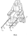
- a plurality of extendable members 30 and 34 are projected successively, as shown in FIG. 4. Referring further to FIG. 4, strut 14 is shown in a fully deployed position, with further forward rotation inhibited by stop 36 . Additionally, extendable members 30 and 34 are shown fully projected such that further tipping of vehicle 10 is prevented. Referring to FIG. 5, the fully deployed position of struts 14 is shown in front view, along with fully projected extendable members 30 and 34 .
- FIG. 6 vehicle 10 is shown tipping in a backwards direction, with strut 16 in the process of rearward deployment and extendable member 40 projected to bring wheel 20 into ground contact to initiate rolling of wheel 20 . Projection of extendable member 40 provides for ground contact of wheel 20 so that vehicle 10 may continue to roll and tipping is inhibited. Actuation of actuator 24 in response to tipping of vehicle 10 is in a manner analogous to that described with respect to strut 14 in reference to FIGS. 1-5. In FIG. 7, strut 16 is shown fully deployed, with further rotation inhibited by stop 42 .
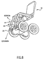
- FIG. 8 shows an alternative embodiment of the invention as implemented on a wheelchair-type vehicle 10 , indicating struts 14 , extendable members 40 and wheels 20 .
Landscapes
- Health & Medical Sciences (AREA)
- Life Sciences & Earth Sciences (AREA)
- Animal Behavior & Ethology (AREA)
- General Health & Medical Sciences (AREA)
- Public Health (AREA)
- Veterinary Medicine (AREA)
- Engineering & Computer Science (AREA)
- Mechanical Engineering (AREA)
- Vehicle Body Suspensions (AREA)
- Handcart (AREA)
- Body Structure For Vehicles (AREA)
- Dental Tools And Instruments Or Auxiliary Dental Instruments (AREA)
- Details Of Aerials (AREA)
- Fittings On The Vehicle Exterior For Carrying Loads, And Devices For Holding Or Mounting Articles (AREA)
- Steroid Compounds (AREA)
- Vehicle Cleaning, Maintenance, Repair, Refitting, And Outriggers (AREA)
- Automatic Cycles, And Cycles In General (AREA)
- Toys (AREA)
- Vending Machines For Individual Products (AREA)
- Constitution Of High-Frequency Heating (AREA)
- Centrifugal Separators (AREA)
Abstract
Description
Claims (5)
- A vehicle with a centre of mass and a direction of travel, the vehicle having a frame (10) and a pair of wheels (12) rotating in laterally spaced planes, the vehicle being supported on the pair of wheels (12) which provide ground contact for the vehicle, the vehicle in use capable of being balanced only on the pair of wheels (12), wherein the vehicle comprises:a strut (16) coupled to the frame in such a manner as to permit rotation of the strut from a retracted position to a deployed position about an axis, the axis having a component perpendicular to the direction of travel of the vehicle;a wheel (18) mounted to an end of the strut;a sensor responsive to a moment of the centre of mass of the vehicle about the ground contact;an actuator for rotating the strut from the retracted position to the deployed position; anda controller including a microprocessor, in communication with the sensor, for activating the actuator in response to a sensed tilt.
- A vehicle according to claim 1, further comprising an engagement mechanism for bringing the wheel mounted to the end of the strut into ground contact.
- A vehicle according to claim 2, wherein the engagement mechanism is provided by an extendable member (30) coupled to said strut.
- A vehicle according to claim 3, wherein said extendable member (30) is an arm received into a sleeve in said strut.
- A vehicle according to any preceding claim, wherein the sensor is an inclinometer.
Applications Claiming Priority (3)
| Application Number | Priority Date | Filing Date | Title |
|---|---|---|---|
| US2187296P | 1996-07-17 | 1996-07-17 | |
| US21872P | 1996-07-17 | ||
| PCT/US1997/012145 WO1998002122A1 (en) | 1996-07-17 | 1997-07-14 | Anti-tipping mechanism |
Publications (2)
| Publication Number | Publication Date |
|---|---|
| EP0912154A1 EP0912154A1 (en) | 1999-05-06 |
| EP0912154B1 true EP0912154B1 (en) | 2004-10-20 |
Family
ID=21806608
Family Applications (1)
| Application Number | Title | Priority Date | Filing Date |
|---|---|---|---|
| EP97932588A Expired - Lifetime EP0912154B1 (en) | 1996-07-17 | 1997-07-14 | Anti-tipping mechanism |
Country Status (14)
| Country | Link |
|---|---|
| US (1) | US6062600A (en) |
| EP (1) | EP0912154B1 (en) |
| JP (1) | JP2000514680A (en) |
| CN (1) | CN1163209C (en) |
| AT (1) | ATE279895T1 (en) |
| AU (1) | AU710104B2 (en) |
| BR (1) | BR9710331A (en) |
| CA (1) | CA2260220C (en) |
| DE (1) | DE69731296T2 (en) |
| IL (1) | IL127778A (en) |
| NO (1) | NO321573B1 (en) |
| RU (1) | RU2190382C2 (en) |
| TW (1) | TW353619B (en) |
| WO (1) | WO1998002122A1 (en) |
Cited By (1)
| Publication number | Priority date | Publication date | Assignee | Title |
|---|---|---|---|---|
| EP3446669A1 (en) | 2017-08-25 | 2019-02-27 | Lukas Rigler | Support system for an electronically self-balancing wheelchair |
Families Citing this family (104)
| Publication number | Priority date | Publication date | Assignee | Title |
|---|---|---|---|---|
| AU728453B2 (en) * | 1995-02-03 | 2001-01-11 | Deka Research And Development Corporation | Indication system for a vehicle |
| WO1998038958A1 (en) * | 1997-03-05 | 1998-09-11 | Massachusetts Institute Of Technology | A reconfigurable footprint mechanism for omnidirectional vehicles |
| GB2331963B (en) * | 1997-10-22 | 2002-01-23 | Andrew Paul Ockwell | A pushchair stand and brake |
| US6530598B1 (en) * | 1999-04-29 | 2003-03-11 | Ronald Lee Kirby | Anti-tip devices for wheeled conveyances including wheelchairs and method related thereto |
| US6405816B1 (en) | 1999-06-03 | 2002-06-18 | Deka Products Limited Partnership | Mechanical improvements to a personal vehicle |
| US7275607B2 (en) | 1999-06-04 | 2007-10-02 | Deka Products Limited Partnership | Control of a personal transporter based on user position |
| JP4769915B2 (en) * | 2000-05-01 | 2011-09-07 | 独立行政法人労働安全衛生総合研究所 | Fall shock absorber for wheelchair |
| JP3527686B2 (en) | 2000-05-08 | 2004-05-17 | 株式会社カワムラサイクル | Wheelchair fall prevention mechanism and wheelchair |
| WO2001094185A1 (en) | 2000-06-09 | 2001-12-13 | Shimadzu Mectem, Inc. | Walker |
| US6554086B1 (en) * | 2000-10-27 | 2003-04-29 | Invacare Corporation | Obstacle traversing wheelchair |
| US7040429B2 (en) * | 2001-10-10 | 2006-05-09 | Invacare Corporation | Wheelchair suspension |
| US7066290B2 (en) * | 2001-10-19 | 2006-06-27 | Invacare Corp. | Wheelchair suspension having pivotal motor mount |
| US20040032119A1 (en) * | 2002-05-29 | 2004-02-19 | Sy Tran | Control of an anti-tip wheel in wheelchairs |
| AU2003247972A1 (en) | 2002-07-12 | 2004-02-02 | Deka Products Limited Partnership | Control of a transporter based on attitude |
| JP2004074814A (en) * | 2002-08-09 | 2004-03-11 | Matsushita Electric Works Ltd | Moving equipment for man |
| US6776430B2 (en) | 2002-09-09 | 2004-08-17 | Pride Mobility Products Corporation | Stabilizing system for a reclinable wheelchair |
| US7011171B1 (en) * | 2002-10-08 | 2006-03-14 | Poulter Andrew R | Rugged terrain robot |
| US7293801B2 (en) * | 2003-08-18 | 2007-11-13 | Invacare Corporation | Self-stabilizing suspension for wheeled vehicles |
| US11213441B2 (en) | 2002-10-25 | 2022-01-04 | Invacare Corporation | Suspension for wheeled vehicles |
| JP4422415B2 (en) * | 2003-01-17 | 2010-02-24 | トヨタ自動車株式会社 | Motorcycle |
| NL1023378C2 (en) * | 2003-05-09 | 2004-11-15 | Movingpeople Net Internat B V | Wheelchair. |
| US7311329B2 (en) | 2003-05-23 | 2007-12-25 | Pride Mobility Products Corporation | Anti-tip wheel for a wheelchair |
| US7232008B2 (en) * | 2003-10-08 | 2007-06-19 | Pride Mobility Products Corporation | Active anti-tip wheels for power wheelchair |
| JP4333398B2 (en) * | 2004-02-17 | 2009-09-16 | トヨタ車体株式会社 | Wheelbase variable vehicle |
| DE102004010089A1 (en) * | 2004-02-27 | 2005-09-15 | Losch Airport Equipment Gmbh | Transport vehicle for wheelchairs |
| US20060076748A1 (en) * | 2004-10-08 | 2006-04-13 | Sunrise Medical Hhg Inc. | Wheelchair with damping mechanism |
| US7360792B2 (en) * | 2004-10-20 | 2008-04-22 | Pride Mobility Products Corporation | Power wheelchair |
| US20060091663A1 (en) * | 2004-10-21 | 2006-05-04 | Sunrise Medical Hhg Inc. | Wheelchair with telescopic anti-tip wheel |
| CN100557539C (en) * | 2005-07-26 | 2009-11-04 | 松下电器产业株式会社 | Inverted two-wheel walking robot and control method thereof |
| US7854435B2 (en) * | 2005-10-06 | 2010-12-21 | Colin Alan Campbell | Wheel mechanism |
| JP4556831B2 (en) * | 2005-10-13 | 2010-10-06 | トヨタ自動車株式会社 | Traveling apparatus and control method thereof |
| US7744331B2 (en) * | 2006-01-26 | 2010-06-29 | Xerox Corporation | Transport vehicle and method |
| JP4291822B2 (en) * | 2006-02-03 | 2009-07-08 | トヨタ自動車株式会社 | Inverted wheel type traveling body |
| JP2007237750A (en) * | 2006-03-03 | 2007-09-20 | Toyota Motor Corp | Inverted pendulum type moving body |
| DE102006013910B3 (en) * | 2006-03-25 | 2007-07-26 | Otto Bock Healthcare Ip Gmbh & Co. Kg | Wheelchair, with a rear structure to prevent tipping backwards, has swing struts with support rollers at the ends of the rear axle to swing out for use and fold inwards when not required |
| US7686319B1 (en) * | 2006-05-31 | 2010-03-30 | Robert M Fink | Double amputee conveyance |
| CN101135522B (en) * | 2006-08-30 | 2011-02-02 | 海尔集团公司 | Integrally cooling compressor warehouse refrigerator with anti-tipping apparatus |
| EP1943995A1 (en) * | 2007-01-12 | 2008-07-16 | Invacare International Sàrl | A wheeled conveyance with suspension arms for wheels |
| ATE493960T1 (en) | 2007-02-08 | 2011-01-15 | Invacare Corp | WHEELCHAIR SUSPENSION |
| DK2340800T3 (en) | 2007-02-14 | 2013-07-22 | Invacare Corp | STABILITY MANAGEMENT SYSTEM |
| JP4858847B2 (en) * | 2007-03-29 | 2012-01-18 | 株式会社エクォス・リサーチ | vehicle |
| WO2008120507A1 (en) * | 2007-03-29 | 2008-10-09 | Equos Research Co., Ltd. | Vehicle |
| JP5004003B2 (en) * | 2007-03-29 | 2012-08-22 | 株式会社エクォス・リサーチ | vehicle |
| JP5024662B2 (en) * | 2007-03-29 | 2012-09-12 | 株式会社エクォス・リサーチ | vehicle |
| JP4924179B2 (en) * | 2007-04-25 | 2012-04-25 | トヨタ自動車株式会社 | Inverted wheel type moving body and control method thereof |
| JP4973303B2 (en) * | 2007-04-27 | 2012-07-11 | トヨタ自動車株式会社 | Inverted type moving body and method for stopping movement of inverted type moving body |
| JP4867823B2 (en) | 2007-07-09 | 2012-02-01 | トヨタ自動車株式会社 | Inverted wheel type moving body and control method thereof |
| JP4681016B2 (en) | 2008-03-10 | 2011-05-11 | 株式会社豊田中央研究所 | Inverted pendulum type wheel moving body |
| JP5158712B2 (en) * | 2008-11-14 | 2013-03-06 | アイシン精機株式会社 | Personal vehicle |
| US8249773B2 (en) | 2008-11-27 | 2012-08-21 | Toyota Jidosha Kabushiki Kaisha | Vehicle and its control method |
| JP5045707B2 (en) * | 2009-05-28 | 2012-10-10 | トヨタ自動車株式会社 | Traveling apparatus, control method thereof, and control program |
| EP3238682A3 (en) | 2009-10-09 | 2018-01-10 | Invacare Corporation | Wheelchair suspension with opposite movement of anti-tip arms |
| US20110204592A1 (en) * | 2010-02-17 | 2011-08-25 | Johansen N Layne | Mobility and Accessibility Device and Lift |
| US8616574B2 (en) * | 2011-09-12 | 2013-12-31 | Donald MONACO | Compact ergonomic mobility chair |
| ITMI20112311A1 (en) * | 2011-12-19 | 2013-06-20 | Gm Italia S R L | MOTORIZED WHEELCHAIR |
| AU2015249084B2 (en) * | 2012-02-09 | 2017-09-07 | Omeo Group Limited | Powered Mobility Device with Tilt Mechanism Having Multiple Pivots |
| NZ628837A (en) | 2012-02-15 | 2016-10-28 | Invacare Corp | Wheelchair suspension |
| JP5922489B2 (en) * | 2012-05-14 | 2016-05-24 | 本田技研工業株式会社 | Inverted pendulum type vehicle |
| CN103010190B (en) * | 2012-12-14 | 2014-11-12 | 盐城市盐海拖拉机制造有限公司 | Safety brake device of walking tractor |
| JP5979322B2 (en) * | 2013-12-25 | 2016-08-24 | 株式会社村田製作所 | Wheelbarrow |
| JP6179398B2 (en) * | 2013-12-27 | 2017-08-16 | トヨタ自動車株式会社 | Coaxial motorcycle control method |
| US9186289B2 (en) * | 2014-04-14 | 2015-11-17 | James Nicholas | Anti-tipping safety device |
| WO2015199048A1 (en) * | 2014-06-23 | 2015-12-30 | 株式会社村田製作所 | Pushcart |
| DE102014113278B4 (en) * | 2014-09-15 | 2016-08-25 | Freee Mobility Gmbh | Support system, electronically self-balanced wheelchair, method of controlling a support system and conversion kit |
| US9682603B2 (en) * | 2014-10-10 | 2017-06-20 | Max Mobility, Llc | System and method for adjusting a wheelchair seat |
| US9889562B1 (en) | 2015-10-16 | 2018-02-13 | X Development Llc | Smart kickstand for balancing a mobile robotic arm |
| WO2017147347A1 (en) * | 2016-02-23 | 2017-08-31 | Deka Products Limited Partnership | Mobility device control system |
| US10926756B2 (en) | 2016-02-23 | 2021-02-23 | Deka Products Limited Partnership | Mobility device |
| US10908045B2 (en) | 2016-02-23 | 2021-02-02 | Deka Products Limited Partnership | Mobility device |
| US11399995B2 (en) | 2016-02-23 | 2022-08-02 | Deka Products Limited Partnership | Mobility device |
| CA3287428A1 (en) | 2016-04-14 | 2025-10-31 | Deka Products Limited Partnership | User control device for a transporter |
| MX2023008304A (en) * | 2016-05-20 | 2024-02-29 | Deka Products Lp | Mobility device. |
| USD837323S1 (en) | 2018-01-03 | 2019-01-01 | Razor Usa Llc | Two wheeled board |
| USD840872S1 (en) | 2016-07-20 | 2019-02-19 | Razor Usa Llc | Two wheeled board |
| USD803963S1 (en) | 2016-07-20 | 2017-11-28 | Razor Usa Llc | Two wheeled board |
| USD941948S1 (en) | 2016-07-20 | 2022-01-25 | Razor Usa Llc | Two wheeled board |
| USD807457S1 (en) | 2016-07-20 | 2018-01-09 | Razor Usa Llc | Two wheeled board |
| CN106240698B (en) * | 2016-08-01 | 2018-11-06 | 林允杜 | A kind of high security high stability balance car |
| US10772774B2 (en) | 2016-08-10 | 2020-09-15 | Max Mobility, Llc | Self-balancing wheelchair |
| EP3311786A1 (en) * | 2016-10-21 | 2018-04-25 | Airbus Defence and Space Limited | Vehicle wheel assembly |
| JP6746521B2 (en) * | 2017-03-16 | 2020-08-26 | Whill株式会社 | Electric mobility and its disassembly method |
| US12227257B2 (en) | 2017-04-01 | 2025-02-18 | Razor Usa Llc | Electric balance vehicles |
| USD829612S1 (en) | 2017-05-20 | 2018-10-02 | Deka Products Limited Partnership | Set of toggles |
| USD846452S1 (en) | 2017-05-20 | 2019-04-23 | Deka Products Limited Partnership | Display housing |
| USD1047785S1 (en) | 2017-05-20 | 2024-10-22 | Deka Products Limited Partnership | Toggle control device |
| CN107361931A (en) * | 2017-08-17 | 2017-11-21 | 福尔智能科技南通有限公司 | A kind of Anti-inclining Wheel-chair type bed |
| JP7798473B2 (en) | 2017-12-22 | 2026-01-14 | レイザー・ユーエスエー・エルエルシー | Electric balancing vehicle |
| CN108186220A (en) * | 2017-12-22 | 2018-06-22 | 江阴市新盛医疗器材设备有限公司 | A kind of falling-resistant wheel |
| FR3079139A1 (en) * | 2018-03-26 | 2019-09-27 | Vincent Poullet | WHEELCHAIR WITH PILOT STABILIZER ELEMENT |
| ES3061234T3 (en) | 2018-06-07 | 2026-03-31 | Deka Products Lp | System and method for distributed utility service execution |
| US11602468B2 (en) | 2018-06-12 | 2023-03-14 | Rehabilitation Institute Of Chicago | Methods and apparatus for increasing the effectiveness of wheelchair training |
| EP3812256B1 (en) | 2018-06-20 | 2022-08-17 | Honda Motor Co., Ltd. | Mobile body |
| CN108652848B (en) * | 2018-06-21 | 2019-12-03 | 朱全祥 | One kind can barrier-jump hinder wheelchair |
| CN109431700B (en) * | 2018-11-02 | 2020-04-24 | 定远县中林机械技术有限公司 | Multifunctional wheelchair |
| CN109646756B (en) * | 2018-12-29 | 2021-01-29 | 中国人民解放军陆军军医大学第一附属医院 | Gravity type anti-toppling infusion vehicle |
| US10905607B2 (en) * | 2019-01-29 | 2021-02-02 | Toyota Motor North America, Inc. | Modular power base arrangement |
| CN111184609A (en) * | 2019-02-25 | 2020-05-22 | 永康国科康复工程技术有限公司 | a walking aid |
| JP7125236B2 (en) * | 2019-04-05 | 2022-08-24 | 国立大学法人 東京大学 | running gear |
| CN111803337A (en) * | 2019-04-12 | 2020-10-23 | 曹可瀚 | Anti-tipping walking aid and method of use |
| US11903887B2 (en) | 2020-02-25 | 2024-02-20 | Invacare Corporation | Wheelchair and suspension systems |
| JP7009535B2 (en) * | 2020-03-16 | 2022-02-10 | 本田技研工業株式会社 | Vehicles and vehicle control methods |
| FR3116792B1 (en) * | 2020-11-30 | 2022-11-04 | Univ Versailles Saint Quentin En Yvelines | Aid for moving a load |
| CN112837498A (en) * | 2021-03-01 | 2021-05-25 | 国网冀北电力有限公司唐山供电公司 | A safety protection device for line maintenance and using method thereof |
| CN114587809A (en) * | 2022-03-29 | 2022-06-07 | 中南大学湘雅二医院 | A new type of special wheelchair for cardiology nursing to prevent patients from falling |
Family Cites Families (27)
| Publication number | Priority date | Publication date | Assignee | Title |
|---|---|---|---|---|
| DE50975C (en) * | FR. A. ZSCHIESCHE in Cottbus | Device for preventing prams from falling | ||
| US1591529A (en) * | 1922-05-12 | 1926-07-06 | Roger S S Guerber | Invalid chair |
| US2402322A (en) * | 1945-04-25 | 1946-06-18 | Jr Andrew J Flynn | Antitipping device for infants' vehicles |
| US3397898A (en) * | 1967-02-06 | 1968-08-20 | Caterpillar Tractor Co | Stabilizer for motor vehicle |
| US3804435A (en) * | 1971-09-15 | 1974-04-16 | Caterpillar Tractor Co | Vehicle roll-over safety apparatus |
| JPS5144534Y2 (en) * | 1973-04-17 | 1976-10-28 | ||
| US3848883A (en) * | 1973-08-08 | 1974-11-19 | S Breacain | Wheelchair anti-tip apparatus |
| JPS6033172A (en) * | 1983-08-05 | 1985-02-20 | Hiroyasu Funakubo | Travelling and walking vehicle |
| US4691798A (en) * | 1985-10-10 | 1987-09-08 | Engelbach Thomas S | System for automatically preventing turnover of two wheeled vehicles |
| WO1988003012A1 (en) * | 1986-10-24 | 1988-05-05 | Comporgan Rendszerház K.V. | Wheel-chair for the handicapped, in particular for negotiating stairs |
| JPH048061Y2 (en) * | 1987-01-16 | 1992-03-02 | ||
| DE3800476A1 (en) * | 1988-01-11 | 1989-07-20 | Anschuetz & Co Gmbh | METHOD FOR STABILIZING A UNI-AXLE CYCLING VEHICLE AND VEHICLE STABILIZED BY THIS METHOD |
| SU1634276A1 (en) * | 1988-02-01 | 1991-03-15 | М.С.Исламов | Wheeled chair |
| SU1586706A1 (en) * | 1988-06-13 | 1990-08-23 | Иркутский Авиационный Завод Им.60-Летия Союза Сср | Invalid wheel-chair |
| IL91588A (en) * | 1989-09-10 | 1994-10-07 | Propel Partnership 1987 | Electric drive attachment for wheelchairs |
| SU1752386A1 (en) * | 1990-01-31 | 1992-08-07 | А.Д.Лебедев | Wheeled chair for invalids |
| EP0557440B1 (en) * | 1990-11-14 | 1998-07-15 | Invacare Corporation | Attended to self-propelled convertible pivoting wheelchair |
| US5421598A (en) * | 1991-04-26 | 1995-06-06 | Everest & Jennings International, Ltd. | Modular wheelchair |
| JP2530127Y2 (en) * | 1991-06-07 | 1997-03-26 | セイレイ工業株式会社 | Fall prevention mechanism for aerial work vehicles |
| JPH0582345U (en) * | 1992-04-09 | 1993-11-09 | 中川研材株式会社 | Chair for double bed |
| US5401055A (en) * | 1992-05-28 | 1995-03-28 | Pham; Roger | Space efficient center tracking vehicle |
| DE4231876C1 (en) * | 1992-09-23 | 1994-04-21 | Christian Klepsch | Wheelchair for negotiating steps - has seat gondola rotatably located on shaft at ends of which two large dia. drive wheels are fixed |
| DE4334069A1 (en) * | 1993-06-21 | 1995-04-13 | Zeiss Carl Fa | Balanced tripod |
| JPH0731656A (en) * | 1993-07-23 | 1995-02-03 | Kazuo Tsuruta | Wheel chair wherein seat part can be inclined and elevated and bathtab unit |
| US5513716A (en) * | 1994-05-09 | 1996-05-07 | Trustees Of The University Of Pennsylvania | Adaptive mobility system |
| ATE288248T1 (en) * | 1994-11-18 | 2005-02-15 | Degonda Rehab Sa | CHAIR WITH WHEELS TO TRANSPORT OR ASSIST AT LEAST ONE USER, PARTICULARLY A DISABLED PERSON |
| CA2211738C (en) * | 1995-02-03 | 2003-09-16 | Deka Products Limited Partnership | Transportation vehicles and methods |
-
1997
- 1997-07-14 EP EP97932588A patent/EP0912154B1/en not_active Expired - Lifetime
- 1997-07-14 BR BR9710331A patent/BR9710331A/en not_active IP Right Cessation
- 1997-07-14 DE DE69731296T patent/DE69731296T2/en not_active Expired - Lifetime
- 1997-07-14 US US08/892,566 patent/US6062600A/en not_active Expired - Lifetime
- 1997-07-14 AT AT97932588T patent/ATE279895T1/en not_active IP Right Cessation
- 1997-07-14 WO PCT/US1997/012145 patent/WO1998002122A1/en not_active Ceased
- 1997-07-14 CA CA002260220A patent/CA2260220C/en not_active Expired - Fee Related
- 1997-07-14 IL IL12777897A patent/IL127778A/en not_active IP Right Cessation
- 1997-07-14 RU RU99103214/14A patent/RU2190382C2/en not_active IP Right Cessation
- 1997-07-14 AU AU40004/97A patent/AU710104B2/en not_active Expired
- 1997-07-14 CN CNB97196386XA patent/CN1163209C/en not_active Expired - Fee Related
- 1997-07-14 JP JP10506194A patent/JP2000514680A/en active Pending
- 1997-07-30 TW TW086110288A patent/TW353619B/en active
-
1998
- 1998-12-22 NO NO19986067A patent/NO321573B1/en not_active IP Right Cessation
Cited By (1)
| Publication number | Priority date | Publication date | Assignee | Title |
|---|---|---|---|---|
| EP3446669A1 (en) | 2017-08-25 | 2019-02-27 | Lukas Rigler | Support system for an electronically self-balancing wheelchair |
Also Published As
| Publication number | Publication date |
|---|---|
| JP2000514680A (en) | 2000-11-07 |
| IL127778A (en) | 2004-09-27 |
| CA2260220A1 (en) | 1998-01-22 |
| NO986067L (en) | 1999-01-29 |
| AU4000497A (en) | 1998-02-09 |
| BR9710331A (en) | 1999-08-17 |
| WO1998002122A1 (en) | 1998-01-22 |
| RU2190382C2 (en) | 2002-10-10 |
| DE69731296D1 (en) | 2004-11-25 |
| AU710104B2 (en) | 1999-09-16 |
| ATE279895T1 (en) | 2004-11-15 |
| CN1163209C (en) | 2004-08-25 |
| CA2260220C (en) | 2006-05-16 |
| DE69731296T2 (en) | 2005-11-17 |
| US6062600A (en) | 2000-05-16 |
| NO321573B1 (en) | 2006-06-06 |
| IL127778A0 (en) | 1999-10-28 |
| EP0912154A1 (en) | 1999-05-06 |
| CN1225004A (en) | 1999-08-04 |
| NO986067D0 (en) | 1998-12-22 |
| TW353619B (en) | 1999-03-01 |
Similar Documents
| Publication | Publication Date | Title |
|---|---|---|
| AU710104B2 (en) | Anti-tipping mechanism | |
| US20240326944A1 (en) | Dynamically balanced in-line wheel vehicle | |
| US5316328A (en) | Bumper mounted anti-tip stabilizers for chair-mounting vehicles utilized by physically disadvantaged persons and others desiring mobility assistance, and methods of stabilizing such vehicles | |
| US6547026B2 (en) | Safety separation system | |
| US5899475A (en) | Vehicle having wheels and castors | |
| US20010014569A1 (en) | Fun-kart with two powered wheels | |
| US7810591B2 (en) | Traveling device | |
| JP2008194466A (en) | Safety separation system | |
| US20010026079A1 (en) | Vehicle embodying a system for protection in case of impact | |
| GB2390065A (en) | An active level control system for electrically propelled vehicles | |
| EP1475063B1 (en) | Wheel Chair | |
| CN218839657U (en) | Rollover-preventing child sliding vehicle | |
| GB2199291A (en) | Wheelchair with kerb climbing ability | |
| AU732256B2 (en) | Vehicle | |
| GB2318555A (en) | Vehicle for leisure or competitive use | |
| MXPA00003635A (en) | Safety separation system | |
| JP3008997B2 (en) | Electric tricycle | |
| JP2001314450A (en) | Tip-resistant mechanism of wheelchair and wheelchair |
Legal Events
| Date | Code | Title | Description |
|---|---|---|---|
| PUAI | Public reference made under article 153(3) epc to a published international application that has entered the european phase |
Free format text: ORIGINAL CODE: 0009012 |
|
| 17P | Request for examination filed |
Effective date: 19981230 |
|
| AK | Designated contracting states |
Kind code of ref document: A1 Designated state(s): AT BE CH DE DK ES FI FR GB GR IE IT LI LU MC NL PT SE |
|
| RIN1 | Information on inventor provided before grant (corrected) |
Inventor name: SMITH, STANLEY, B., III Inventor name: LANGENFELD, CHRISTOPHER, C. Inventor name: AMBROGI, ROBERT Inventor name: KAMEN, DEAN, L. |
|
| 17Q | First examination report despatched |
Effective date: 20011024 |
|
| GRAP | Despatch of communication of intention to grant a patent |
Free format text: ORIGINAL CODE: EPIDOSNIGR1 |
|
| GRAS | Grant fee paid |
Free format text: ORIGINAL CODE: EPIDOSNIGR3 |
|
| GRAA | (expected) grant |
Free format text: ORIGINAL CODE: 0009210 |
|
| AK | Designated contracting states |
Kind code of ref document: B1 Designated state(s): AT BE CH DE DK ES FI FR GB GR IE IT LI LU MC NL PT SE |
|
| PG25 | Lapsed in a contracting state [announced via postgrant information from national office to epo] |
Ref country code: NL Free format text: LAPSE BECAUSE OF FAILURE TO SUBMIT A TRANSLATION OF THE DESCRIPTION OR TO PAY THE FEE WITHIN THE PRESCRIBED TIME-LIMIT Effective date: 20041020 Ref country code: LI Free format text: LAPSE BECAUSE OF FAILURE TO SUBMIT A TRANSLATION OF THE DESCRIPTION OR TO PAY THE FEE WITHIN THE PRESCRIBED TIME-LIMIT Effective date: 20041020 Ref country code: IT Free format text: LAPSE BECAUSE OF FAILURE TO SUBMIT A TRANSLATION OF THE DESCRIPTION OR TO PAY THE FEE WITHIN THE PRE;WARNING: LAPSES OF ITALIAN PATENTS WITH EFFECTIVE DATE BEFORE 2007 MAY HAVE OCCURRED AT ANY TIME BEFORE 2007. THE CORRECT EFFECTIVE DATE MAY BE DIFFERENT FROM THE ONE RECORDED.SCRIBED TIME-LIMIT Effective date: 20041020 Ref country code: FI Free format text: LAPSE BECAUSE OF FAILURE TO SUBMIT A TRANSLATION OF THE DESCRIPTION OR TO PAY THE FEE WITHIN THE PRESCRIBED TIME-LIMIT Effective date: 20041020 Ref country code: CH Free format text: LAPSE BECAUSE OF FAILURE TO SUBMIT A TRANSLATION OF THE DESCRIPTION OR TO PAY THE FEE WITHIN THE PRESCRIBED TIME-LIMIT Effective date: 20041020 Ref country code: BE Free format text: LAPSE BECAUSE OF FAILURE TO SUBMIT A TRANSLATION OF THE DESCRIPTION OR TO PAY THE FEE WITHIN THE PRESCRIBED TIME-LIMIT Effective date: 20041020 Ref country code: AT Free format text: LAPSE BECAUSE OF FAILURE TO SUBMIT A TRANSLATION OF THE DESCRIPTION OR TO PAY THE FEE WITHIN THE PRESCRIBED TIME-LIMIT Effective date: 20041020 |
|
| REG | Reference to a national code |
Ref country code: GB Ref legal event code: FG4D |
|
| REG | Reference to a national code |
Ref country code: CH Ref legal event code: EP |
|
| REG | Reference to a national code |
Ref country code: IE Ref legal event code: FG4D |
|
| REF | Corresponds to: |
Ref document number: 69731296 Country of ref document: DE Date of ref document: 20041125 Kind code of ref document: P |
|
| PG25 | Lapsed in a contracting state [announced via postgrant information from national office to epo] |
Ref country code: SE Free format text: LAPSE BECAUSE OF FAILURE TO SUBMIT A TRANSLATION OF THE DESCRIPTION OR TO PAY THE FEE WITHIN THE PRESCRIBED TIME-LIMIT Effective date: 20050120 Ref country code: GR Free format text: LAPSE BECAUSE OF FAILURE TO SUBMIT A TRANSLATION OF THE DESCRIPTION OR TO PAY THE FEE WITHIN THE PRESCRIBED TIME-LIMIT Effective date: 20050120 Ref country code: DK Free format text: LAPSE BECAUSE OF FAILURE TO SUBMIT A TRANSLATION OF THE DESCRIPTION OR TO PAY THE FEE WITHIN THE PRESCRIBED TIME-LIMIT Effective date: 20050120 |
|
| PG25 | Lapsed in a contracting state [announced via postgrant information from national office to epo] |
Ref country code: ES Free format text: LAPSE BECAUSE OF FAILURE TO SUBMIT A TRANSLATION OF THE DESCRIPTION OR TO PAY THE FEE WITHIN THE PRESCRIBED TIME-LIMIT Effective date: 20050131 |
|
| REG | Reference to a national code |
Ref country code: CH Ref legal event code: PL |
|
| NLV1 | Nl: lapsed or annulled due to failure to fulfill the requirements of art. 29p and 29m of the patents act | ||
| ET | Fr: translation filed | ||
| PG25 | Lapsed in a contracting state [announced via postgrant information from national office to epo] |
Ref country code: LU Free format text: LAPSE BECAUSE OF NON-PAYMENT OF DUE FEES Effective date: 20050714 Ref country code: IE Free format text: LAPSE BECAUSE OF NON-PAYMENT OF DUE FEES Effective date: 20050714 |
|
| PG25 | Lapsed in a contracting state [announced via postgrant information from national office to epo] |
Ref country code: MC Free format text: LAPSE BECAUSE OF NON-PAYMENT OF DUE FEES Effective date: 20050731 |
|
| PLBE | No opposition filed within time limit |
Free format text: ORIGINAL CODE: 0009261 |
|
| STAA | Information on the status of an ep patent application or granted ep patent |
Free format text: STATUS: NO OPPOSITION FILED WITHIN TIME LIMIT |
|
| 26N | No opposition filed |
Effective date: 20050721 |
|
| REG | Reference to a national code |
Ref country code: IE Ref legal event code: MM4A |
|
| PG25 | Lapsed in a contracting state [announced via postgrant information from national office to epo] |
Ref country code: PT Free format text: LAPSE BECAUSE OF NON-PAYMENT OF DUE FEES Effective date: 20050320 |
|
| PGFP | Annual fee paid to national office [announced via postgrant information from national office to epo] |
Ref country code: FR Payment date: 20100805 Year of fee payment: 14 Ref country code: DE Payment date: 20100723 Year of fee payment: 14 |
|
| PGFP | Annual fee paid to national office [announced via postgrant information from national office to epo] |
Ref country code: GB Payment date: 20100722 Year of fee payment: 14 |
|
| GBPC | Gb: european patent ceased through non-payment of renewal fee |
Effective date: 20110714 |
|
| REG | Reference to a national code |
Ref country code: FR Ref legal event code: ST Effective date: 20120330 |
|
| PG25 | Lapsed in a contracting state [announced via postgrant information from national office to epo] |
Ref country code: FR Free format text: LAPSE BECAUSE OF NON-PAYMENT OF DUE FEES Effective date: 20110801 Ref country code: DE Free format text: LAPSE BECAUSE OF NON-PAYMENT OF DUE FEES Effective date: 20120201 |
|
| REG | Reference to a national code |
Ref country code: DE Ref legal event code: R119 Ref document number: 69731296 Country of ref document: DE Effective date: 20120201 |
|
| PG25 | Lapsed in a contracting state [announced via postgrant information from national office to epo] |
Ref country code: GB Free format text: LAPSE BECAUSE OF NON-PAYMENT OF DUE FEES Effective date: 20110714 |