EP0912127B1 - Shower apparatus comprising multiple shower heads and diverter - Google Patents
Shower apparatus comprising multiple shower heads and diverter Download PDFInfo
- Publication number
- EP0912127B1 EP0912127B1 EP97932902A EP97932902A EP0912127B1 EP 0912127 B1 EP0912127 B1 EP 0912127B1 EP 97932902 A EP97932902 A EP 97932902A EP 97932902 A EP97932902 A EP 97932902A EP 0912127 B1 EP0912127 B1 EP 0912127B1
- Authority
- EP
- European Patent Office
- Prior art keywords
- shower
- diverter
- shower head
- disc
- apertures
- Prior art date
- Legal status (The legal status is an assumption and is not a legal conclusion. Google has not performed a legal analysis and makes no representation as to the accuracy of the status listed.)
- Expired - Lifetime
Links
Images


Classifications
-
- E—FIXED CONSTRUCTIONS
- E03—WATER SUPPLY; SEWERAGE
- E03C—DOMESTIC PLUMBING INSTALLATIONS FOR FRESH WATER OR WASTE WATER; SINKS
- E03C1/00—Domestic plumbing installations for fresh water or waste water; Sinks
- E03C1/02—Plumbing installations for fresh water
- E03C1/04—Water-basin installations specially adapted to wash-basins or baths
- E03C1/0408—Water installations especially for showers
Definitions
- the present invention relates to improvements in or relating to shower apparatus.
- Conventional shower apparatus usually housed in a shower enclosure or above a bath, generally include a shower head attached to one end of a conduit means.
- the other end of the conduit means is in communication with a mixing means which, in turn, is attached to a hot and cold water supply.
- the mixing means enables the hot and cold water to be mixed so that the water passing through the shower head, via the conduit means, onto the user, is of a desired temperature previously selected by the user.
- the major disadvantage of such conventional shower apparatus is that the user, in order to direct the flow of water onto various parts of his/her body, either has to move in relation to the shower head, or alternatively, has to remove the shower head from its associated holder and move the shower head around his/her body, whilst holding same.
- US-A-5121511 discloses a shower apparatus comprising a plurality of shower heads each attached to respective conduit means, each of the conduit means also being in communication with a mixing means which is in communication with a hot and cold water supply, wherein diverter means are located between the mixing means and each of the conduit means for diverting water originating from the mixing means either to one shower head at a time, or alternatively, to more than one shower head at the same time.
- the present invention provides a shower apparatus comprising a plurality of shower heads whereby water can be directed either solely through one of said shower heads onto the user, or alternatively, through more than one shower head at the same time onto the user, thereby providing a very flexible shower environment and experience, permitting the user to easily and quickly move the direction of the water hitting them, rather than having to move in relation to the shower heads or hold a flexible shower head and move it around their body.
- a shower apparatus comprising a plurality of shower heads each attached to respective conduit means, each of the conduit means also being in communication with a mixing means which is in communication with a hot and cold water supply, in that diverter means being located between the mixing means and each of the conduit means for diverting water originating from the mixing means either to one shower head at a time, or alternatively, to more than one shower head at the same time characterised in that the diverter means comprises a valve means in the form of a ceramic disc diverter valve means comprising a valve housing, a first static disc having a plurality of apertures provided therein, a second rotating disc having a single aperture therein, the number of apertures in the first static disc corresponding to the number of shower heads utilised, the location of the apertures in such discs being so arranged and/or the shape of the discs being so designed, that, when the rotating disc is rotated it is possible to divert water either to one of the shower heads at a time, or alternatively, to more than one shower head
- said shower apparatus is preferably in the form of a shower column, which column is preferably provided with four shower heads.
- the diverter means can divert water to each of said shower heads separately, or to more than one, preferably two, shower heads at the same time.
- the shower apparatus includes drainage means to reduce the risk of limescale build up in the shower heads.
- the drainage means is in the form of a linked recess on the surface of the rotating disc which connects the conduits that are not in use at the time, thereby enabling water to drain from one shower head to another and hence, clear all water through the lowest open shower head.
- a shower apparatus of the present invention which comprises four shower heads and diverter means for diverting water originating from the mixing means to one shower head, or to two shower heads at the same time, will now be described by way of example and with reference to the accompanying drawings, in which:
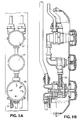
- a shower apparatus 10 comprises four shower heads directable to different parts of the body, namely, an upper shower head 11 directable towards the head of the user (not illustrated), a hand shower head 12 directable towards the hands of the user, a mid-body shower head 13 directable towards the mid-body regions of the user and a lower shower head 14 directable towards the user's feet.
- the upper shower head 11 is attached to first conduit means 21, the hand shower head 12 is attached to second conduit means 22, the mid-body shower head 13 is attached to third conduit means 23 and the lower shower head 14 is attached to fourth conduit means 24.
- Said conduit means 21, 22, 23, 24 are all in communication with the diverter means 15, as illustrated in Fig. 2.
- the diverter means are in the form of a ceramic disc diverter valve 15.
- Said ceramic disc diverter valve comprises a disc carrier 40, a static disc 50, a rotating disc 60, a bush 63, washers 64, a front cover 70, an indenting disc 80, an indenting ball 81 all housed within the diverter body 30.
- a locking ring 82 secures said disc carrier 40, said static disc 50, said rotating disc 60, said bush 63, said washers 64, said front cover 70 within the diverter body 30.
- Said indenting disc 80 and said indenting ball 81 are retained by a circlip 84.
- the ceramic disc diverter valve 15 is in communication with the mixing means 17 via a fifth conduit means 74 attachable to the front cover 70. Since the mixing means 17 is of the conventional type, and is well known in the art, it shall not be described further herein.
- the apertures 51, 52, 53 and 53 on the static disc 50 may be so arranged so that aperture 62 on the rotating disc 60 can be partially aligned with any two of the apertures 51, 52, 53 or 54 which are adjacent to one another.
- the control dial 90 when the control dial 90 is set to the upper shower head 11 and the mid-body shower head 13 the aperture 62 on the rotating disc 60 is partially aligned with the apertures 31 and 33 located in the diverter body 30, the apertures 41 and 43 located in the disc carrier 40 and the aperture 51 and 53 located on the static disc 50.
- the present invention has been described by way of example to a shower apparatus comprising four shower heads and diverter means which is capable of diverting water to one shower head, or to two shower heads at the same time, by changing the orientation, size, shape or number of both the apertures on the static disc 50 and the rotating disc 60, it is possible to divert water originating from the mixing means 17 up to any selected number of shower heads separately or at the same time.
Abstract
Description
Claims (5)
- A shower apparatus (10) comprising a plurality of shower heads (11;12;13;14) each attached to respective conduit means (21;22;23;24), each of the conduit means (21;22;23;24) also being in communication with a mixing means (17) which is in communication with a hot and cold water supply, in that diverter means (15) being located between the mixing means (17) and each of the conduit means (21;22;23;24) for diverting water originating from the mixing means (17) either to one shower head (11;12;13;14) at a time, or alternatively, to more than one shower head (11,13) at the same time characterised in that the diverter means (15) comprises a valve means in the form of a ceramic disc diverter valve means (15) comprising a valve housing (30), a first static disc (50) having a plurality of apertures (51-4) provided therein, a second rotating disc (60) having a single aperture (62) therein, the number of apertures (51-4) in the first static disc (50) corresponding to the number of shower heads (11;12;13;14) utilised, the location of the apertures (51-4;62) in such discs being so arranged and/or the shape of the discs (50;60) being so designed, that, when the rotating disc (60) is rotated it is possible to divert water either to one of the shower heads (11;12;13;14) at a time, or alternatively, to more than one shower head (11,13) at the same time, and operating means (90) for operating the diverter valve means (15).
- A shower apparatus (10) as claimed in claim 1, wherein the shower apparatus (10) is in the form of a shower column.
- A shower apparatus (10) as claimed in claim 1 or 2, wherein the shower apparatus (10) includes 4 shower heads (11;12;13;14).
- A shower apparatus (10) as claimed in any preceding claim, further comprising drainage means.
- A shower apparatus (10) as claimed in claim 4, wherein the drainage means is in the form of a linked recess on the surface of the rotating disc (60) which connects the conduits (21;22;23;24) that are not in use at the same time.
Applications Claiming Priority (3)
| Application Number | Priority Date | Filing Date | Title |
|---|---|---|---|
| GBGB9614776.4A GB9614776D0 (en) | 1996-07-13 | 1996-07-13 | Improvements in or relating to shower apparatus |
| GB9614776 | 1996-07-13 | ||
| PCT/GB1997/001903 WO1998002077A1 (en) | 1996-07-13 | 1997-07-14 | Shower apparatus comprising multiple shower heads and diverter |
Publications (2)
| Publication Number | Publication Date |
|---|---|
| EP0912127A1 EP0912127A1 (en) | 1999-05-06 |
| EP0912127B1 true EP0912127B1 (en) | 2002-11-06 |
Family
ID=10796887
Family Applications (1)
| Application Number | Title | Priority Date | Filing Date |
|---|---|---|---|
| EP97932902A Expired - Lifetime EP0912127B1 (en) | 1996-07-13 | 1997-07-14 | Shower apparatus comprising multiple shower heads and diverter |
Country Status (7)
| Country | Link |
|---|---|
| EP (1) | EP0912127B1 (en) |
| AT (1) | ATE227102T1 (en) |
| AU (1) | AU3627097A (en) |
| DE (1) | DE69716915T2 (en) |
| ES (1) | ES2186904T3 (en) |
| GB (1) | GB9614776D0 (en) |
| WO (1) | WO1998002077A1 (en) |
Cited By (1)
| Publication number | Priority date | Publication date | Assignee | Title |
|---|---|---|---|---|
| US10570592B2 (en) | 2016-04-29 | 2020-02-25 | Fb Global Plumbing Group Llc | Plumbing fixture fitting with diverting system |
Families Citing this family (6)
| Publication number | Priority date | Publication date | Assignee | Title |
|---|---|---|---|---|
| DE10135555B4 (en) * | 2001-07-20 | 2006-08-31 | Hansa Metallwerke Ag | Changeover device for a sanitary device with at least two water consumers |
| ATE375420T1 (en) * | 2003-09-30 | 2007-10-15 | Crs Spa | SHOWER COLUMN |
| DE102004022029B4 (en) * | 2004-05-03 | 2009-07-23 | Grohe Ag | Valve for sanitary facilities |
| DE102007026828A1 (en) * | 2007-06-06 | 2008-12-11 | Grohe Ag | Isolating/reversing valve for sanitary water fittings has a water inlet, water outlets and a disk-control device made from ceramic sealing disks |
| DE102012022212B4 (en) * | 2012-11-07 | 2023-09-21 | Mack & Schneider Gmbh | Disc valve |
| DE102013203946A1 (en) * | 2013-03-07 | 2014-09-11 | Hansgrohe Se | Sanitary line, especially for a shower head |
Family Cites Families (7)
| Publication number | Priority date | Publication date | Assignee | Title |
|---|---|---|---|---|
| WO1987007499A1 (en) * | 1986-06-03 | 1987-12-17 | Guerrero Jacob G | Instant full body hydro massage machine |
| IT1227108B (en) * | 1988-09-28 | 1991-03-15 | Newform S R L | WATER DIVERTER MIXER DEVICE, ESPECIALLY FOR BATHTUB AND SIMILAR |
| US5121511A (en) * | 1989-11-27 | 1992-06-16 | Matsushita Electric Works, Ltd. | Shower device |
| EP0446862A3 (en) * | 1990-03-12 | 1994-06-29 | Toto Ltd | Shower apparatus |
| US5329650A (en) * | 1992-03-06 | 1994-07-19 | Herman Miller, Inc. | Shower stall control column |
| GB2274985B (en) * | 1993-02-12 | 1997-01-22 | Stoves Ltd | Improvements in or relating to shower installations and control units therefor |
| US5561869A (en) * | 1994-07-15 | 1996-10-08 | Sarel; Scott | Shower mounted body washer |
-
1996
- 1996-07-13 GB GBGB9614776.4A patent/GB9614776D0/en active Pending
-
1997
- 1997-07-14 DE DE69716915T patent/DE69716915T2/en not_active Expired - Fee Related
- 1997-07-14 EP EP97932902A patent/EP0912127B1/en not_active Expired - Lifetime
- 1997-07-14 AU AU36270/97A patent/AU3627097A/en not_active Abandoned
- 1997-07-14 AT AT97932902T patent/ATE227102T1/en not_active IP Right Cessation
- 1997-07-14 ES ES97932902T patent/ES2186904T3/en not_active Expired - Lifetime
- 1997-07-14 WO PCT/GB1997/001903 patent/WO1998002077A1/en active IP Right Grant
Cited By (1)
| Publication number | Priority date | Publication date | Assignee | Title |
|---|---|---|---|---|
| US10570592B2 (en) | 2016-04-29 | 2020-02-25 | Fb Global Plumbing Group Llc | Plumbing fixture fitting with diverting system |
Also Published As
| Publication number | Publication date |
|---|---|
| ATE227102T1 (en) | 2002-11-15 |
| ES2186904T3 (en) | 2003-05-16 |
| GB9614776D0 (en) | 1996-09-04 |
| DE69716915T2 (en) | 2003-04-03 |
| AU3627097A (en) | 1998-02-09 |
| EP0912127A1 (en) | 1999-05-06 |
| WO1998002077A1 (en) | 1998-01-22 |
| DE69716915D1 (en) | 2002-12-12 |
Similar Documents
| Publication | Publication Date | Title |
|---|---|---|
| EP0697249B1 (en) | Multi spray pattern shower head | |
| EP0912127B1 (en) | Shower apparatus comprising multiple shower heads and diverter | |
| DE69100077T2 (en) | Faucet tap. | |
| WO1998043009A1 (en) | Fluid valve | |
| EP0808435A4 (en) | Single handle mixing valve with an improved ball valve | |
| BR9608440A (en) | Thermostatic tap mixer valve | |
| US6805151B1 (en) | Valve seats and a ceramic control valve of a faucet | |
| WO2001066986A1 (en) | Delivery control device for the supply of hydraulic apparatuses | |
| GB2315212A (en) | Shower apparatus | |
| IL122709A (en) | Flow control ports for a thermostatic mixing faucet | |
| UA29434C2 (en) | Mixer water tap and ball valve for it (variants) | |
| FR2703425B1 (en) | Distributor valve with built-in flow meter. | |
| USD353187S (en) | Combined faucet and hand shower holder | |
| EP1668195B1 (en) | Shower column | |
| ES1053389U (en) | Switch valve | |
| US3591083A (en) | Domestic water mixing and distribution device | |
| TR199501217A2 (en) | A refined ball valve faucet. | |
| DE50013287D1 (en) | plumbing fixture | |
| KR200230838Y1 (en) | Open / close valve device of booth type shower machine | |
| FR2697312B1 (en) | Interception valve with control handle. | |
| ES1004467U (en) | Improved shower head. (Machine-translation by Google Translate, not legally binding) | |
| ZA987411B (en) | Preparation of 3-Isopropyl-1H-2,1,3-Benzothiadiazin-4 (3H)-One 2,2-Dioxide. | |
| FR2744997B1 (en) | RENES ALLOWING THE BLOCKING OF A RIDER'S HANDS | |
| KR20050064795A (en) | Hot and cool water supply apparatus be mounted inner wall | |
| IT8222686V0 (en) | SINGLE HOLE TAP GROUP WITH SWIVEL SPOUT AND INCORPORATED SPRAY SHOWER. |
Legal Events
| Date | Code | Title | Description |
|---|---|---|---|
| PUAI | Public reference made under article 153(3) epc to a published international application that has entered the european phase |
Free format text: ORIGINAL CODE: 0009012 |
|
| 17P | Request for examination filed |
Effective date: 19990115 |
|
| AK | Designated contracting states |
Kind code of ref document: A1 Designated state(s): AT BE CH DE DK ES FI FR GB GR IE IT LI LU MC NL PT SE |
|
| GRAG | Despatch of communication of intention to grant |
Free format text: ORIGINAL CODE: EPIDOS AGRA |
|
| 17Q | First examination report despatched |
Effective date: 20020111 |
|
| GRAG | Despatch of communication of intention to grant |
Free format text: ORIGINAL CODE: EPIDOS AGRA |
|
| GRAH | Despatch of communication of intention to grant a patent |
Free format text: ORIGINAL CODE: EPIDOS IGRA |
|
| GRAH | Despatch of communication of intention to grant a patent |
Free format text: ORIGINAL CODE: EPIDOS IGRA |
|
| GRAA | (expected) grant |
Free format text: ORIGINAL CODE: 0009210 |
|
| AK | Designated contracting states |
Kind code of ref document: B1 Designated state(s): AT BE CH DE DK ES FI FR GB GR IE IT LI LU MC NL PT SE |
|
| PG25 | Lapsed in a contracting state [announced via postgrant information from national office to epo] |
Ref country code: LI Free format text: LAPSE BECAUSE OF FAILURE TO SUBMIT A TRANSLATION OF THE DESCRIPTION OR TO PAY THE FEE WITHIN THE PRESCRIBED TIME-LIMIT Effective date: 20021106 Ref country code: GR Free format text: LAPSE BECAUSE OF FAILURE TO SUBMIT A TRANSLATION OF THE DESCRIPTION OR TO PAY THE FEE WITHIN THE PRESCRIBED TIME-LIMIT Effective date: 20021106 Ref country code: FI Free format text: LAPSE BECAUSE OF FAILURE TO SUBMIT A TRANSLATION OF THE DESCRIPTION OR TO PAY THE FEE WITHIN THE PRESCRIBED TIME-LIMIT Effective date: 20021106 Ref country code: CH Free format text: LAPSE BECAUSE OF FAILURE TO SUBMIT A TRANSLATION OF THE DESCRIPTION OR TO PAY THE FEE WITHIN THE PRESCRIBED TIME-LIMIT Effective date: 20021106 |
|
| REF | Corresponds to: |
Ref document number: 227102 Country of ref document: AT Date of ref document: 20021115 Kind code of ref document: T |
|
| REG | Reference to a national code |
Ref country code: GB Ref legal event code: FG4D |
|
| RIC1 | Information provided on ipc code assigned before grant |
Free format text: 7A 47K 3/28 A, 7F 16K 11/072 B |
|
| REG | Reference to a national code |
Ref country code: CH Ref legal event code: EP |
|
| REG | Reference to a national code |
Ref country code: IE Ref legal event code: FG4D |
|
| REF | Corresponds to: |
Ref document number: 69716915 Country of ref document: DE Date of ref document: 20021212 |
|
| PG25 | Lapsed in a contracting state [announced via postgrant information from national office to epo] |
Ref country code: PT Free format text: LAPSE BECAUSE OF FAILURE TO SUBMIT A TRANSLATION OF THE DESCRIPTION OR TO PAY THE FEE WITHIN THE PRESCRIBED TIME-LIMIT Effective date: 20030206 Ref country code: DK Free format text: LAPSE BECAUSE OF FAILURE TO SUBMIT A TRANSLATION OF THE DESCRIPTION OR TO PAY THE FEE WITHIN THE PRESCRIBED TIME-LIMIT Effective date: 20030206 |
|
| ET | Fr: translation filed | ||
| REG | Reference to a national code |
Ref country code: CH Ref legal event code: PL |
|
| REG | Reference to a national code |
Ref country code: ES Ref legal event code: FG2A Ref document number: 2186904 Country of ref document: ES Kind code of ref document: T3 |
|
| PGFP | Annual fee paid to national office [announced via postgrant information from national office to epo] |
Ref country code: FR Payment date: 20030711 Year of fee payment: 7 |
|
| PG25 | Lapsed in a contracting state [announced via postgrant information from national office to epo] |
Ref country code: LU Free format text: LAPSE BECAUSE OF NON-PAYMENT OF DUE FEES Effective date: 20030714 |
|
| PGFP | Annual fee paid to national office [announced via postgrant information from national office to epo] |
Ref country code: SE Payment date: 20030714 Year of fee payment: 7 |
|
| PGFP | Annual fee paid to national office [announced via postgrant information from national office to epo] |
Ref country code: AT Payment date: 20030723 Year of fee payment: 7 |
|
| PGFP | Annual fee paid to national office [announced via postgrant information from national office to epo] |
Ref country code: ES Payment date: 20030725 Year of fee payment: 7 |
|
| PG25 | Lapsed in a contracting state [announced via postgrant information from national office to epo] |
Ref country code: MC Free format text: LAPSE BECAUSE OF NON-PAYMENT OF DUE FEES Effective date: 20030731 |
|
| PGFP | Annual fee paid to national office [announced via postgrant information from national office to epo] |
Ref country code: BE Payment date: 20030731 Year of fee payment: 7 |
|
| PLBI | Opposition filed |
Free format text: ORIGINAL CODE: 0009260 |
|
| PLAX | Notice of opposition and request to file observation + time limit sent |
Free format text: ORIGINAL CODE: EPIDOSNOBS2 |
|
| 26 | Opposition filed |
Opponent name: FRIEDRICH GROHE AG & CO. KG Effective date: 20030723 |
|
| NLR1 | Nl: opposition has been filed with the epo |
Opponent name: FRIEDRICH GROHE AG & CO. KG |
|
| PLAB | Opposition data, opponent's data or that of the opponent's representative modified |
Free format text: ORIGINAL CODE: 0009299OPPO |
|
| PLAX | Notice of opposition and request to file observation + time limit sent |
Free format text: ORIGINAL CODE: EPIDOSNOBS2 |
|
| R26 | Opposition filed (corrected) |
Opponent name: GROHE WATER TECHNOLOGY AG & CO. KG Effective date: 20030723 |
|
| NLR1 | Nl: opposition has been filed with the epo |
Opponent name: GROHE WATER TECHNOLOGY AG & CO. KG |
|
| PLAS | Information related to reply of patent proprietor to notice(s) of opposition deleted |
Free format text: ORIGINAL CODE: EPIDOSDOBS3 |
|
| PLBB | Reply of patent proprietor to notice(s) of opposition received |
Free format text: ORIGINAL CODE: EPIDOSNOBS3 |
|
| PLBB | Reply of patent proprietor to notice(s) of opposition received |
Free format text: ORIGINAL CODE: EPIDOSNOBS3 |
|
| PG25 | Lapsed in a contracting state [announced via postgrant information from national office to epo] |
Ref country code: AT Free format text: LAPSE BECAUSE OF NON-PAYMENT OF DUE FEES Effective date: 20040714 |
|
| PG25 | Lapsed in a contracting state [announced via postgrant information from national office to epo] |
Ref country code: SE Free format text: LAPSE BECAUSE OF NON-PAYMENT OF DUE FEES Effective date: 20040715 Ref country code: ES Free format text: LAPSE BECAUSE OF NON-PAYMENT OF DUE FEES Effective date: 20040715 |
|
| PG25 | Lapsed in a contracting state [announced via postgrant information from national office to epo] |
Ref country code: BE Free format text: LAPSE BECAUSE OF NON-PAYMENT OF DUE FEES Effective date: 20040731 |
|
| BERE | Be: lapsed |
Owner name: *DARYL INDUSTRIES LTD Effective date: 20040731 |
|
| EUG | Se: european patent has lapsed | ||
| PG25 | Lapsed in a contracting state [announced via postgrant information from national office to epo] |
Ref country code: FR Free format text: LAPSE BECAUSE OF NON-PAYMENT OF DUE FEES Effective date: 20050331 |
|
| PLAQ | Examination of admissibility of opposition: information related to despatch of communication + time limit deleted |
Free format text: ORIGINAL CODE: EPIDOSDOPE2 |
|
| PLAR | Examination of admissibility of opposition: information related to receipt of reply deleted |
Free format text: ORIGINAL CODE: EPIDOSDOPE4 |
|
| PLBQ | Unpublished change to opponent data |
Free format text: ORIGINAL CODE: EPIDOS OPPO |
|
| PLAB | Opposition data, opponent's data or that of the opponent's representative modified |
Free format text: ORIGINAL CODE: 0009299OPPO |
|
| PLBP | Opposition withdrawn |
Free format text: ORIGINAL CODE: 0009264 |
|
| REG | Reference to a national code |
Ref country code: FR Ref legal event code: ST |
|
| PG25 | Lapsed in a contracting state [announced via postgrant information from national office to epo] |
Ref country code: IT Free format text: LAPSE BECAUSE OF NON-PAYMENT OF DUE FEES Effective date: 20050714 |
|
| PLBD | Termination of opposition procedure: decision despatched |
Free format text: ORIGINAL CODE: EPIDOSNOPC1 |
|
| REG | Reference to a national code |
Ref country code: ES Ref legal event code: FD2A Effective date: 20040715 |
|
| PLBM | Termination of opposition procedure: date of legal effect published |
Free format text: ORIGINAL CODE: 0009276 |
|
| STAA | Information on the status of an ep patent application or granted ep patent |
Free format text: STATUS: OPPOSITION PROCEDURE CLOSED |
|
| 27C | Opposition proceedings terminated |
Effective date: 20050406 |
|
| NLR2 | Nl: decision of opposition |
Effective date: 20050406 |
|
| PGFP | Annual fee paid to national office [announced via postgrant information from national office to epo] |
Ref country code: DE Payment date: 20060706 Year of fee payment: 10 |
|
| BERE | Be: lapsed |
Owner name: *DARYL INDUSTRIES LTD Effective date: 20040731 |
|
| PG25 | Lapsed in a contracting state [announced via postgrant information from national office to epo] |
Ref country code: DE Free format text: LAPSE BECAUSE OF NON-PAYMENT OF DUE FEES Effective date: 20080201 |
|
| PGFP | Annual fee paid to national office [announced via postgrant information from national office to epo] |
Ref country code: IE Payment date: 20080623 Year of fee payment: 12 |
|
| PGFP | Annual fee paid to national office [announced via postgrant information from national office to epo] |
Ref country code: NL Payment date: 20080731 Year of fee payment: 12 |
|
| PGFP | Annual fee paid to national office [announced via postgrant information from national office to epo] |
Ref country code: GB Payment date: 20080603 Year of fee payment: 12 |
|
| GBPC | Gb: european patent ceased through non-payment of renewal fee |
Effective date: 20090714 |
|
| NLV4 | Nl: lapsed or anulled due to non-payment of the annual fee |
Effective date: 20100201 |
|
| REG | Reference to a national code |
Ref country code: IE Ref legal event code: MM4A |
|
| PG25 | Lapsed in a contracting state [announced via postgrant information from national office to epo] |
Ref country code: GB Free format text: LAPSE BECAUSE OF NON-PAYMENT OF DUE FEES Effective date: 20090714 |
|
| PG25 | Lapsed in a contracting state [announced via postgrant information from national office to epo] |
Ref country code: IE Free format text: LAPSE BECAUSE OF NON-PAYMENT OF DUE FEES Effective date: 20090714 |
|
| PG25 | Lapsed in a contracting state [announced via postgrant information from national office to epo] |
Ref country code: NL Free format text: LAPSE BECAUSE OF NON-PAYMENT OF DUE FEES Effective date: 20100201 |