EP0911628A1 - Sensor for determining water content - Google Patents
Sensor for determining water content Download PDFInfo
- Publication number
- EP0911628A1 EP0911628A1 EP98117103A EP98117103A EP0911628A1 EP 0911628 A1 EP0911628 A1 EP 0911628A1 EP 98117103 A EP98117103 A EP 98117103A EP 98117103 A EP98117103 A EP 98117103A EP 0911628 A1 EP0911628 A1 EP 0911628A1
- Authority
- EP
- European Patent Office
- Prior art keywords
- capacitor electrodes
- water content
- soil
- wires
- sensor according
- Prior art date
- Legal status (The legal status is an assumption and is not a legal conclusion. Google has not performed a legal analysis and makes no representation as to the accuracy of the status listed.)
- Granted
Links
- XLYOFNOQVPJJNP-UHFFFAOYSA-N water Substances O XLYOFNOQVPJJNP-UHFFFAOYSA-N 0.000 title claims description 47
- 239000003990 capacitor Substances 0.000 claims abstract description 33
- 239000002689 soil Substances 0.000 claims description 39
- 239000004020 conductor Substances 0.000 claims description 14
- 239000011888 foil Substances 0.000 claims description 3
- 238000005259 measurement Methods 0.000 description 27
- 239000000523 sample Substances 0.000 description 22
- 238000000034 method Methods 0.000 description 13
- 230000008901 benefit Effects 0.000 description 7
- 239000000463 material Substances 0.000 description 6
- 238000011156 evaluation Methods 0.000 description 4
- 238000013461 design Methods 0.000 description 3
- 238000002955 isolation Methods 0.000 description 3
- 239000011148 porous material Substances 0.000 description 3
- 239000007787 solid Substances 0.000 description 3
- 238000013459 approach Methods 0.000 description 2
- 230000007423 decrease Effects 0.000 description 2
- 238000009826 distribution Methods 0.000 description 2
- 238000001035 drying Methods 0.000 description 2
- 238000003973 irrigation Methods 0.000 description 2
- 230000002262 irrigation Effects 0.000 description 2
- 238000001956 neutron scattering Methods 0.000 description 2
- 230000003287 optical effect Effects 0.000 description 2
- 230000009467 reduction Effects 0.000 description 2
- 238000002310 reflectometry Methods 0.000 description 2
- 239000004575 stone Substances 0.000 description 2
- 238000003860 storage Methods 0.000 description 2
- 230000002123 temporal effect Effects 0.000 description 2
- 241000237942 Conidae Species 0.000 description 1
- 241000196324 Embryophyta Species 0.000 description 1
- 239000004593 Epoxy Substances 0.000 description 1
- 241000208125 Nicotiana Species 0.000 description 1
- 235000002637 Nicotiana tabacum Nutrition 0.000 description 1
- 238000004458 analytical method Methods 0.000 description 1
- 230000004888 barrier function Effects 0.000 description 1
- 230000008859 change Effects 0.000 description 1
- 238000012512 characterization method Methods 0.000 description 1
- 238000005056 compaction Methods 0.000 description 1
- 238000012937 correction Methods 0.000 description 1
- 230000008878 coupling Effects 0.000 description 1
- 238000010168 coupling process Methods 0.000 description 1
- 238000005859 coupling reaction Methods 0.000 description 1
- 230000001419 dependent effect Effects 0.000 description 1
- 238000001514 detection method Methods 0.000 description 1
- 238000011161 development Methods 0.000 description 1
- 239000003989 dielectric material Substances 0.000 description 1
- 230000000694 effects Effects 0.000 description 1
- 230000007274 generation of a signal involved in cell-cell signaling Effects 0.000 description 1
- 239000011521 glass Substances 0.000 description 1
- 239000003292 glue Substances 0.000 description 1
- 230000001771 impaired effect Effects 0.000 description 1
- 238000012625 in-situ measurement Methods 0.000 description 1
- 238000003780 insertion Methods 0.000 description 1
- 230000037431 insertion Effects 0.000 description 1
- 230000007774 longterm Effects 0.000 description 1
- 238000004519 manufacturing process Methods 0.000 description 1
- 239000013307 optical fiber Substances 0.000 description 1
- 230000010363 phase shift Effects 0.000 description 1
- 238000000053 physical method Methods 0.000 description 1
- 230000008569 process Effects 0.000 description 1
- 238000012545 processing Methods 0.000 description 1
- 230000035945 sensitivity Effects 0.000 description 1
- 230000008054 signal transmission Effects 0.000 description 1
- 238000004856 soil analysis Methods 0.000 description 1
- 230000008961 swelling Effects 0.000 description 1
- 238000009736 wetting Methods 0.000 description 1
Images


Classifications
-
- G—PHYSICS
- G01—MEASURING; TESTING
- G01N—INVESTIGATING OR ANALYSING MATERIALS BY DETERMINING THEIR CHEMICAL OR PHYSICAL PROPERTIES
- G01N27/00—Investigating or analysing materials by the use of electric, electrochemical, or magnetic means
- G01N27/02—Investigating or analysing materials by the use of electric, electrochemical, or magnetic means by investigating impedance
- G01N27/22—Investigating or analysing materials by the use of electric, electrochemical, or magnetic means by investigating impedance by investigating capacitance
- G01N27/223—Investigating or analysing materials by the use of electric, electrochemical, or magnetic means by investigating impedance by investigating capacitance for determining moisture content, e.g. humidity
-
- G—PHYSICS
- G01—MEASURING; TESTING
- G01N—INVESTIGATING OR ANALYSING MATERIALS BY DETERMINING THEIR CHEMICAL OR PHYSICAL PROPERTIES
- G01N27/00—Investigating or analysing materials by the use of electric, electrochemical, or magnetic means
- G01N27/02—Investigating or analysing materials by the use of electric, electrochemical, or magnetic means by investigating impedance
- G01N27/22—Investigating or analysing materials by the use of electric, electrochemical, or magnetic means by investigating impedance by investigating capacitance
- G01N27/226—Construction of measuring vessels; Electrodes therefor
Definitions
- the invention relates to a sensor for determining water content according to the preamble of claim 1.
- a frequently used measurement option is to determine the capacitance of a capacitor that encloses the moist floor as a dielectric (de Plater 1955).
- the capacitance which indicates the water content, can be determined by the resonance frequency.
- TDR method time domain reflectometry
- the running time and reflection of a electrical pulse in a pair of lines is used (Topp et al. 1982, Dasberg & Dalton 1985).
- the term and the Reflection of the impulse are influenced by the dielectric, that surrounds the pair of conductors.
- smaller versions of the TDR probe are used (Amato & Ritchie 1995; Kelly et al. 1995).
- Plate capacitor and annular capacitor are for the Case used that samples are taken and placed in a measuring chamber be introduced (Wobschall 1978, Sarabandi & Li 1994). Cylindrical symmetry Arrangements corresponding to the coaxial cable are also used as rehearsal rooms (Fellner-Feldegg 1969, Topp et al. 1982).
- plate capacitors are used in different ways Arrangement (de Plater 1955, Dean et al. 1987)) and two or three parallel bars (Dasberg & Dalton 1985, Nadler & Lapid 1996) or annular or cylindrical arrangements (Campbell 1990, Ould Mohamed 1997) used in the ground can be pierced or put on (Brisco et al. 1992).
- the spatial resolution of the probes does not reach values below 1 cm.
- the smallest version of the TDR probes is made by Amatso & Ritchi (1995).
- Kelly et al. (1995) deal specifically with this problem and show that even with an increased bandwidth of Measuring equipment (20 GHz) could not achieve a better spatial resolution is. They prove that especially in dry soils the accuracy decreases due to the short run times. There this temporal resolution cannot easily be increased the spatial resolution for the TDR method is approximately 1 cm limited.
- the TDR probe in its typical application or the access pipes with a diameter of a few cm, to facilitate the flow of water along the probe and thus to falsify the measured soil water content in the different soil depths compared to the undisturbed situation (Topp et al 1982, Dean et al. 1997, Evett & Steiner 1995, Ould Mohamed 1997).
- the resonance frequency is determined and from that the relative volumetric water content due to calibration calculated.
- the phase shift additional information about the conductivity can be obtained (Campbell 1990, Smith & Mullins 1991). Further additional information, e.g. about the aggregate size would be an advantage.
- the water content in the soil changes continuously, also depending on it from the depth. That is why continuous measurements are advantageous.
- the probe should also last for several months be stable because long-term measurements are also necessary and because it takes some time for the floor to fill up with the Probe reaches its natural structure (Nadler & Lapid 1996). So the probe should not have to be changed too often.
- the object of the invention is a sensor of the e. G. Way of designing that it has a high spatial resolution with a simple structure owns.
- the frame opening has a size between 1 cm 2 and 25 cm 2 and there should be between 5 and 20 wire pairs.
- the frame is placed horizontally in the floor. Because in particular the water content between the wires affects the capacity, the effective measurement volume is flat and lies in the frame opening. If the wire diameter is smaller or at most is equal to twice the wire spacing, the water flow only slightly affected by the measurement volume. As well the evaporated water can escape upwards without hindrance.
- the space around the frame, on the other hand, where the water flow is disturbed does not contribute to the measurement because there is no water in it Frame material penetrates and the water in this area through Do not glue additional material near the wire is coming.
- the capacity of this electrode arrangement depends on the wire length and especially on the wire spacing. This is the measurement accuracy determined by the stability of the wire spacing. Around to increase this stability are the wires with a certain mechanical tension attached to the frame. The voltage must be so large that the wires are inhomogeneous in the Soil (aggregates of various sizes, stones) not from theirs Position to be moved.
- the tension of the wires can e.g. caused by that the frame during the attachment of the wires in one Vise is bent so that the corresponding length by 5% is shortened (see Fig. 1). After the wire fastening is finished the frame relaxes, so that the wires themselves are tensioned become.
- Fig. 1 is also advantageous because small changes in position of a wire have no influence on the Have capacity. E.g. due to an inhomogeneity in the soil Wire moved within the plane, then it approaches that neighboring wire of the other electrode so that the capacity is enlarged in this area. At the same time, he moves away from that other wire section of the same electrode so that in this Area the capacity is lowered. Although the distance dependency the capacity is not linear, there is some Compensation.
- the frame can be suitably through a perforated epoxy board be realized because the material has adequate flexural strength has and moreover with holes for the wires in precise Distance is provided.
- the electrodes of the grid can also be made by elastic leaf springs will be realized. They are so attached in the frame that its broad side is vertical and thus the water movement not hindered up and down.
- the advantage is that the capacitor area is significantly increased and the Measurements are more accurate and less prone to interference. Indeed the leaf spring width should not be greater than five times of distance.
- the capacitor electrodes can also be in the form of two in parallel Wires can be realized that around a cylinder (see Fig. 2) or cones are wrapped or comb-shaped on the cylinder jacket are attached. With a suitable diameter, they can be introduced into boreholes and the water content in the area of the borehole.
- the cone has the advantage that the Contact between electrodes and floor is improved.
- the electrodes of the capacitor can also be connected by conductor tracks can be realized on double-sided printed circuit boards.
- Arrangements in Fig. 1 can also be a comb-shaped arrangement be (Fig. 3).
- the conductor tracks have the advantage that the conductors have a stable distance and that this distance compared to the wires in the frame on e.g. 0.4 mm reduced becomes. This reduces the dimensions of the entire probe.
- a disadvantage is that the board surface is solid and the above-mentioned faults can occur. Due to the small dimensions, this is largely meaningless if the boards are inserted vertically into the floor.
- a further miniaturization can be achieved if the Electrodes of the capacitor as well as the following electronic Circuit implemented in the form of an integrated circuit become.
- the distance between the electrodes in FIGS. 1 and 2 determines the 4 shows the reduction in capacitance when the dielectric is removed from the wire plane with ⁇ > 1.
- the dielectric is the bottom of a glass vessel which is filled with water. In both cases, the wire spacing of 2 , 5 mm and 5 mm the capacity drops and you can see from the curve that the half width corresponds to about half the wire distance.
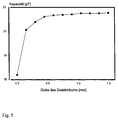
- FIG. 5 A stack of The dielectric forms an increasing number of identical PE foils with increasing thickness. In this case the dielectric constant comes the slides to wear. With increasing thickness the capacity increases.
- half-width is about half Corresponds to grid spacing.
- a narrow distance between the conductors thus reduces the Effective measurement volume thickness.
- the small thickness of the measuring volume allows a high resolution of the layers if you measure at different depths.
- the areal dimensions of 5 cm x 5 cm in FIG. 1 is advantageous, because the average is determined for certain levels.
- a punctual measurement would have the disadvantage that due to the aggregate structure of the soil measured at several points in a layer should be.
- the bottom is compacted at the edge of boreholes, so that the undisturbed water content cannot be measured.
- the electrode arrangement serves this purpose in Fig. 6.
- Conductors 1 and 2 are considered as the one capacitor electrode and conductor 3 as the other capacitor electrode, then is the effective electrode gap a. This is caused by that conductors 1 and 2 have the same potential and therefore no field can build up between them. But will in case B the conductors 1 and 3 are interconnected and form the first electrode and conductor 2 forms the other electrode, then the electrode spacing b is significantly smaller.
- the two measurements thus result in different measurement volumes recorded (see above), the measurement volume in case A essential is bigger.
- the difference (A-B) comes mainly the volume to carry, which is covered by A, but not by B.
- FIG. 6 If the arrangement of FIG. 6 is implemented on a film, can be attached to a cone or cylinder jacket, so the interference from the compaction at the edge of the borehole is prevented.
- the measurements are therefore mainly made with frequencies in the MHz and GHz range performed because then the conductivity of the soil no longer plays a role (H. Fellner-Feldegg 1969).
- the isolation of the electrodes has the advantage that the Influence of conductivity is also drastically reduced and that it becomes possible to at much lower frequencies measure that are easier to use.
- the electronic components cheaper and the circuit will less prone to interference because it becomes narrower. Furthermore there are no difficulties due to running times within the ladder on.
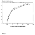
- volumetric Water content takes a form as shown in Fig. 7 is (4 series of measurements). The high initial slope of the curve shows that the arrangement is just for low values of soil water content has a high sensitivity.
- the capacitances of the capacitors 12, (see Fig. 8) with the given The electrode arrangement has a size of approximately 10 pF. It is therefore necessary to the capacitor without a long lead 13 to connect to the electronics, since cables also have a capacity between 0.3 and 3 pF / cm.
- the electronics for signal generation must also be used 3 in the ground and it is recommended to use one if possible simple arrangement to choose and for a safe signal transmission to care.
- 3 is therefore a digital signal generated, which preferably via an optical conductor 4 Evaluation electronics 6 is transmitted.
- the power supply from 3 takes place via lines 5 or via a battery in 3.
- the pulse generator 7 in FIG. 8b serves as the signal generator 3.
- the pulse length T m is accordingly determined by the capacitor 12 and the resistor 9 and the time between the pulses T d by the resistor 10 and the capacitor 11.
- T d can also transmit further information, for example the temperature, if resistor 10 is temperature-dependent is.
- the diode 8 converts the digital signal 8 into an optical signal, which can then be forwarded to the actual evaluation electronics via optical fibers without interference.
Landscapes
- Chemical & Material Sciences (AREA)
- Analytical Chemistry (AREA)
- General Health & Medical Sciences (AREA)
- Physics & Mathematics (AREA)
- Health & Medical Sciences (AREA)
- Life Sciences & Earth Sciences (AREA)
- Chemical Kinetics & Catalysis (AREA)
- Biochemistry (AREA)
- Electrochemistry (AREA)
- General Physics & Mathematics (AREA)
- Immunology (AREA)
- Pathology (AREA)
- Investigating Or Analyzing Materials By The Use Of Electric Means (AREA)
- Investigating Or Analyzing Materials By The Use Of Fluid Adsorption Or Reactions (AREA)
- Measurement Of Levels Of Liquids Or Fluent Solid Materials (AREA)
Abstract
Description
Die Erfindung betrifft einen Sensor zur Wassergehaltsbestimmung
nach dem Oberbegriff des Patentanspruchs 1.The invention relates to a sensor for determining water content
according to the preamble of
Die Ermittlung des Bodenwassergehaltes mit einfachen Mitteln ist nicht nur von wissenschaftlichem, sondern auch von kommerziellem Interesse. Darüber hinaus kommt es auch bei der Lagerung und Verarbeitung von Materialien auf die Kontrolle des Wassergehaltes an.The determination of the soil water content with simple means is not just scientific, but also commercial Interest. It also comes in storage and Processing of materials to control the water content on.
Die vergleichsweise hohe Dielektrizitätskonstante für Wasser von ε=80 legt es nahe, den Wassergehalt von Böden und anderen Materialien durch die Messung der Dielektrizitätskonstante des betroffenen Materials zu bestimmen. Trockene Böden haben eine Dielektrizitätskonstante zwischen 2 und 5, die damit deutlich kleiner als die von Wasser ist.The comparatively high dielectric constant for water from ε = 80 suggests the water content of soils and other materials by measuring the dielectric constant of the affected To determine material. Dry soils have a dielectric constant between 2 and 5, which is clear is smaller than that of water.
Da sich Kapazitätsmessungen zur Bestimmung der Dielektrizitätskonstante mit hoher Genauigkeit durchführen lassen, sind die Messungen selbst ohne Schwierigkeit im Labor und mit tragbaren Geräten möglich.Since capacitance measurements are used to determine the dielectric constant are carried out with high accuracy Measurements themselves without difficulty in the laboratory and with portable ones Devices possible.
Die Probleme sind aber deshalb vorhanden, weil die Proben bei der Entnahme und bei dem Einbringen in die Meßapparatur in ihrem strukturellen Aufbau und ihrem Wassergehalt gestört werden. Bei Sonden, die auf dem Boden aufgesetzt oder in den Boden eingestochen werden, spielt die Kopplung zwischen Boden und Sonde eine große Rolle. Insbesondere Luftspalte oder ein Wasserfilm zwischen elektrode und Boden verfälschen die Messung.The problems are there because the samples are at the removal and insertion into the measuring apparatus in their structural structure and their water content are disturbed. At Probes placed on the ground or stabbed into the ground the coupling between soil and probe plays one major role. In particular air gaps or a water film between electrode and base falsify the measurement.
Eine häufig genutzte Messmöglichkeit besteht darin, die Kapazität
eines Kondensators zu bestimmen, der den feuchten Boden als
Dielektrikum einschließt (de Plater 1955). Die Kapazität, die
den Wassergehalt anzeigt, kann durch die Resonanzfrequenz bestimmt
werden. Diese Methoden wird durch den Ausdruck
![]()
![]()
Häufig werden hohe Frequenzen im Bereich zwischen 1 MHz und 5 GHz eingesetzt. Das hat den Vorteil, daß die Leitfähigkeit keine Rolle mehr spielt und damit der Wassergehalt selektiver erfasst wird (H. Fellner-Feldegg 1969, Smith & Mullins 1991)Frequent high frequencies in the range between 1 MHz and 5 GHz used. This has the advantage that the conductivity is none Role plays more and thus the water content is recorded more selectively will (H. Fellner-Feldegg 1969, Smith & Mullins 1991)
Im hohen Frequenzbereich wird im Allgemeinen nicht mehr die Kapazität direkt gemessen, sondern Laufzeiten von Impulsen im ns- und ps-Bereich entlang von elektrischen Leitern (Time-Domain) (H. Fellner-Feldegg 1969).In the high frequency range, the capacity is generally no longer measured directly, but transit times of impulses in ns and ps range along electrical conductors (time domain) (H. Fellner-Feldegg 1969).
Eine Weiterentwicklung in Form der TDR-Methode (time-domain-reflectometry) besteht darin, daß Laufzeit und Reflexion eines elektrischen Impulses in einem Leitungspaar ausgenutzt wird (Topp et al. 1982, Dasberg & Dalton 1985). Die Laufzeit und die Reflexion des Impulses werden durch das Dielektrikum beeinflußt, das das Leiterpaar umgibt. Um die räumliche Auflösung zu verbessern, werden kleinere Ausführungen der TDR-Sonde genutzt (Amato & Ritchie 1995; Kelly et al. 1995).A further development in the form of the TDR method (time domain reflectometry) is that the running time and reflection of a electrical pulse in a pair of lines is used (Topp et al. 1982, Dasberg & Dalton 1985). The term and the Reflection of the impulse are influenced by the dielectric, that surrounds the pair of conductors. To improve spatial resolution, smaller versions of the TDR probe are used (Amato & Ritchie 1995; Kelly et al. 1995).
Wenn man nun den geometrischen Aufbau der Elektroden für die Bestimmung des Wassergehalts nach der Kapazitätsmethode betrachtet, ergibt sich folgendes Bild:If you now look at the geometric structure of the electrodes for the determination the water content considered according to the capacity method, the following picture emerges:
Plattenkondensator und ringförmiger Kondensator werden für den Fall benutzt, daß Proben entnommen werden und in eine Meßkammer eingebracht werden (Wobschall 1978, Sarabandi & Li 1994). Zylindersymmetrische Anordnungen, die dem Koaxialkabel entsprechen, werden ebenfalls als Probenräume benutzt (Fellner-Feldegg 1969, Topp et al. 1982).Plate capacitor and annular capacitor are for the Case used that samples are taken and placed in a measuring chamber be introduced (Wobschall 1978, Sarabandi & Li 1994). Cylindrical symmetry Arrangements corresponding to the coaxial cable are also used as rehearsal rooms (Fellner-Feldegg 1969, Topp et al. 1982).
Für in-situ-Messungen werden Plattenkondensatoren in verschiedener Anordnung (de Plater 1955, Dean et al. 1987)) und zwei oder drei parallele Stäbe (Dasberg & Dalton 1985, Nadler & Lapid 1996) oder ringförmige bzw. zylinderförmige Anordnungen (Campbell 1990, Ould Mohamed 1997) benutzt, die in den Boden eingestochen oder aufgesetzt (Brisco et al. 1992) werden können.For in-situ measurements, plate capacitors are used in different ways Arrangement (de Plater 1955, Dean et al. 1987)) and two or three parallel bars (Dasberg & Dalton 1985, Nadler & Lapid 1996) or annular or cylindrical arrangements (Campbell 1990, Ould Mohamed 1997) used in the ground can be pierced or put on (Brisco et al. 1992).
Neben den angegebenen Methoden gibt es noch eine Reihe von anderen Methoden wie Leitfähigkeit, Neutronenstreuung oder tensiometrische Methoden, die aber keinen direkten Bezug zur kapazitiven Messung haben (Schmugge et al. 1980, Smith & Mullins 1991, Gardner et al. 1991).In addition to the specified methods, there are a number of others Methods such as conductivity, neutron scattering or tensiometric Methods that are not directly related to the capacitive Have measurement (Schmugge et al. 1980, Smith & Mullins 1991, Gardner et al. 1991).
Die räumliche Auflösung der Sonden erreicht keine Werte unter 1
cm. Die kleinste Ausführung der TDR-Sonden wird durch Amatso &
Ritchi (1995) beschrieben. Dabei ist die Länge der Sondenstäbe
21 mm und deren Abstand 14 mm, so daß für die zeitliche Auflösung
des elektrischen Impulses 100 ps und weniger notwendig
sind. Kelly et al. (1995) befassen sich speziell mit diesem Problem
und zeigen, dass auch mit einer gesteigerten Bandbreite der
Messapparatur (20 GHz) keine bessere räumliche Auflösung zu erzielen
ist. Sie belegen, dass insbesondere bei trockenen Böden
die Genauigkeit aufgrund der niedrigen Laufzeiten abnimmt. Da
diese zeitliche Auflösung nicht ohne weiteres gesteigert werden
kann, ist die räumliche Auflösung für die TDR-Methode auf etwa 1
cm beschränkt.The spatial resolution of the probes does not reach values below 1
cm. The smallest version of the TDR probes is made by Amatso &
Ritchi (1995). The length of the
Wird eine Sonde mit Koaxialgeometrie senkrecht auf den Boden aufgesetzt, dann beeinflußt der Bodenwassergehalt bis zu einer Tiefe von 1 cm das Meßsignal (Brisco et a. 1992).Becomes a probe with coaxial geometry perpendicular to the ground put on, then the soil water content affects up to one Depth of 1 cm the measurement signal (Brisco et a. 1992).
Aufgrund der räumlichen Struktur des Bodens mit Aggregatgrößen im Bereich zwischen cm und µm und entsprechenden Poren zwischen den Aggregaten, variiert die Bodenfeuchtigkeit aber auch im mm- und µm-Bereich. Außerdem ändert sich der Bodenwassergehalt beträchtlich, wenn man sich der Bodenoberfläche oder anderen Grenzflächen nähert (Behälterflächen). Wie die Arbeiten von Amatso & Ritchi (1995) und Kelly et al. (1995) darlegen, ist eine Steigerung der räumlichen Auflösung von Vorteil. Due to the spatial structure of the floor with aggregate sizes in the range between cm and µm and corresponding pores between the aggregates, the soil moisture also varies in mm and µm range. In addition, the soil water content changes considerably, if you look at the floor surface or other Interfaces approach (container surfaces). Like the work of Amatso & Ritchi (1995) and Kelly et al. (1995) is an increase in spatial resolution is an advantage.
Darüber hinaus muß berücksichtigt werden, daß allein die Größe
einer Sonde und deren Gehäuse die Bodenstruktur ändert und damit
auch die Feuchtigkeitsverteilung. Jeder Fremdkörper im Boden erzeugt
eine entsprechende
Bei der Kontrolle der Bewässerung von Pflanzen spielt insbesondere die Messung des niedrigen Wassergehalts eine große Rolle. Die TDR-Sonde hat aber genau in diesem Bereich ihre größten relativen Messfehler (Kelly et al. 1995).When controlling the irrigation of plants in particular plays measuring the low water content plays a major role. However, the TDR probe has its greatest relative in this area Measurement error (Kelly et al. 1995).
Schrumpfen und Schwellen des Bodens während der Trocknung und Wiederbefeuchtung führen zu Rissen. Da feste Fremdkörper diese Prozesse nicht mitmachen, treten diese Risse bevorzugt an deren Oberfläche auf. Das wiederum führt zu einem Luftspalt und bei Wiederbefeuchten zu einem Wasserfilm. Beides verfälscht die Messungen (Smith & Mullins 1991).Shrinking and swelling of the soil during drying and Remoistening leads to cracks. Because solid foreign objects this Processes do not participate, these cracks prefer to appear on their Surface on. This in turn leads to an air gap and Remoisten to a water film. Both falsify the measurements (Smith & Mullins 1991).
Im Allgemeinen wird die Resonanzfrequenz bestimmt und daraus der relative volumetrische Wassergehalt aufgrund einer Kalibrierung errechnet. Bei der TDR-Methode kann aus der Phasenverschiebung noch eine Zusatzinformation über die Leitfähigkeit erhalten werden (Campbell 1990, Smith & Mullins 1991). Weitere Zusatzinformation, z.B. über die Aggregatgröße wäre von Vorteil. In general, the resonance frequency is determined and from that the relative volumetric water content due to calibration calculated. With the TDR method, the phase shift additional information about the conductivity can be obtained (Campbell 1990, Smith & Mullins 1991). Further additional information, e.g. about the aggregate size would be an advantage.
Der Wassergehalt im Boden ändert sich laufend, auch in Abhängigkeit von der Tiefe. Deshalb sind kontinuierliche Messungen vorteilhaft. Darüber hinaus sollte die Sonde auch über mehrere Monate stabil sein, weil auch Langzeitmessungen notwendig sind und weil der Boden einige Zeit braucht, bis er nach Einbringen der Sonde seine natürliche Struktur erreicht (Nadler & Lapid 1996). Die Sonde sollte also nicht zu häufig gewechselt werden müssen.The water content in the soil changes continuously, also depending on it from the depth. That is why continuous measurements are advantageous. In addition, the probe should also last for several months be stable because long-term measurements are also necessary and because it takes some time for the floor to fill up with the Probe reaches its natural structure (Nadler & Lapid 1996). So the probe should not have to be changed too often.
Da für die Erfassung der räumlichen Variabilität eine gewisse Anzahl von Sonden notwendig ist, spielt der Preis eine Rolle.As a certain for the detection of spatial variability Number of probes is necessary, price plays a role.
Aufgabe der Erfindung ist es, einen Sensor der e. g. Art so auszugestalten, daß er bei einfachem Aufbau eine hohe Ortsauflösung besitzt.The object of the invention is a sensor of the e. G. Way of designing that it has a high spatial resolution with a simple structure owns.
Gelöst wird diese Aufgabe durch die Merkmale des Patentanspruchs
1, die Unteransprüche beschreiben vorteilhafte Ausgestaltungen
der Erfindung.This object is achieved by the features of the
Die Erfindung wird im folgenden anhand von Ausführungsbeispielen mit Hilfe der Figuren näher erläutert.The invention is described below using exemplary embodiments explained in more detail with the help of the figures.
Dabei zeigen die Fig. 1, 2, 3 und 7 verschiedene Ausbildungen des Sensors.1, 2, 3 and 7 show different designs of the sensor.
Die Fig. 4, 5 und 7 zeigen die Abhängigkeit der Kapazität als Funktion von Abstand und Verteilung des Dielektrikums und vom Abstand der Kondensatorelektroden.4, 5 and 7 show the dependence of the capacity as Function of distance and distribution of the dielectric and of Distance of the capacitor electrodes.
In Fig. 1 ist eine weitgehend den Wasserstrom nicht störende
Kondensatorausführung abgebildet. Zwei Drähte 1 bilden die Kondensatorelektroden.
Sie sind in einem Rahmen 2 so gespannt, dass
sie ein Gitter bilden und durch ihre Überkreuzung jeder
Drahtabschnitt der einen Elektrode zwischen zwei Drahtabschnitten
der anderen Elektrode liegt. Dabei deutet die durchgezogene
Linie von 1 einen Verlauf oberhalb des Rahmens 2 an und die gepunktete
Line einen Verlauf unterhalb von 2. Der Minimal- und
Maximalabstand der Drähte 1 ist 0,1 mm beziehungsweise 5 mm. für
den Einsatz im Boden ist ein Abstand von 2,5 mm optimal. Die
Rahmenöffnung hat eine Größe zwischen 1 cm2 und 25 cm2 und es
sollten zwischen 5 und 20 Drahtpaare vorhanden sein.1 shows a condenser design which does not largely disturb the water flow. Two
Der Rahmen wird waagrecht in den Boden eingebracht. Da insbesondere der Wassergehalt zwischen den Drähten die Kapazität beeinflußt, ist das effektive Messvolumen flächenförmig und liegt in der Rahmenöffnung. Wenn der Drahtdurchmesser kleiner oder höchstens gleich doppelten Drahtabstand ist, wird der Wasserfluß durch das Messvolumen nur geringfügig beeinträchtigt. Ebenso kann das verdunstete Wasser ohne Behinderung nach oben entweichen. Der Raum um den Rahmen dagegen, bei dem der Wasserfluß gestört ist, trägt nich zur Messung bei weil kein Wasser in das Rahmenmaterial eindringt und das Wasser in diesem Bereich durch Verklebung mit zusätzlichem Material nicht in die Nähe des Drahtes kommt.The frame is placed horizontally in the floor. Because in particular the water content between the wires affects the capacity, the effective measurement volume is flat and lies in the frame opening. If the wire diameter is smaller or at most is equal to twice the wire spacing, the water flow only slightly affected by the measurement volume. As well the evaporated water can escape upwards without hindrance. The space around the frame, on the other hand, where the water flow is disturbed does not contribute to the measurement because there is no water in it Frame material penetrates and the water in this area through Do not glue additional material near the wire is coming.
Die Kapazität dieser Elektrodenanordnung hängt von der Drahtlänge und besonders vom Drahtabstand ab. Damit wird die Messgenauigkeit durch die Stabilität des Drahtabstandes bestimmt. Um diese Stabilität zu erhöhen, sind die Drähte mit einer bestimmten mechanischen Spannung an dem Rahmen befestigt. Die Spannung muß so groß sein, daß die Drähte durch die Inhomogenitäten im Boden (Aggregate verschiedener Größe, Steine) nicht aus ihrer Position verschoben werden.The capacity of this electrode arrangement depends on the wire length and especially on the wire spacing. This is the measurement accuracy determined by the stability of the wire spacing. Around to increase this stability are the wires with a certain mechanical tension attached to the frame. The voltage must be so large that the wires are inhomogeneous in the Soil (aggregates of various sizes, stones) not from theirs Position to be moved.
Bei Schrumpfung und Schwellung des Bodens während der Trocknung und der Wiederbefeuchtung sollen aber die Drähte eine Lagekorrektur mitmachen. Es bilden sich dann in dem betrachteten Meßvolumen keine Spalten und Risse, wie es bei festen Körpern passiert. Dadurch werden die Verfälschungen durch Luftspalte und Wasserfilme vermieden. Die mechanische Spannung darf daher nicht zu groß sein, damit die Drähte der Lagekorrektur folgen können. If the floor shrinks and swells during drying and rewetting the wires should correct the position participate. It then forms in the volume under consideration no gaps and cracks, as happens with solid bodies. This eliminates the adulteration caused by air gaps and Avoided water films. The mechanical tension is therefore not allowed be too large for the wires to follow the position correction.
Durch beide Anforderungen an die Stabilität der Drähte läßt sich die mechanische Spannung quantifizieren. Ein einzelner kleiner Stein von 10 g darf nur zu einer Auslenkung von weniger als 0.1 mm führen (laterale Spannung mindestens 1 N/mm). Andererseits muß eine Kraft von z.B. 10 N, die dem Gewicht des Bodens über dem Drahtgitter entspricht, zu einer Auslenkung von 2 mm führen. Diese Auslenkung entspricht einem großen Riß im Boden bei Schrumpfung (laterale Spannung höchstens 5 N/mm). Bei einem steinigen, sehr inhomogenen Boden muß die mechanische Spannung größer sein, so daß ein Bereich von 1 N/mm bis 20 N/mm sinnvoll erscheint.Both requirements for the stability of the wires can be met quantify the mechanical stress. A single little one 10 g stone may only be deflected by less than 0.1 mm (lateral tension at least 1 N / mm). On the other hand a force of e.g. 10 N, which is about the weight of the soil corresponds to the wire mesh, lead to a deflection of 2 mm. This deflection corresponds to a large crack in the floor Shrinkage (lateral tension at most 5 N / mm). At a stony, very inhomogeneous soil, the mechanical tension be larger, so that a range from 1 N / mm to 20 N / mm makes sense appears.
Die Spannung der Drähte kann z.B. dadurch hervorgerufen werden, daß der Rahmen während der Befestigung der Drähte in einem Schraubstock so gebogen wird, daß die entsprechende Länge um 5 % gekürzt wird (siehe Fig. 1). Nach Ende der Drahtbefestigung wird der Rahmen entspannt, so daß dadurch die Drähte selbst gespannt werden.The tension of the wires can e.g. caused by that the frame during the attachment of the wires in one Vise is bent so that the corresponding length by 5% is shortened (see Fig. 1). After the wire fastening is finished the frame relaxes, so that the wires themselves are tensioned become.
Die Anordnung von Fig. 1 ist auch deshalb von Vorteil, weil kleine Positionsänderungen eines Drahtes keinen Einfluß auf die Kapazität haben. Wird z.B. durch eine Inhomogenität im Boden ein Draht innerhalb der Ebene verschoben, dann nähert er sich dem benachbarten Draht der anderen Elektrode, so dass die Kapazität in diesem Bereich vergrößert wird. Gleichzeitig rückt er von dem anderen Drahtabschnitt derselben Elektrode ab, so dass in diesem Bereich die Kapazität erniedrigt wird. Obwohl die Abstandsabhängigkeit der Kapazität nicht linear ist, erfolgt ein gewisser Ausgleich.The arrangement of Fig. 1 is also advantageous because small changes in position of a wire have no influence on the Have capacity. E.g. due to an inhomogeneity in the soil Wire moved within the plane, then it approaches that neighboring wire of the other electrode so that the capacity is enlarged in this area. At the same time, he moves away from that other wire section of the same electrode so that in this Area the capacity is lowered. Although the distance dependency the capacity is not linear, there is some Compensation.
Der Rahmen kann in geeigneter Weise durch eine gelochte Epoxy-Platine realisiert werden, da das Material eine angemessene Biegefestigkeit hat und außerdem mit Löchern für die Drähte in präzisem Abstand versehen ist.The frame can be suitably through a perforated epoxy board be realized because the material has adequate flexural strength has and moreover with holes for the wires in precise Distance is provided.
Die Elektroden des Gitters können auch durch elasitsche Blattfedern realisiert werden. Sie sind im Ramen so angebracht, daß ihre Breitseite senkrecht steht und damit den Wasserbewegung nach oben und unten nicht behindert. Der Vorteil liegt darin, daß die Kondensatorfläche wesentlich vergrößert wird und die Messungen genauer und weniger störanfällig sind. Allerdings sollte die Blattfederbreite nicht größer sein als das fünffache des Abstandes.The electrodes of the grid can also be made by elastic leaf springs will be realized. They are so attached in the frame that its broad side is vertical and thus the water movement not hindered up and down. The advantage is that the capacitor area is significantly increased and the Measurements are more accurate and less prone to interference. Indeed the leaf spring width should not be greater than five times of distance.
Die Kondensatorelektroden können auch in Form von zwei parallelen Drähten realisiert werden, die um einen Zylinder (siehe Fig. 2) oder Kegel gewickelt sind oder die kammförmig auf dem Zylindermantel befestigt sind. Bei passendem Durchmesser können sie in Böhrlöcher eingeführt werden und den Wassergehalt in der Umgebung des Bohrlochs messen. Der Kegel hat den Vorteil, daß der Kontakt zwischen Elektroden und Boden verbessert ist.The capacitor electrodes can also be in the form of two in parallel Wires can be realized that around a cylinder (see Fig. 2) or cones are wrapped or comb-shaped on the cylinder jacket are attached. With a suitable diameter, they can be introduced into boreholes and the water content in the area of the borehole. The cone has the advantage that the Contact between electrodes and floor is improved.
Weitere Ausführungen können als Leiterbahnen auf Folien erstellt werden, die dann z. B. um Zyliner- und Kegelmäntel gewickelt werden.Other versions can be created as conductor tracks on foils be then z. B. wrapped around cylinder and cone shells become.
Die Elektroden des Kondensators können auch durch Leiterbahnen auf zweiseitig bedruckten Platinen realisiert werden. Neben der Anordnungen in Fig. 1 kann auch eine kammförmige Anordnung gewählt werden (Fig. 3). Die Leiterbahnen haben den Vorteil, dass die Leiter einen stabilen Abstand haben und dass dieser Abstand im Vergleich zu den Drähten im Rahmen auf z.B. 0.4 mm reduziert wird. Damit werden die Abmessungen der ganzen Sonde reduziert. Ein Nachteil besteht darin, dass die Platinenfläche fest ist und die oben angegebenen Störungen auftreten können. Aufgrund der kleinen Abmessungen wird das aber weitgehend bedeutungslos, wenn man die Platinen senkrecht in den Boden einbringt.The electrodes of the capacitor can also be connected by conductor tracks can be realized on double-sided printed circuit boards. In addition to the Arrangements in Fig. 1 can also be a comb-shaped arrangement be (Fig. 3). The conductor tracks have the advantage that the conductors have a stable distance and that this distance compared to the wires in the frame on e.g. 0.4 mm reduced becomes. This reduces the dimensions of the entire probe. A disadvantage is that the board surface is solid and the above-mentioned faults can occur. Due to the small dimensions, this is largely meaningless if the boards are inserted vertically into the floor.
Eine weitere Miniaturisierung läßt sich erreichen, wenn die Elektroden des Kondensators sowie die folgende elektronische Schaltung in Form eines integrierten Schaltkreises realisiert werden. A further miniaturization can be achieved if the Electrodes of the capacitor as well as the following electronic Circuit implemented in the form of an integrated circuit become.
Der Abstand der Elektroden in Fig. 1 und 2 bestimmt die
Auch bei der Platine mit einem Leiterbahnabstand von 0,4 mm wird das empfindliche Volumen getestet (Fig. 5). Ein Stapel mit steigender Zahl von identischen PE-Folien bildet das Dielektrikum mit zunehmender Dicke. In diesem Fall kommt die Dielektrizitätskonstante der Folien zum Tragen. Mit zunehmender Dicke steigt die Kapazität an.Also for the circuit board with a track spacing of 0.4 mm the sensitive volume is tested (Fig. 5). A stack of The dielectric forms an increasing number of identical PE foils with increasing thickness. In this case the dielectric constant comes the slides to wear. With increasing thickness the capacity increases.
Auch hier erkennt man, dass die Halbwertsbreite etwa dem halben Gitterabstand entspricht.Here you can also see that the half-width is about half Corresponds to grid spacing.
Ein enger Abstand zwischen den Leitern verringert damit die Dicke des effektiven Messvolumens.A narrow distance between the conductors thus reduces the Effective measurement volume thickness.
Die geringe Dicke des Messvolumens erlaubt eine hohe Auflösung der Schichten, wenn man in verschiedener Bodentiefe misst. Die flächenhafte Ausmaße von 5 cm x 5 cm in Fig. 1 ist vorteilhaft, weil der Mittelwert für bestimmte Ebenen ermittelt wird. Eine punktuelle Messung hätte den Nachteil, dass aufgrund der Aggregatstruktur des Bodens an mehreren Stellen einer Schicht gemessen werden müßte.The small thickness of the measuring volume allows a high resolution of the layers if you measure at different depths. The areal dimensions of 5 cm x 5 cm in FIG. 1 is advantageous, because the average is determined for certain levels. A punctual measurement would have the disadvantage that due to the aggregate structure of the soil measured at several points in a layer should be.
Wie schon oben angesprochen, können Fehlmessungen auftreten, wenn sich an der Elektrodenoberfläche ein Luftspalt bildet, der dann bei Wiederbefeuchten auch Raum für einen Wasserfilm bietet. As mentioned above, incorrect measurements can occur if an air gap forms on the electrode surface that then also offers space for a film of water when rewetting.
Darüber hinaus ist der Boden am Rand von Bohrlöchern verdichtet, so daß nicht der ungestörte Wassergehalt gemessen werden kann.In addition, the bottom is compacted at the edge of boreholes, so that the undisturbed water content cannot be measured.
Es ist deshalb von Vorteil, den Wassergehalt in einem bestimmten
Abstand von der Detektorfläche zu messen. Dazu dient die Elektrodenanordnung
in Fig. 6. Werden im Fall A die zusammengeschalteten
Leiter 1 und 2 als die eine Kondensatorelektrode betrachtet
und der Leiter 3 als die andere Kondensatorelektrode, dann
ist der effektive Elektrodenabstand a. Das wird dadurch hervorgerufen,
daß die Leiter 1 und 2 dasselbe Potential haben und
sich deshalb kein Feld zwischen ihnen aufbauen kann. Werden aber
im Fall B die Leiter 1 und 3 zusammengeschaltet und bilden die
erste Elektrode und Leiter 2 bildet die andere Elektrode, dann
ist der Elektrodenabstand b wesentlich kleiner.It is therefore advantageous to have a specific water content
Measure distance from the detector surface. The electrode arrangement serves this purpose
in Fig. 6. Are the interconnected in
Damit werden durch die beiden Messungen verschiedene Meßvolumina erfaßt (siehe oben), wobei das Meßvolumen im Fall A wesentlich größer ist. Bei der Differenzbildung (A-B) kommt hauptsächlich das Volumen zum Tragen, das durch A erfaßt wird, nicht aber durch B.The two measurements thus result in different measurement volumes recorded (see above), the measurement volume in case A essential is bigger. The difference (A-B) comes mainly the volume to carry, which is covered by A, but not by B.
Wenn die Anordnung von Fig. 6 auf einer Folie realisiert ist, kann sie auf einem Kegel- oder Zylindermantel befestigt werden, so daß die Störungen durch die Verdichtung am Rand des Bohrlochs verhindert wird.If the arrangement of FIG. 6 is implemented on a film, can be attached to a cone or cylinder jacket, so the interference from the compaction at the edge of the borehole is prevented.
Die Abhängigkeit der (komplexen) Dielektrizitätskonstante von der Leitfähigkeit σ ist bekannt und zeigt im Idealfall ein Absinken des imaginären Anteils proportional zu 1/σ.The dependence of the (complex) dielectric constant on the conductivity σ is known and ideally shows a decrease of the imaginary part proportional to 1 / σ.
Die Messungen werden hauptsächlich deshalb mit Frequenzen im MHz- und GHz-Bereich durchgeführt, weil dann die Leitfähigkeit des Bodens keine Rolle mehr spielt (H. Fellner-Feldegg 1969). Die Isolation der Elektroden bringt aber den Vorteil, daß der Einfluß der Leitfähigkeit ebenfalls drastisch reduziert wird und daß es möglich wird, bei wesentlich niedrigeren Frequenzen zu messen, die einfacher zu handhaben sind. Insbesondere werden die elektronischen Komponenten preiswerter und die Schaltung wird weniger störanfällig, weil sie schmalbandiger wird. Außerdem treten keine Schwierigkeiten durch Laufzeiten innerhalb der Leiter auf.The measurements are therefore mainly made with frequencies in the MHz and GHz range performed because then the conductivity of the soil no longer plays a role (H. Fellner-Feldegg 1969). The isolation of the electrodes has the advantage that the Influence of conductivity is also drastically reduced and that it becomes possible to at much lower frequencies measure that are easier to use. In particular, the electronic components cheaper and the circuit will less prone to interference because it becomes narrower. Furthermore there are no difficulties due to running times within the ladder on.
Durch die Isolierung besteht aber kein linearer Zusammenhang zwischen Bodenwassergehalt und Dielektrizitätskonstante mehr, sondern die Abhängigkeit zwischen Kapazität und rel. volumetrischen Wassergehalt nimmt eine Form an, wie sie in Fig. 7 dargestellt ist (4 Meßreihen). Die hohe Anfangssteigung der Kurve zeigt, daß die Anordnung gerade für niedrige Werte an Bodenwassergehalt eine hohe Empfindlichkeit aufweist.Due to the isolation there is no linear relationship between soil water content and dielectric constant more, but the dependence between capacity and rel. volumetric Water content takes a form as shown in Fig. 7 is (4 series of measurements). The high initial slope of the curve shows that the arrangement is just for low values of soil water content has a high sensitivity.
Die Kapazitäten der Kondensatoren 12, (siehe Fig. 8) mit der gegebenen
Elektrodenanordnung haben eine Größe von etwa 10 pF. Es
ist deshalb notwendig, den Kondensator ohne lange Zuleitung 13
an die Elektronik anzuschließen, da Leitungen ebenfalls eine Kapazität
zwischen 0.3 und 3 pF/cm haben.The capacitances of the
Bei Sonden im Boden muß daher auch die Elektronik zur Signalerzeugung
3 in den Boden und es empfiehlt sich, eine möglichst
einfache Anordnung dafür zu wählen und für eine sichere Signalübertragung
zu sorgen. Deshalb wird in 3 ein Digitales Signal
erzeugt, das vorzugsweise über einen optischen Leiter 4 zur
Auswerteelektronik 6 übertragen wird. Die Stromversorgung von 3
erfolgt über die Leitungen 5 oder über eine Batterie in 3.In the case of probes in the ground, the electronics for signal generation must also be used
3 in the ground and it is recommended to use one if possible
simple arrangement to choose and for a safe signal transmission
to care. 3 is therefore a digital signal
generated, which preferably via an
Als Signalgenerator 3 dient im einfachsten Fall der Pulsgenerator
7 in Fig. 8b. Die Pulslänge Tm wird demnach durch den Kondensator
12 und den Widerstand 9 bestimmt und die Zeit zwischen
den Impulsen Td durch den Widerstand 10 und den Kondensator 11.
Td kann auch noch eine weitere Information übertragen, z.B. die
Temperatur, wenn Widerstand 10 temperaturabhängig ist. Das digitale
Signal 8 wird mit der Diode in ein optisches Signal umgewandelt,
das dann über Lichtleiter ohne Störungen zur eigentlichen
Auswerteelektronik weitergeleitet werden kann.In the simplest case, the
Anwendungen ergeben sich in der Wassergehaltbestimmung im Boden mit der Bewässerungsteuerung im Gewächshaus und auch auf Ackerflächen. Darüberhinaus muß bei der Lagerung auf die Feuchtigkeit geachtet werden (Heu, Getreide). Auch bei der Produktion spielt die korrekte Einstellung der Feuchtigkeit eine Rolle (Tabak). Die Ausführungen in Zylinderform oder Kegelform können als Stichsonden eingesetzt werden. Applications arise in the determination of water content in the soil with irrigation control in the greenhouse and also on arable land. In addition, moisture must be used during storage be respected (hay, grain). Also plays in the production the correct setting of moisture is a role (tobacco). The versions in cylindrical or conical shape can be used as Stab probes can be used.
Claims (8)
Applications Claiming Priority (2)
| Application Number | Priority Date | Filing Date | Title |
|---|---|---|---|
| DE19744784A DE19744784A1 (en) | 1997-10-10 | 1997-10-10 | Sensor for water content determination |
| DE19744784 | 1997-10-10 |
Publications (2)
| Publication Number | Publication Date |
|---|---|
| EP0911628A1 true EP0911628A1 (en) | 1999-04-28 |
| EP0911628B1 EP0911628B1 (en) | 2001-08-08 |
Family
ID=7845154
Family Applications (1)
| Application Number | Title | Priority Date | Filing Date |
|---|---|---|---|
| EP98117103A Expired - Lifetime EP0911628B1 (en) | 1997-10-10 | 1998-09-10 | Sensor for determining water content |
Country Status (3)
| Country | Link |
|---|---|
| EP (1) | EP0911628B1 (en) |
| AT (1) | ATE204081T1 (en) |
| DE (2) | DE19744784A1 (en) |
Cited By (2)
| Publication number | Priority date | Publication date | Assignee | Title |
|---|---|---|---|---|
| EP1607739A1 (en) * | 2004-06-18 | 2005-12-21 | Eidgenössiche Technische Hochschule Zürich | Capacitive sensor |
| US8633047B2 (en) | 2011-09-02 | 2014-01-21 | Sensirion Ag | Method for manufacturing a sensor chip |
Families Citing this family (2)
| Publication number | Priority date | Publication date | Assignee | Title |
|---|---|---|---|---|
| DE10204347A1 (en) | 2002-02-01 | 2003-08-14 | Atmel Germany Gmbh | Process for the transmission of data |
| DE102009011278B4 (en) * | 2009-03-05 | 2017-04-20 | Imko Micromodultechnik Gmbh | Probe and device for determining the moisture content or conductivity of a medium |
Citations (4)
| Publication number | Priority date | Publication date | Assignee | Title |
|---|---|---|---|---|
| US3424977A (en) * | 1966-05-04 | 1969-01-28 | Human Resources Foundation | Capacitive device responsive to water vapor content of a gas including insulated conductive wire electrodes forming a grid |
| US4502044A (en) * | 1982-05-19 | 1985-02-26 | Farris James R | Moisture alarm system |
| GB2256489A (en) * | 1991-05-31 | 1992-12-09 | Natural Environment Res | Capacitative measuring apparatus |
| EP0622628A2 (en) * | 1993-04-29 | 1994-11-02 | imko INTELLIGENTE MICROMODULE KÖHLER GmbH | Probe sensing the humidity of materials |
Family Cites Families (3)
| Publication number | Priority date | Publication date | Assignee | Title |
|---|---|---|---|---|
| CH674085A5 (en) * | 1988-03-03 | 1990-04-30 | Martin Ineichen | |
| DE3911812C2 (en) * | 1989-04-11 | 1996-09-19 | Siemens Ag | Fast polymer-based moisture sensor |
| DE4139356A1 (en) * | 1991-11-29 | 1993-06-03 | Armin Dr Brather | Plate measurement capacitor for determining electrical and dielectric parameters - has three plates, two planar outer electrodes at the same potential and intermediate counter-electrode, with stiff lead mounting and guide |
-
1997
- 1997-10-10 DE DE19744784A patent/DE19744784A1/en not_active Ceased
-
1998
- 1998-09-10 DE DE59801155T patent/DE59801155D1/en not_active Expired - Fee Related
- 1998-09-10 EP EP98117103A patent/EP0911628B1/en not_active Expired - Lifetime
- 1998-09-10 AT AT98117103T patent/ATE204081T1/en active
Patent Citations (4)
| Publication number | Priority date | Publication date | Assignee | Title |
|---|---|---|---|---|
| US3424977A (en) * | 1966-05-04 | 1969-01-28 | Human Resources Foundation | Capacitive device responsive to water vapor content of a gas including insulated conductive wire electrodes forming a grid |
| US4502044A (en) * | 1982-05-19 | 1985-02-26 | Farris James R | Moisture alarm system |
| GB2256489A (en) * | 1991-05-31 | 1992-12-09 | Natural Environment Res | Capacitative measuring apparatus |
| EP0622628A2 (en) * | 1993-04-29 | 1994-11-02 | imko INTELLIGENTE MICROMODULE KÖHLER GmbH | Probe sensing the humidity of materials |
Non-Patent Citations (3)
| Title |
|---|
| AMATO M ET AL: "Small spatial scale soil water content measurement with time-domain reflectometry", SOIL SCIENCE SOCIETY OF AMERICA JOURNAL, vol. 59, 1995, ISSN 0361-5995, pages 325 - 329, XP002091083 * |
| FROLOV G V ET AL: "A quasibalancing dielectric water-content meter for powdery building materials", MEASUREMENT TECHNIQUES, vol. 27, no. 5, May 1984 (1984-05-01), ISSN 0543-1972, pages 468 - 470, XP002091082 * |
| SHEIRETOV Y ET AL: "Dielectrometry measurements of spatial moisture profiles in oil-impregnated pressboard", PROCEEDINGS OF THE 4TH INTERNATIONAL CONFERENCE ON PROPERTIES AND APPLICATIONS OF DIELECTRIC MATERIALS (IEEE CAT. NO.94CH3311-8), vol. 2, 1994, ISBN 0-7803-1307-0, pages 701 - 704, XP000749804 * |
Cited By (4)
| Publication number | Priority date | Publication date | Assignee | Title |
|---|---|---|---|---|
| EP1607739A1 (en) * | 2004-06-18 | 2005-12-21 | Eidgenössiche Technische Hochschule Zürich | Capacitive sensor |
| EP2278310A1 (en) * | 2004-06-18 | 2011-01-26 | Sensirion Holding AG | Capacitive sensor |
| US8633047B2 (en) | 2011-09-02 | 2014-01-21 | Sensirion Ag | Method for manufacturing a sensor chip |
| US9140740B2 (en) | 2011-09-02 | 2015-09-22 | Sensirion Ag | Sensor chip and method for manufacturing a sensor chip |
Also Published As
| Publication number | Publication date |
|---|---|
| DE19744784A1 (en) | 1999-05-06 |
| DE59801155D1 (en) | 2001-09-13 |
| EP0911628B1 (en) | 2001-08-08 |
| ATE204081T1 (en) | 2001-08-15 |
Similar Documents
| Publication | Publication Date | Title |
|---|---|---|
| EP0995083B1 (en) | Capacitative level detector with optimized electrode geometry | |
| EP2400275B1 (en) | Contactless fill level measurement of liquids | |
| DE102006019178B4 (en) | Arrangement for the two-dimensional measurement of different components in the cross-section of a multiphase flow | |
| DE19629745C2 (en) | Device and method for determining soil properties | |
| DE69203727T2 (en) | Method for dynamic contactless measurement of a displacement or dielectric constant with the help of a capacitive sensor. | |
| EP0926475A2 (en) | Capacitive level sensor with integrated impurities film detection | |
| EP0145861B1 (en) | Device for measuring pressures and temporal marches of pressure | |
| DE10256064B4 (en) | Method and device for determining the water content and conductivity in soils and bulk materials | |
| DE19713267A1 (en) | Method for determining the dielectric constant and / or the conductivity of at least one medium and device for carrying out the method | |
| DE69837878T2 (en) | APPARATUS FOR CAPACITIVE ELECTRICAL DETECTION | |
| EP3821211A1 (en) | Devices and methods for capacitively detecting foam in liquid containers | |
| EP3421950B1 (en) | Flow sensor, method and flow meter for determining velocities of phases of a multi-phase medium | |
| DD271380A5 (en) | Reflectometric moisture meter for capillary porous bodies, especially for the floor | |
| DE112006001212B4 (en) | Method and measuring device for measuring water content | |
| DE10261138B4 (en) | Soil sensor and method for measuring soil parameters | |
| EP0911628B1 (en) | Sensor for determining water content | |
| EP0760467A1 (en) | Method of determining the phase proportion of a medium in open and closed channels | |
| EP0351700B1 (en) | Arrangement for the capacitive fluid level measurement | |
| EP0621466A1 (en) | System for capacitive level measurement and its use | |
| DE4105445C2 (en) | Method and arrangement for measuring meteorological quantities using a radio probe | |
| EP0927877B1 (en) | A measuring device for a fuel gauge | |
| EP0389916B1 (en) | Apparatus for measuring the dielectric properties of materials | |
| DE1673046A1 (en) | Device for measuring soil moisture | |
| DE3402708C2 (en) | ||
| DE102018124501B3 (en) | Sensor for measuring flow profiles in large columns and apparatus |
Legal Events
| Date | Code | Title | Description |
|---|---|---|---|
| PUAI | Public reference made under article 153(3) epc to a published international application that has entered the european phase |
Free format text: ORIGINAL CODE: 0009012 |
|
| AK | Designated contracting states |
Kind code of ref document: A1 Designated state(s): AT BE CH DE DK FI FR GB IE IT LI NL SE |
|
| AX | Request for extension of the european patent |
Free format text: AL;LT;LV;MK;RO;SI |
|
| 17P | Request for examination filed |
Effective date: 19990617 |
|
| 17Q | First examination report despatched |
Effective date: 19991027 |
|
| AKX | Designation fees paid |
Free format text: AT BE CH DE DK FI FR GB IE IT LI |
|
| RBV | Designated contracting states (corrected) |
Designated state(s): AT BE CH DE DK FI FR GB IE IT LI NL SE |
|
| GRAG | Despatch of communication of intention to grant |
Free format text: ORIGINAL CODE: EPIDOS AGRA |
|
| GRAG | Despatch of communication of intention to grant |
Free format text: ORIGINAL CODE: EPIDOS AGRA |
|
| GRAH | Despatch of communication of intention to grant a patent |
Free format text: ORIGINAL CODE: EPIDOS IGRA |
|
| ITF | It: translation for a ep patent filed | ||
| GRAH | Despatch of communication of intention to grant a patent |
Free format text: ORIGINAL CODE: EPIDOS IGRA |
|
| GRAA | (expected) grant |
Free format text: ORIGINAL CODE: 0009210 |
|
| AK | Designated contracting states |
Kind code of ref document: B1 Designated state(s): AT BE CH DE DK FI FR GB IE IT LI NL SE |
|
| PG25 | Lapsed in a contracting state [announced via postgrant information from national office to epo] |
Ref country code: IE Free format text: LAPSE BECAUSE OF FAILURE TO SUBMIT A TRANSLATION OF THE DESCRIPTION OR TO PAY THE FEE WITHIN THE PRESCRIBED TIME-LIMIT Effective date: 20010808 Ref country code: FI Free format text: LAPSE BECAUSE OF FAILURE TO SUBMIT A TRANSLATION OF THE DESCRIPTION OR TO PAY THE FEE WITHIN THE PRESCRIBED TIME-LIMIT Effective date: 20010808 |
|
| REF | Corresponds to: |
Ref document number: 204081 Country of ref document: AT Date of ref document: 20010815 Kind code of ref document: T |
|
| REG | Reference to a national code |
Ref country code: CH Ref legal event code: EP |
|
| REG | Reference to a national code |
Ref country code: CH Ref legal event code: NV Representative=s name: ROTTMANN, ZIMMERMANN + PARTNER AG |
|
| REG | Reference to a national code |
Ref country code: IE Ref legal event code: FG4D Free format text: GERMAN |
|
| PG25 | Lapsed in a contracting state [announced via postgrant information from national office to epo] |
Ref country code: AT Free format text: LAPSE BECAUSE OF NON-PAYMENT OF DUE FEES Effective date: 20010910 |
|
| REF | Corresponds to: |
Ref document number: 59801155 Country of ref document: DE Date of ref document: 20010913 |
|
| PG25 | Lapsed in a contracting state [announced via postgrant information from national office to epo] |
Ref country code: BE Free format text: LAPSE BECAUSE OF NON-PAYMENT OF DUE FEES Effective date: 20010930 |
|
| PG25 | Lapsed in a contracting state [announced via postgrant information from national office to epo] |
Ref country code: SE Free format text: LAPSE BECAUSE OF FAILURE TO SUBMIT A TRANSLATION OF THE DESCRIPTION OR TO PAY THE FEE WITHIN THE PRESCRIBED TIME-LIMIT Effective date: 20011108 Ref country code: DK Free format text: LAPSE BECAUSE OF FAILURE TO SUBMIT A TRANSLATION OF THE DESCRIPTION OR TO PAY THE FEE WITHIN THE PRESCRIBED TIME-LIMIT Effective date: 20011108 |
|
| GBT | Gb: translation of ep patent filed (gb section 77(6)(a)/1977) |
Effective date: 20011106 |
|
| ET | Fr: translation filed | ||
| REG | Reference to a national code |
Ref country code: GB Ref legal event code: IF02 |
|
| BERE | Be: lapsed |
Owner name: GSF-FORSCHUNGSZENTRUM FUR UMWELT UND GESUNDHEIT G Effective date: 20010930 |
|
| PLBE | No opposition filed within time limit |
Free format text: ORIGINAL CODE: 0009261 |
|
| STAA | Information on the status of an ep patent application or granted ep patent |
Free format text: STATUS: NO OPPOSITION FILED WITHIN TIME LIMIT |
|
| 26N | No opposition filed | ||
| PGFP | Annual fee paid to national office [announced via postgrant information from national office to epo] |
Ref country code: CH Payment date: 20080828 Year of fee payment: 11 |
|
| PGFP | Annual fee paid to national office [announced via postgrant information from national office to epo] |
Ref country code: NL Payment date: 20080929 Year of fee payment: 11 Ref country code: IT Payment date: 20080827 Year of fee payment: 11 |
|
| PGFP | Annual fee paid to national office [announced via postgrant information from national office to epo] |
Ref country code: GB Payment date: 20080829 Year of fee payment: 11 |
|
| PGFP | Annual fee paid to national office [announced via postgrant information from national office to epo] |
Ref country code: DE Payment date: 20080820 Year of fee payment: 11 |
|
| PGFP | Annual fee paid to national office [announced via postgrant information from national office to epo] |
Ref country code: FR Payment date: 20080929 Year of fee payment: 11 |
|
| REG | Reference to a national code |
Ref country code: NL Ref legal event code: V1 Effective date: 20100401 |
|
| REG | Reference to a national code |
Ref country code: CH Ref legal event code: PL |
|
| GBPC | Gb: european patent ceased through non-payment of renewal fee |
Effective date: 20090910 |
|
| REG | Reference to a national code |
Ref country code: FR Ref legal event code: ST Effective date: 20100531 |
|
| PG25 | Lapsed in a contracting state [announced via postgrant information from national office to epo] |
Ref country code: NL Free format text: LAPSE BECAUSE OF NON-PAYMENT OF DUE FEES Effective date: 20100401 Ref country code: FR Free format text: LAPSE BECAUSE OF NON-PAYMENT OF DUE FEES Effective date: 20090930 Ref country code: DE Free format text: LAPSE BECAUSE OF NON-PAYMENT OF DUE FEES Effective date: 20100401 |
|
| PG25 | Lapsed in a contracting state [announced via postgrant information from national office to epo] |
Ref country code: LI Free format text: LAPSE BECAUSE OF NON-PAYMENT OF DUE FEES Effective date: 20090930 Ref country code: CH Free format text: LAPSE BECAUSE OF NON-PAYMENT OF DUE FEES Effective date: 20090930 |
|
| PG25 | Lapsed in a contracting state [announced via postgrant information from national office to epo] |
Ref country code: GB Free format text: LAPSE BECAUSE OF NON-PAYMENT OF DUE FEES Effective date: 20090910 |
|
| PG25 | Lapsed in a contracting state [announced via postgrant information from national office to epo] |
Ref country code: IT Free format text: LAPSE BECAUSE OF NON-PAYMENT OF DUE FEES Effective date: 20090910 |